EP1493874A1 - Toilettenschüssel - Google Patents
Toilettenschüssel Download PDFInfo
- Publication number
- EP1493874A1 EP1493874A1 EP04015717A EP04015717A EP1493874A1 EP 1493874 A1 EP1493874 A1 EP 1493874A1 EP 04015717 A EP04015717 A EP 04015717A EP 04015717 A EP04015717 A EP 04015717A EP 1493874 A1 EP1493874 A1 EP 1493874A1
- Authority
- EP
- European Patent Office
- Prior art keywords
- toilet bowl
- valve
- membrane
- waste water
- chamber
- Prior art date
- Legal status (The legal status is an assumption and is not a legal conclusion. Google has not performed a legal analysis and makes no representation as to the accuracy of the status listed.)
- Granted
Links
- 239000007788 liquid Substances 0.000 claims description 17
- 238000011010 flushing procedure Methods 0.000 claims description 11
- 238000009434 installation Methods 0.000 claims description 3
- 235000001674 Agaricus brunnescens Nutrition 0.000 claims 1
- 239000002351 wastewater Substances 0.000 abstract description 8
- 239000012528 membrane Substances 0.000 abstract 9
- 238000009423 ventilation Methods 0.000 abstract 3
- 230000005484 gravity Effects 0.000 abstract 1
- XLYOFNOQVPJJNP-UHFFFAOYSA-N water Substances O XLYOFNOQVPJJNP-UHFFFAOYSA-N 0.000 description 6
- 238000004140 cleaning Methods 0.000 description 5
- 239000012530 fluid Substances 0.000 description 3
- 239000007921 spray Substances 0.000 description 3
- 239000013013 elastic material Substances 0.000 description 2
- 230000002093 peripheral effect Effects 0.000 description 2
- 239000007787 solid Substances 0.000 description 2
- 241000233866 Fungi Species 0.000 description 1
- 230000015572 biosynthetic process Effects 0.000 description 1
- 238000005553 drilling Methods 0.000 description 1
- 239000003651 drinking water Substances 0.000 description 1
- 235000020188 drinking water Nutrition 0.000 description 1
- 230000007257 malfunction Effects 0.000 description 1
- 238000000034 method Methods 0.000 description 1
- 238000010926 purge Methods 0.000 description 1
- 230000000630 rising effect Effects 0.000 description 1
- 238000005507 spraying Methods 0.000 description 1
Images


Classifications
-
- E—FIXED CONSTRUCTIONS
- E03—WATER SUPPLY; SEWERAGE
- E03F—SEWERS; CESSPOOLS
- E03F1/00—Methods, systems, or installations for draining-off sewage or storm water
- E03F1/006—Pneumatic sewage disposal systems; accessories specially adapted therefore
-
- E—FIXED CONSTRUCTIONS
- E03—WATER SUPPLY; SEWERAGE
- E03D—WATER-CLOSETS OR URINALS WITH FLUSHING DEVICES; FLUSHING VALVES THEREFOR
- E03D11/00—Other component parts of water-closets, e.g. noise-reducing means in the flushing system, flushing pipes mounted in the bowl, seals for the bowl outlet, devices preventing overflow of the bowl contents; devices forming a water seal in the bowl after flushing, devices eliminating obstructions in the bowl outlet or preventing backflow of water and excrements from the waterpipe
- E03D11/02—Water-closet bowls ; Bowls with a double odour seal optionally with provisions for a good siphonic action; siphons as part of the bowl
- E03D11/10—Bowls with closure elements provided between bottom or outlet and the outlet pipe; Bowls with pivotally supported inserts
-
- E—FIXED CONSTRUCTIONS
- E03—WATER SUPPLY; SEWERAGE
- E03D—WATER-CLOSETS OR URINALS WITH FLUSHING DEVICES; FLUSHING VALVES THEREFOR
- E03D11/00—Other component parts of water-closets, e.g. noise-reducing means in the flushing system, flushing pipes mounted in the bowl, seals for the bowl outlet, devices preventing overflow of the bowl contents; devices forming a water seal in the bowl after flushing, devices eliminating obstructions in the bowl outlet or preventing backflow of water and excrements from the waterpipe
- E03D11/13—Parts or details of bowls; Special adaptations of pipe joints or couplings for use with bowls, e.g. provisions in bowl construction preventing backflow of waste-water from the bowl in the flushing pipe or cistern, provisions for a secondary flushing, for noise-reducing
Definitions
- the invention relates to a toilet bowl, in particular intended for a vacuum toilet installation, arranged in the upper edge of the toilet bowl flushing nozzle for Dispensing from the toilet bowl inside spraying liquid, the rinsing nozzle being a disc-shaped one along the toilet bowl inner surface extending first portion with an exit slot arcuate course and a in a recording of the toilet bowl extending or fixed a channel comprising the second section, via which the liquid to the outlet slot flows.
- DE-U-297 00 985 discloses a vacuum toilet. It goes from the bottom Bowl area a pipeline out, outside the bowl at a certain height ends open below the flushing nozzles. This creates an overflow that ensures that if the toilet bowl was to run through a malfunction, the water level can not get to the nozzles, causing them in an inadmissible way wastewater could suck into the drinking water line. Disadvantage of the known training is that if the suction opening of the toilet bowl is filled with paper and solids The bowl can not be properly emptied because of the outside of the bowl Toilet bowl running line false air would be sucked, so that as a result the toilet bowl can not be built up the required vacuum to the Bowl completely empty to suck.
- a plurality of nozzles are further arranged to the Rinse toilet bowl.
- the disadvantage is that part of the middle range itself can not be rinsed between two successive nozzles.
- From DE-A-25 29 169 is a device for distributing rinse water in one Toilet bowl known, consisting of a running in the upper toilet bowl edge against the Inner wall of the toilet bowl directed longitudinal channel has. There is the Device made of elastic material such as plastic or rubber.
- a toilet bowl is known that in the back area having a rinsing nozzle.
- This includes a flushing liquid leading pipe, the end is closed by a cover that enters an exit slot and side openings goes over to spray rinsing liquid in different directions.
- the slot extends in this case preferably over an angular range between 80 and 100 °.
- Two or three rinsing nozzles are in the upper edge area of a toilet bowl after the US-A-4,075,718.
- the nozzles have two approximately at an angle of 180 ° descriptive Opening slits on the liquid in different directions on the Inner surface of the toilet bowl is discharged.
- a water closet according to DE-U-86 19 586 has several extending in the upper edge region Outlet openings on the rinsing fluid in different amounts is delivered.
- the present invention is based on the problem, a toilet bowl of the beginning mentioned type, in particular intended for a vacuum toilet system, so educate that with a few nozzles ensures that the toilet bowl can be cleaned thoroughly, so that consequently only small areas remain, the can not be washed over.
- the problem is essentially solved by the Exit slot of the flushing nozzle in its respective end region merges into a bore, whose diameter D is greater than the exit slot in its width S is that the holes include an angle ⁇ with 140 ° ⁇ ⁇ ⁇ 180 ° and that of the exit slot spanned first level inclined towards the inner surface of the toilet bowl.
- the forming the marginal boundaries of the arcuate exit slot Holes in particular include an angle ⁇ with 160 ° ⁇ ⁇ ⁇ 165 °.
- the diameter D of the bore and the width S of the exit slot are preferably 1.5 S ⁇ D ⁇ 2.5 S, preferably D in about 1.8 s.
- the holes should off-center the channel passing the second section in particular, it is provided that the holes in the channel in cut its slot facing away edge area.
- the first section of the nozzle biases with its inner surface a first plane and that of outgoing channel to a second level, wherein the first and the second Level inclined to each other.
- the of the Outlet slot spanned plane inclined towards the inner surface of the toilet bowl runs.
- the first and second planes define an angle ⁇ with 4 ° ⁇ ⁇ 8 °, preferably 6 ° ⁇ ⁇ 6.5 °.
- the formation of the geometry of a fungus having nozzles results in the Advantage that two nozzles are enough to innervate the toilet bowl in the required To spray the circumference with liquid.
- the nozzles are in particular diametrically and preferably arranged centrally in a side region of the toilet bowl.
- the same toilet bowl 10 is determined in principle and the structure shown for a toilet vacuum system.
- the toilet bowl 10 consists of a double-walled body 11 and has in its lowest point, ie in the bottom region 12, a Connection to a vacuum line 14, in which a check valve 16 is located in usual way, then a connection to the toilet bowl 10, so its interior 18, when accumulated liquid and solids are to be sucked off.
- a vacuum line 14 in which a check valve 16 is located in usual way, then a connection to the toilet bowl 10, so its interior 18, when accumulated liquid and solids are to be sucked off.
- nozzles 22, 23 are arranged to surround the inner surface 24 of FIG Toilet bowl 10 to rinse.
- an overflow 28 is provided in the back region 26 of the bowl 10, formed by a chamber or channel-shaped section or a recess 30 becomes laterally in pockets such as attachment pockets 32, 34 passes over the liquid forcibly guided into the sanitary room, in which the toilet bowl 10 is located.
- the overflow 28 has an opening 36, the upper edge 38 at a distance H below the Nozzles 22, 23 runs.
- the distance H is preferably about 20 mm.
- the channel-shaped portion 30 of the toilet bowl has one of the Opening 36 outgoing rising channel-shaped bottom 40, thereby ensuring is that when unintentionally liquid flows into the section 30, this in the Area 18 of the toilet bowl 10 can flow back. This results in a kind of self-cleaning. Furthermore, the leading to the side pockets 30, 32 openings of the Recess 30 cross-sectionally designed such that a cleaning of the channel or the chamber, d. H. the overflow 28 can be done by hand. The in the embodiment too The attachment pockets 32, 34 leading outlets extend above the gutter-shaped bottom 40.
- the toilet wall 42 in comparison to the formed below the opening 36 extending portion 44 projecting, such as in particular the view A in Fig. 3 illustrates.
- the geometry and height arrangement of the overflow 28 ensures that when the toilet bowl 10 inadmissible with Liquid should be filled, this targeted from the toilet bowl over the overflow 28 too the attachment pockets 32, 34 is guided to the bottom portion of the sanitary room in which the Toilet bowl 10 is arranged. Thus, it is ensured that the nozzles 22, 23 not with can come into contact with the wastewater.
- nozzles 22, 23 are in the upper edge region of the Toilet body 11 alone two nozzles 22, 23 provided to over this Cleaning fluid for cleaning the inner surface 24 of the toilet bowl 10, i. their To spray body 11.
- the nozzles 22, 23 are diametrically opposite and approximately in the middle arranged in each longitudinal side.
- Each nozzle 22, 23 consists of a mushroom-shaped body, which extends from one along the Inner surface 24 in the upper edge 20 of the toilet bowl 10 extending first portion 44th and a second portion 46 extending into the body 11.
- the second section 46 is penetrated by a central channel 48, via the Rinsing fluid is zuleitbar.
- From the channel 48 is an arcuate course comprising slot 50, which opens in the peripheral edge 52 of the first portion 44.
- there the exit slot 50 extends over an arc, preferably in the range of 160 ° is up to 165 ° and the bottom portion of the bowl 10 faces.
- the extension takes place while symmetrical to the vertical axis 54, which is perpendicular or approximately perpendicular to a plane runs, which is spanned by the nozzles 22, 23 and parallel to the upper edge 20 of the Toilet bowl 10 runs.
- the slot 50 passes in its respective end into a bore 56, 58, whose Diameter D is greater than the slot 50 in its width S is.
- the diameter is thereby about 1.8 times the width S of the slot 50.
- the bores 56, 58 are - as the exit slot 50 - from the channel 48, over the the cleaning liquid is supplied to the nozzles 22, 23.
- the exit slot 52 in its respective radial boundary enforce include the holes 56, 58 an angle ⁇ of about 160 to 165 °.
- the slot 50 biases a plane inclined to the outer or inner surface 60, 62 of the first portion 44 of the nozzle 22, 23 extends. In this case, an angle ⁇ of about 6 ° to 7 ° enclosed, whereby the slot 50 with built-in nozzle 22, 23 in the direction of Inner surface 24 of the toilet bowl 10 extends.
- the bores 56, 58 are preferably formed by drilling, wherein the slot 50 is milled to the transverse bores 56, 58.
- bores 56, 58 do not emanate centrally from the channel 48, but approximately from the slot 50th remote edge region 64.
Landscapes
- Health & Medical Sciences (AREA)
- Life Sciences & Earth Sciences (AREA)
- Engineering & Computer Science (AREA)
- Hydrology & Water Resources (AREA)
- Public Health (AREA)
- Water Supply & Treatment (AREA)
- Sanitary Device For Flush Toilet (AREA)
Abstract
Description
- Fig. 1
- einen Längsschnitt durch eine erfindungsgemäß ausgebildete Toilettenschüssel bestimmt für eine Vakuum-Toilettenanlage,
- Fig. 2
- die der Fig. 1 zu entnehmende Toilettenschüssel ohne Vakuum-Ventil,
- Fig. 3
- eine Ansicht A in Fig. 2,
- Fig. 4
- einen Schnitt B-B in Fig. 2
- Fig. 5
- einen Schnitt C-C in Fig. 2,
- Fig. 6
- die Toilettenschüssel nach Fig. 2 mit überlaufender Flüssigkeit
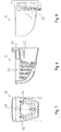
- Fig. 7
- die Toilettenschüssel nach Fig. 6 in Rückansicht,
- Fig. 8
- die Toilettenschüssel gemäß Fig. 6 in Seitenansicht,
- Fig. 9
- einen Längsschnitt durch in einen Randbereich einer Toilettenschüssel eingelassene Düse und
- Fig. 10
- eine Draufsicht auf die Düse gemäß Fig. 9 .
Claims (10)
- Toilettenschüssel (10), insbesondere bestimmt für eine Vakuum-Toilettenanlage, mit im oberen Rand der Toilettenschüssel angeordneter Spüldüse (22, 23) zum Abgeben von die Toilettenschüssel innenflächig besprühender bzw. bespülender Flüssigkeit, wobei die Spüldüse (22, 23) einen scheibenförmigen sich entlang der Toilettenschüsselinnenfläche (24) erstreckenden ersten Abschnitt (44) mit einem Austrittsschlitz (50) bogenförmigen Verlaufs sowie einen in einer Aufnahme der Toilettenschüssel sich erstreckenden bzw. fixierten einen Kanal (48) aufweisenden zweiten Abschnitt (46) umfasst, über den die Flüssigkeit zu dem Austrittsschlitz strömt,
dadurch gekennzeichnet, dass der Austrittsschlitz (50) der Spüldüse (22, 23) in seinem jeweiligen Endbereich in eine Bohrung (56, 58) übergeht, deren Durchmesser D größer als der Austrittsschlitz in seiner Breite S ist, dass die Bohrungen einen Winkel α mit 140° ≤ α ≤ 180° einschließen und dass die von dem Austrittsschlitz aufgespannte erste Ebene in Richtung der Innenfläche (24) der Toilettenschüssel (10) geneigt verläuft. - Toilettenschüssel nach Anspruch 1,
dadurch gekennzeichnet, dass die Bohrungen (56, 58) von dem den zweiten Abschnitt (46) durchsetzenden Kanal (48) ausgehen und insbesondere den in dem zweiten Abschnitt verlaufenden Kanal (48) außermittig, vorzugsweise in einem Randbereich schneiden. - Toilettenschüssel nach Anspruch 2,
dadurch gekennzeichnet, dass die Bohrungen (56, 58) den in dem zweiten Abschnitt (46) verlaufenden Kanal (48) in dessen schlitzfernliegendem Randbereich (64) schneiden. - Toilettenschüssel nach Anspruch 1,
dadurch gekennzeichnet, dass der erste Abschnitt (44) der Spüldüse (22, 23) bzw. dessen Innenfläche (60) eine zweite Ebene aufspannt und dass die von dem Austrittsschlitz aufgespannte erste Ebene und die zweite Ebene geneigt zueinander verlaufen. - Toilettenschüssel nach Anspruch 4,
dadurch gekennzeichnet, dass die erste und die zweite Ebene einen Winkel β von 4° < β < 8°, insbesondere 6° < β < 6,5° einschließen. - Toilettenschüssel nach Anspruch 1,
dadurch gekennzeichnet, dass die Spüldüse (22, 23) die Form eines Pilzes aufweist, dessen Hut der erste Abschnitt (44) und dessen Stiel der zweite Abschnitt (46) ist. - Toilettenschüssel nach zumindest Anspruch 1,
dadurch gekennzeichnet, dass am Toilettenschüsselrand (20) insgesamt zwei Spüldüsen (22, 23) diametral zueinander angeordnet sind. - Toilettenschüssel nach zumindest Anspruch 1,
dadurch gekennzeichnet, dass jeweils eine Spüldüse (22, 23) mittig in einem Seitenrandbereich der Toilettenschüssel (10) angeordnet ist. - Toilettenschüssel nach zumindest Anspruch 1,
dadurch gekennzeichnet, dass der erste Abschnitt (44) der Spüldüse (22, 23) mit seiner Innenfläche (60) zumindest bereichsweise an einer Innenfläche (24) der Toilettenschüssel (10) anliegt. - Toilettenschüssel nach zumindest Anspruch 1,
dadurch gekennzeichnet, dass der Durchmesser D der Bohrung (56, 58) zu der Breite S des Austrittsschlitzes (50) sich verhält wie 1,5 S < D < 2,5 S, insbesondere D in etwa 1,8 S ist, und/oder dass der Winkel α zwischen den Bohrungen (56, 58) sich beläuft auf 160° ≤ α ≤ 165°.
Applications Claiming Priority (3)
| Application Number | Priority Date | Filing Date | Title |
|---|---|---|---|
| DE10002070A DE10002070C2 (de) | 2000-01-18 | 2000-01-18 | Toilettenschüssel |
| DE10002070 | 2000-01-18 | ||
| EP01100666A EP1120500B1 (de) | 2000-01-18 | 2001-01-11 | Toilettenschüssel |
Related Parent Applications (1)
| Application Number | Title | Priority Date | Filing Date |
|---|---|---|---|
| EP01100666A Division EP1120500B1 (de) | 2000-01-18 | 2001-01-11 | Toilettenschüssel |
Publications (2)
| Publication Number | Publication Date |
|---|---|
| EP1493874A1 true EP1493874A1 (de) | 2005-01-05 |
| EP1493874B1 EP1493874B1 (de) | 2007-10-03 |
Family
ID=7627987
Family Applications (2)
| Application Number | Title | Priority Date | Filing Date |
|---|---|---|---|
| EP01100666A Expired - Lifetime EP1120500B1 (de) | 2000-01-18 | 2001-01-11 | Toilettenschüssel |
| EP04015717A Expired - Lifetime EP1493874B1 (de) | 2000-01-18 | 2001-01-11 | Toilettenschüssel |
Family Applications Before (1)
| Application Number | Title | Priority Date | Filing Date |
|---|---|---|---|
| EP01100666A Expired - Lifetime EP1120500B1 (de) | 2000-01-18 | 2001-01-11 | Toilettenschüssel |
Country Status (3)
| Country | Link |
|---|---|
| EP (2) | EP1120500B1 (de) |
| AT (2) | ATE374870T1 (de) |
| DE (4) | DE10065985B4 (de) |
Cited By (3)
| Publication number | Priority date | Publication date | Assignee | Title |
|---|---|---|---|---|
| RU2359088C1 (ru) * | 2007-12-17 | 2009-06-20 | Общество с ограниченной ответственностью "Промышленные вакуумные системы" | Сопло для обмыва внутренней поверхности чаши унитаза |
| RU2436905C2 (ru) * | 2009-10-16 | 2011-12-20 | Общество с ограниченной ответственностью "Промышленные вакуумные системы" | Сопло для обмыва внутренней поверхности чаши унитаза |
| CN101775838B (zh) * | 2009-12-29 | 2012-06-27 | 福州百特节能科技有限公司 | 无臭节能减排马桶 |
Families Citing this family (5)
| Publication number | Priority date | Publication date | Assignee | Title |
|---|---|---|---|---|
| FI116952B (fi) * | 2005-01-25 | 2006-04-13 | Evac Int Oy | Alipaineviemärijärjestelmä |
| DE102006010569A1 (de) * | 2006-03-06 | 2007-09-20 | Roediger Vakuum- Und Haustechnik Gmbh | Unterdruckabwassereinrichtung |
| CN101265720B (zh) * | 2007-03-15 | 2010-12-22 | 陈云河 | 微水·止逆便器 |
| PT2604761E (pt) * | 2011-12-14 | 2015-05-13 | Geberit Int Ag | Vaso sanitário |
| DE102012211655A1 (de) * | 2012-07-04 | 2014-01-09 | Tece Gmbh | Dusch - WC |
Citations (8)
| Publication number | Priority date | Publication date | Assignee | Title |
|---|---|---|---|---|
| DE1061559B (de) * | 1955-08-05 | 1959-07-16 | Dorman Sprayer Company Ltd | Spruehduese fuer land- und forstwirtschaftliche Zwecke |
| DE2529169A1 (de) | 1974-07-04 | 1976-01-22 | Ifoe Ab | Vorrichtung zur verteilung von spuelwasser in einer klosettschuessel |
| US4075718A (en) | 1975-04-03 | 1978-02-28 | Hargraves William J | Nozzle flush system |
| EP0019449A1 (de) | 1979-05-16 | 1980-11-26 | Ideal-Standard Gmbh | Spülwasserverteiler für ein Wasserklosettbecken |
| US4404696A (en) * | 1981-08-10 | 1983-09-20 | International Water Saving Systems, Inc. | Fluid velocity assist |
| DE8619586U1 (de) | 1986-07-22 | 1986-09-11 | Siemens AG, 1000 Berlin und 8000 München | Vorrichtung zum Verriegeln eines Überwachungsgeräts für eine Leuchtdiode |
| US5715544A (en) | 1995-11-22 | 1998-02-10 | Thetford Corporation | Toilet with improved flush nozzle |
| DE29700985U1 (de) | 1997-01-22 | 1998-05-20 | Sanivac Vakuumtechnik GmbH, 22880 Wedel | Vakuumtoilette |
Family Cites Families (5)
| Publication number | Priority date | Publication date | Assignee | Title |
|---|---|---|---|---|
| US2116527A (en) * | 1934-12-07 | 1938-05-10 | John Douglas Company | Flush bowl |
| US2080073A (en) * | 1935-12-20 | 1937-05-11 | Walter H Finley | Overflow preventing apparatus |
| DE1976997U (de) * | 1967-10-03 | 1968-01-11 | Annawerk Keramische Betr E G M | Wasserklosettbecken mit spuelwasserverteiler. |
| DE8619584U1 (de) * | 1986-07-22 | 1986-09-18 | Bitter, Wilfried H., 4410 Warendorf | Wasserklosett |
| US6012678A (en) * | 1998-01-26 | 2000-01-11 | The Boeing Company | Galley vacuum waste disposal system |
-
2000
- 2000-01-18 DE DE10065985A patent/DE10065985B4/de not_active Expired - Fee Related
- 2000-01-18 DE DE10002070A patent/DE10002070C2/de not_active Expired - Fee Related
-
2001
- 2001-01-11 AT AT04015717T patent/ATE374870T1/de not_active IP Right Cessation
- 2001-01-11 DE DE50113098T patent/DE50113098D1/de not_active Expired - Lifetime
- 2001-01-11 EP EP01100666A patent/EP1120500B1/de not_active Expired - Lifetime
- 2001-01-11 AT AT01100666T patent/ATE364111T1/de active
- 2001-01-11 DE DE50112579T patent/DE50112579D1/de not_active Expired - Lifetime
- 2001-01-11 EP EP04015717A patent/EP1493874B1/de not_active Expired - Lifetime
Patent Citations (8)
| Publication number | Priority date | Publication date | Assignee | Title |
|---|---|---|---|---|
| DE1061559B (de) * | 1955-08-05 | 1959-07-16 | Dorman Sprayer Company Ltd | Spruehduese fuer land- und forstwirtschaftliche Zwecke |
| DE2529169A1 (de) | 1974-07-04 | 1976-01-22 | Ifoe Ab | Vorrichtung zur verteilung von spuelwasser in einer klosettschuessel |
| US4075718A (en) | 1975-04-03 | 1978-02-28 | Hargraves William J | Nozzle flush system |
| EP0019449A1 (de) | 1979-05-16 | 1980-11-26 | Ideal-Standard Gmbh | Spülwasserverteiler für ein Wasserklosettbecken |
| US4404696A (en) * | 1981-08-10 | 1983-09-20 | International Water Saving Systems, Inc. | Fluid velocity assist |
| DE8619586U1 (de) | 1986-07-22 | 1986-09-11 | Siemens AG, 1000 Berlin und 8000 München | Vorrichtung zum Verriegeln eines Überwachungsgeräts für eine Leuchtdiode |
| US5715544A (en) | 1995-11-22 | 1998-02-10 | Thetford Corporation | Toilet with improved flush nozzle |
| DE29700985U1 (de) | 1997-01-22 | 1998-05-20 | Sanivac Vakuumtechnik GmbH, 22880 Wedel | Vakuumtoilette |
Cited By (3)
| Publication number | Priority date | Publication date | Assignee | Title |
|---|---|---|---|---|
| RU2359088C1 (ru) * | 2007-12-17 | 2009-06-20 | Общество с ограниченной ответственностью "Промышленные вакуумные системы" | Сопло для обмыва внутренней поверхности чаши унитаза |
| RU2436905C2 (ru) * | 2009-10-16 | 2011-12-20 | Общество с ограниченной ответственностью "Промышленные вакуумные системы" | Сопло для обмыва внутренней поверхности чаши унитаза |
| CN101775838B (zh) * | 2009-12-29 | 2012-06-27 | 福州百特节能科技有限公司 | 无臭节能减排马桶 |
Also Published As
| Publication number | Publication date |
|---|---|
| DE10002070C2 (de) | 2001-12-20 |
| DE10002070A1 (de) | 2001-08-09 |
| EP1120500A3 (de) | 2001-10-31 |
| ATE364111T1 (de) | 2007-06-15 |
| DE10065985A1 (de) | 2002-08-14 |
| EP1120500B1 (de) | 2007-06-06 |
| EP1120500A2 (de) | 2001-08-01 |
| ATE374870T1 (de) | 2007-10-15 |
| DE50112579D1 (de) | 2007-07-19 |
| EP1493874B1 (de) | 2007-10-03 |
| DE10065985B4 (de) | 2005-05-25 |
| DE50113098D1 (de) | 2007-11-15 |
Similar Documents
| Publication | Publication Date | Title |
|---|---|---|
| EP2192852B1 (de) | Geschirrspüler | |
| WO2006136215A2 (de) | Spülwasserführung für ein toilettenbecken | |
| DE202010002777U1 (de) | Ablaufgarnitur mit Reinigungsöffnung | |
| EP1493874B1 (de) | Toilettenschüssel | |
| DE60222170T2 (de) | Abgabevorrichtung für flüssige wirkstoffe für wc-becken | |
| EP1862602B1 (de) | Becken mit verdecktem Überlauf und zugehöriger Ablaufgarnitur | |
| AT5032U1 (de) | Absaugesiphon für eine spüleinrichtung | |
| EP0185109B1 (de) | Geruchsverschluss | |
| EP1651821A1 (de) | Urinal | |
| EP2666917B1 (de) | WC mit Geruchsabsaugeinrichtung | |
| EP1832689A1 (de) | Unterdruckabwassereinrichtung | |
| DE2929579A1 (de) | Wasserzulaufvorrichtung fuer haushaltgeschirrspuelmaschinen | |
| EP0737784A1 (de) | Ablaufventil für einen Spülkasten | |
| DE2241763A1 (de) | Einlaufgarnitur fuer spuelkaesten | |
| DE102018208751B4 (de) | Flüssigkeitsbehälter | |
| EP1001097B1 (de) | Spülwasserverteiler | |
| EP2063753B1 (de) | Bodendüse für hartböden | |
| EP3139991A1 (de) | Verbindungseinrichtung für einen kathether, insbesondere einen peripheren venenkatheter | |
| DE69100723T2 (de) | Wasserstandsregelvorrichtung in einer Haushaltsmaschine und Maschine ausgerüstet mit einer solchen Vorrichtung. | |
| EP2073681A1 (de) | Bodendüse für hartböden | |
| DE60121660T2 (de) | Taktweise bearbeitendes Spülventil | |
| EP0757135A1 (de) | Spülkasten | |
| DE900199C (de) | Verfahren zur Desinfizierung von Spuelaborten, Pissoiranlagen und aehnlichen sanitaeren Einrichtungen sowie Fluessigkeitszusetzapparat zur Ausfuehrung des Verfahrens | |
| DE1658263A1 (de) | Geruchsbeseitigung und Reinigung von Toiletten | |
| EP0492090B1 (de) | Haushalt-Geschirrspülmaschine |
Legal Events
| Date | Code | Title | Description |
|---|---|---|---|
| PUAI | Public reference made under article 153(3) epc to a published international application that has entered the european phase |
Free format text: ORIGINAL CODE: 0009012 |
|
| AC | Divisional application: reference to earlier application |
Ref document number: 1120500 Country of ref document: EP Kind code of ref document: P |
|
| AK | Designated contracting states |
Kind code of ref document: A1 Designated state(s): AT BE CH CY DE DK ES FI FR GB GR IE IT LI LU MC NL PT SE TR |
|
| 17P | Request for examination filed |
Effective date: 20050429 |
|
| AKX | Designation fees paid |
Designated state(s): AT BE CH CY DE DK ES FI FR GB GR IE IT LI LU MC NL PT SE TR |
|
| 17Q | First examination report despatched |
Effective date: 20060726 |
|
| GRAP | Despatch of communication of intention to grant a patent |
Free format text: ORIGINAL CODE: EPIDOSNIGR1 |
|
| GRAS | Grant fee paid |
Free format text: ORIGINAL CODE: EPIDOSNIGR3 |
|
| GRAA | (expected) grant |
Free format text: ORIGINAL CODE: 0009210 |
|
| AC | Divisional application: reference to earlier application |
Ref document number: 1120500 Country of ref document: EP Kind code of ref document: P |
|
| AK | Designated contracting states |
Kind code of ref document: B1 Designated state(s): AT BE CH CY DE DK ES FI FR GB GR IE IT LI LU MC NL PT SE TR |
|
| REG | Reference to a national code |
Ref country code: GB Ref legal event code: FG4D Free format text: NOT ENGLISH |
|
| REG | Reference to a national code |
Ref country code: CH Ref legal event code: EP |
|
| REG | Reference to a national code |
Ref country code: IE Ref legal event code: FG4D Free format text: LANGUAGE OF EP DOCUMENT: GERMAN |
|
| REF | Corresponds to: |
Ref document number: 50113098 Country of ref document: DE Date of ref document: 20071115 Kind code of ref document: P |
|
| RAP2 | Party data changed (patent owner data changed or rights of a patent transferred) |
Owner name: ROEDIGER VACUUM GMBH |
|
| NLT2 | Nl: modifications (of names), taken from the european patent patent bulletin |
Owner name: ROEDIGER VACUUM GMBH Effective date: 20071212 |
|
| NLV1 | Nl: lapsed or annulled due to failure to fulfill the requirements of art. 29p and 29m of the patents act | ||
| PG25 | Lapsed in a contracting state [announced via postgrant information from national office to epo] |
Ref country code: SE Free format text: LAPSE BECAUSE OF FAILURE TO SUBMIT A TRANSLATION OF THE DESCRIPTION OR TO PAY THE FEE WITHIN THE PRESCRIBED TIME-LIMIT Effective date: 20080103 Ref country code: NL Free format text: LAPSE BECAUSE OF FAILURE TO SUBMIT A TRANSLATION OF THE DESCRIPTION OR TO PAY THE FEE WITHIN THE PRESCRIBED TIME-LIMIT Effective date: 20071003 Ref country code: ES Free format text: LAPSE BECAUSE OF FAILURE TO SUBMIT A TRANSLATION OF THE DESCRIPTION OR TO PAY THE FEE WITHIN THE PRESCRIBED TIME-LIMIT Effective date: 20080114 |
|
| PG25 | Lapsed in a contracting state [announced via postgrant information from national office to epo] |
Ref country code: PT Free format text: LAPSE BECAUSE OF FAILURE TO SUBMIT A TRANSLATION OF THE DESCRIPTION OR TO PAY THE FEE WITHIN THE PRESCRIBED TIME-LIMIT Effective date: 20080303 |
|
| REG | Reference to a national code |
Ref country code: IE Ref legal event code: FD4D |
|
| ET | Fr: translation filed | ||
| BERE | Be: lapsed |
Owner name: ROEDIGER VAKUUM- UND HAUSTECHNIK G.M.B.H. Effective date: 20080131 |
|
| PG25 | Lapsed in a contracting state [announced via postgrant information from national office to epo] |
Ref country code: DK Free format text: LAPSE BECAUSE OF FAILURE TO SUBMIT A TRANSLATION OF THE DESCRIPTION OR TO PAY THE FEE WITHIN THE PRESCRIBED TIME-LIMIT Effective date: 20071003 |
|
| PLBE | No opposition filed within time limit |
Free format text: ORIGINAL CODE: 0009261 |
|
| STAA | Information on the status of an ep patent application or granted ep patent |
Free format text: STATUS: NO OPPOSITION FILED WITHIN TIME LIMIT |
|
| PG25 | Lapsed in a contracting state [announced via postgrant information from national office to epo] |
Ref country code: MC Free format text: LAPSE BECAUSE OF NON-PAYMENT OF DUE FEES Effective date: 20080131 |
|
| REG | Reference to a national code |
Ref country code: CH Ref legal event code: PL |
|
| 26N | No opposition filed |
Effective date: 20080704 |
|
| PG25 | Lapsed in a contracting state [announced via postgrant information from national office to epo] |
Ref country code: LI Free format text: LAPSE BECAUSE OF NON-PAYMENT OF DUE FEES Effective date: 20080131 Ref country code: IE Free format text: LAPSE BECAUSE OF FAILURE TO SUBMIT A TRANSLATION OF THE DESCRIPTION OR TO PAY THE FEE WITHIN THE PRESCRIBED TIME-LIMIT Effective date: 20071003 Ref country code: CH Free format text: LAPSE BECAUSE OF NON-PAYMENT OF DUE FEES Effective date: 20080131 |
|
| PG25 | Lapsed in a contracting state [announced via postgrant information from national office to epo] |
Ref country code: GR Free format text: LAPSE BECAUSE OF FAILURE TO SUBMIT A TRANSLATION OF THE DESCRIPTION OR TO PAY THE FEE WITHIN THE PRESCRIBED TIME-LIMIT Effective date: 20080104 |
|
| PG25 | Lapsed in a contracting state [announced via postgrant information from national office to epo] |
Ref country code: BE Free format text: LAPSE BECAUSE OF NON-PAYMENT OF DUE FEES Effective date: 20080131 |
|
| PG25 | Lapsed in a contracting state [announced via postgrant information from national office to epo] |
Ref country code: AT Free format text: LAPSE BECAUSE OF NON-PAYMENT OF DUE FEES Effective date: 20080111 |
|
| PG25 | Lapsed in a contracting state [announced via postgrant information from national office to epo] |
Ref country code: CY Free format text: LAPSE BECAUSE OF FAILURE TO SUBMIT A TRANSLATION OF THE DESCRIPTION OR TO PAY THE FEE WITHIN THE PRESCRIBED TIME-LIMIT Effective date: 20071003 |
|
| PG25 | Lapsed in a contracting state [announced via postgrant information from national office to epo] |
Ref country code: FI Free format text: LAPSE BECAUSE OF FAILURE TO SUBMIT A TRANSLATION OF THE DESCRIPTION OR TO PAY THE FEE WITHIN THE PRESCRIBED TIME-LIMIT Effective date: 20071003 |
|
| PG25 | Lapsed in a contracting state [announced via postgrant information from national office to epo] |
Ref country code: LU Free format text: LAPSE BECAUSE OF NON-PAYMENT OF DUE FEES Effective date: 20080111 |
|
| PG25 | Lapsed in a contracting state [announced via postgrant information from national office to epo] |
Ref country code: TR Free format text: LAPSE BECAUSE OF FAILURE TO SUBMIT A TRANSLATION OF THE DESCRIPTION OR TO PAY THE FEE WITHIN THE PRESCRIBED TIME-LIMIT Effective date: 20071003 |
|
| REG | Reference to a national code |
Ref country code: FR Ref legal event code: PLFP Year of fee payment: 16 |
|
| PGFP | Annual fee paid to national office [announced via postgrant information from national office to epo] |
Ref country code: DE Payment date: 20160127 Year of fee payment: 16 Ref country code: IT Payment date: 20160127 Year of fee payment: 16 |
|
| PGFP | Annual fee paid to national office [announced via postgrant information from national office to epo] |
Ref country code: FR Payment date: 20160121 Year of fee payment: 16 Ref country code: GB Payment date: 20160120 Year of fee payment: 16 |
|
| REG | Reference to a national code |
Ref country code: DE Ref legal event code: R119 Ref document number: 50113098 Country of ref document: DE |
|
| GBPC | Gb: european patent ceased through non-payment of renewal fee |
Effective date: 20170111 |
|
| REG | Reference to a national code |
Ref country code: FR Ref legal event code: ST Effective date: 20170929 |
|
| PG25 | Lapsed in a contracting state [announced via postgrant information from national office to epo] |
Ref country code: FR Free format text: LAPSE BECAUSE OF NON-PAYMENT OF DUE FEES Effective date: 20170131 |
|
| PG25 | Lapsed in a contracting state [announced via postgrant information from national office to epo] |
Ref country code: DE Free format text: LAPSE BECAUSE OF NON-PAYMENT OF DUE FEES Effective date: 20170801 Ref country code: GB Free format text: LAPSE BECAUSE OF NON-PAYMENT OF DUE FEES Effective date: 20170111 |
|
| PG25 | Lapsed in a contracting state [announced via postgrant information from national office to epo] |
Ref country code: IT Free format text: LAPSE BECAUSE OF NON-PAYMENT OF DUE FEES Effective date: 20170111 |