EP1493901B1 - Leitschaufelstufe eines Verdichters für einen Luftfahrzeugsmotor - Google Patents
Leitschaufelstufe eines Verdichters für einen Luftfahrzeugsmotor Download PDFInfo
- Publication number
- EP1493901B1 EP1493901B1 EP04291500A EP04291500A EP1493901B1 EP 1493901 B1 EP1493901 B1 EP 1493901B1 EP 04291500 A EP04291500 A EP 04291500A EP 04291500 A EP04291500 A EP 04291500A EP 1493901 B1 EP1493901 B1 EP 1493901B1
- Authority
- EP
- European Patent Office
- Prior art keywords
- stator according
- blades
- ferrule
- inner ferrule
- rigid members
- Prior art date
- Legal status (The legal status is an assumption and is not a legal conclusion. Google has not performed a legal analysis and makes no representation as to the accuracy of the status listed.)
- Expired - Lifetime
Links
- 239000004642 Polyimide Substances 0.000 claims description 14
- 229920001721 polyimide Polymers 0.000 claims description 14
- 239000000853 adhesive Substances 0.000 claims description 11
- 230000001070 adhesive effect Effects 0.000 claims description 11
- 239000004568 cement Substances 0.000 claims description 10
- 239000004744 fabric Substances 0.000 claims description 5
- 239000006260 foam Substances 0.000 claims description 5
- RTAQQCXQSZGOHL-UHFFFAOYSA-N Titanium Chemical compound [Ti] RTAQQCXQSZGOHL-UHFFFAOYSA-N 0.000 claims description 4
- XAGFODPZIPBFFR-UHFFFAOYSA-N aluminium Chemical compound [Al] XAGFODPZIPBFFR-UHFFFAOYSA-N 0.000 claims description 3
- 238000010894 electron beam technology Methods 0.000 claims description 3
- 239000011152 fibreglass Substances 0.000 claims description 3
- 239000010936 titanium Substances 0.000 claims description 3
- 229910052719 titanium Inorganic materials 0.000 claims description 3
- 229910000838 Al alloy Inorganic materials 0.000 claims description 2
- 229920000049 Carbon (fiber) Polymers 0.000 claims description 2
- 239000004411 aluminium Substances 0.000 claims description 2
- VNWKTOKETHGBQD-UHFFFAOYSA-N methane Chemical compound C VNWKTOKETHGBQD-UHFFFAOYSA-N 0.000 claims description 2
- 238000003466 welding Methods 0.000 claims description 2
- 229910000861 Mg alloy Inorganic materials 0.000 claims 1
- 230000006866 deterioration Effects 0.000 claims 1
- 239000003292 glue Substances 0.000 description 7
- 238000005219 brazing Methods 0.000 description 4
- 238000000034 method Methods 0.000 description 4
- FYYHWMGAXLPEAU-UHFFFAOYSA-N Magnesium Chemical compound [Mg] FYYHWMGAXLPEAU-UHFFFAOYSA-N 0.000 description 3
- 239000010408 film Substances 0.000 description 3
- 229910052782 aluminium Inorganic materials 0.000 description 2
- 229920001971 elastomer Polymers 0.000 description 2
- 239000000806 elastomer Substances 0.000 description 2
- 229910052749 magnesium Inorganic materials 0.000 description 2
- 239000011777 magnesium Substances 0.000 description 2
- 229920002379 silicone rubber Polymers 0.000 description 2
- 239000010409 thin film Substances 0.000 description 2
- 241000195940 Bryophyta Species 0.000 description 1
- OKTJSMMVPCPJKN-UHFFFAOYSA-N Carbon Chemical compound [C] OKTJSMMVPCPJKN-UHFFFAOYSA-N 0.000 description 1
- 241001639412 Verres Species 0.000 description 1
- 229910045601 alloy Inorganic materials 0.000 description 1
- 239000000956 alloy Substances 0.000 description 1
- 229910052799 carbon Inorganic materials 0.000 description 1
- 239000004917 carbon fiber Substances 0.000 description 1
- 230000015556 catabolic process Effects 0.000 description 1
- 230000000295 complement effect Effects 0.000 description 1
- 239000000470 constituent Substances 0.000 description 1
- 230000007423 decrease Effects 0.000 description 1
- 238000006731 degradation reaction Methods 0.000 description 1
- 238000010438 heat treatment Methods 0.000 description 1
- 238000004519 manufacturing process Methods 0.000 description 1
- 239000000463 material Substances 0.000 description 1
- 229910052751 metal Inorganic materials 0.000 description 1
- 239000002184 metal Substances 0.000 description 1
- 150000002739 metals Chemical class 0.000 description 1
- 239000000203 mixture Substances 0.000 description 1
- 235000011929 mousse Nutrition 0.000 description 1
- 229920000620 organic polymer Polymers 0.000 description 1
- 229920001296 polysiloxane Polymers 0.000 description 1
- 230000000135 prohibitive effect Effects 0.000 description 1
- 238000006467 substitution reaction Methods 0.000 description 1
- 210000001519 tissue Anatomy 0.000 description 1
Images

Classifications
-
- F—MECHANICAL ENGINEERING; LIGHTING; HEATING; WEAPONS; BLASTING
- F04—POSITIVE - DISPLACEMENT MACHINES FOR LIQUIDS; PUMPS FOR LIQUIDS OR ELASTIC FLUIDS
- F04D—NON-POSITIVE-DISPLACEMENT PUMPS
- F04D29/00—Details, component parts, or accessories
- F04D29/02—Selection of particular materials
- F04D29/023—Selection of particular materials especially adapted for elastic fluid pumps
-
- F—MECHANICAL ENGINEERING; LIGHTING; HEATING; WEAPONS; BLASTING
- F01—MACHINES OR ENGINES IN GENERAL; ENGINE PLANTS IN GENERAL; STEAM ENGINES
- F01D—NON-POSITIVE DISPLACEMENT MACHINES OR ENGINES, e.g. STEAM TURBINES
- F01D9/00—Stators
- F01D9/02—Nozzles; Nozzle boxes; Stator blades; Guide conduits, e.g. individual nozzles
- F01D9/04—Nozzles; Nozzle boxes; Stator blades; Guide conduits, e.g. individual nozzles forming ring or sector
- F01D9/042—Nozzles; Nozzle boxes; Stator blades; Guide conduits, e.g. individual nozzles forming ring or sector fixing blades to stators
-
- F—MECHANICAL ENGINEERING; LIGHTING; HEATING; WEAPONS; BLASTING
- F04—POSITIVE - DISPLACEMENT MACHINES FOR LIQUIDS; PUMPS FOR LIQUIDS OR ELASTIC FLUIDS
- F04D—NON-POSITIVE-DISPLACEMENT PUMPS
- F04D29/00—Details, component parts, or accessories
- F04D29/40—Casings; Connections of working fluid
- F04D29/52—Casings; Connections of working fluid for axial pumps
- F04D29/54—Fluid-guiding means, e.g. diffusers
- F04D29/541—Specially adapted for elastic fluid pumps
- F04D29/542—Bladed diffusers
-
- F—MECHANICAL ENGINEERING; LIGHTING; HEATING; WEAPONS; BLASTING
- F05—INDEXING SCHEMES RELATING TO ENGINES OR PUMPS IN VARIOUS SUBCLASSES OF CLASSES F01-F04
- F05D—INDEXING SCHEME FOR ASPECTS RELATING TO NON-POSITIVE-DISPLACEMENT MACHINES OR ENGINES, GAS-TURBINES OR JET-PROPULSION PLANTS
- F05D2230/00—Manufacture
- F05D2230/20—Manufacture essentially without removing material
- F05D2230/23—Manufacture essentially without removing material by permanently joining parts together
-
- F—MECHANICAL ENGINEERING; LIGHTING; HEATING; WEAPONS; BLASTING
- F05—INDEXING SCHEMES RELATING TO ENGINES OR PUMPS IN VARIOUS SUBCLASSES OF CLASSES F01-F04
- F05D—INDEXING SCHEME FOR ASPECTS RELATING TO NON-POSITIVE-DISPLACEMENT MACHINES OR ENGINES, GAS-TURBINES OR JET-PROPULSION PLANTS
- F05D2300/00—Materials; Properties thereof
- F05D2300/40—Organic materials
- F05D2300/43—Synthetic polymers, e.g. plastics; Rubber
- F05D2300/434—Polyimides, e.g. AURUM
-
- F—MECHANICAL ENGINEERING; LIGHTING; HEATING; WEAPONS; BLASTING
- F05—INDEXING SCHEMES RELATING TO ENGINES OR PUMPS IN VARIOUS SUBCLASSES OF CLASSES F01-F04
- F05D—INDEXING SCHEME FOR ASPECTS RELATING TO NON-POSITIVE-DISPLACEMENT MACHINES OR ENGINES, GAS-TURBINES OR JET-PROPULSION PLANTS
- F05D2300/00—Materials; Properties thereof
- F05D2300/60—Properties or characteristics given to material by treatment or manufacturing
- F05D2300/603—Composites; e.g. fibre-reinforced
-
- Y—GENERAL TAGGING OF NEW TECHNOLOGICAL DEVELOPMENTS; GENERAL TAGGING OF CROSS-SECTIONAL TECHNOLOGIES SPANNING OVER SEVERAL SECTIONS OF THE IPC; TECHNICAL SUBJECTS COVERED BY FORMER USPC CROSS-REFERENCE ART COLLECTIONS [XRACs] AND DIGESTS
- Y02—TECHNOLOGIES OR APPLICATIONS FOR MITIGATION OR ADAPTATION AGAINST CLIMATE CHANGE
- Y02T—CLIMATE CHANGE MITIGATION TECHNOLOGIES RELATED TO TRANSPORTATION
- Y02T50/00—Aeronautics or air transport
- Y02T50/60—Efficient propulsion technologies, e.g. for aircraft
-
- Y—GENERAL TAGGING OF NEW TECHNOLOGICAL DEVELOPMENTS; GENERAL TAGGING OF CROSS-SECTIONAL TECHNOLOGIES SPANNING OVER SEVERAL SECTIONS OF THE IPC; TECHNICAL SUBJECTS COVERED BY FORMER USPC CROSS-REFERENCE ART COLLECTIONS [XRACs] AND DIGESTS
- Y10—TECHNICAL SUBJECTS COVERED BY FORMER USPC
- Y10T—TECHNICAL SUBJECTS COVERED BY FORMER US CLASSIFICATION
- Y10T29/00—Metal working
- Y10T29/49—Method of mechanical manufacture
- Y10T29/49316—Impeller making
- Y10T29/4932—Turbomachine making
- Y10T29/49323—Assembling fluid flow directing devices, e.g., stators, diaphragms, nozzles
-
- Y—GENERAL TAGGING OF NEW TECHNOLOGICAL DEVELOPMENTS; GENERAL TAGGING OF CROSS-SECTIONAL TECHNOLOGIES SPANNING OVER SEVERAL SECTIONS OF THE IPC; TECHNICAL SUBJECTS COVERED BY FORMER USPC CROSS-REFERENCE ART COLLECTIONS [XRACs] AND DIGESTS
- Y10—TECHNICAL SUBJECTS COVERED BY FORMER USPC
- Y10T—TECHNICAL SUBJECTS COVERED BY FORMER US CLASSIFICATION
- Y10T29/00—Metal working
- Y10T29/49—Method of mechanical manufacture
- Y10T29/49826—Assembling or joining
- Y10T29/49885—Assembling or joining with coating before or during assembling
Definitions
- the invention relates to an engine compressor rectifier aeronautic including inner ferrule, ferrule outside and a multiplicity of blades distributed in the circumferential direction extending radially from the ferrule inner to outer shell, each dawn through a corresponding opening in the ferrule inside and being attached to it by means of a waterproof cement containing an organic polymer adhesive.
- US 6,431,830 described a rectifier in which blades are attached to the inner shell by brazing.
- Brazing solution is not always applicable, function of the constituent materials of the blades and the ferrule.
- the Brazing should be done at very high temperatures leading to prohibitive deformations.
- the object of the invention is to overcome the above disadvantages known fastening techniques.
- glued joints can be used for 1000 hours at nearby temperatures 300 ° C.
- the invention aims in particular at a rectifier of the kind defined in introduction, and provides that said adhesive is based on polyimide.
- Polyimide adhesives resist in a sustainable way to the atmospheres of engine compressors aeronautical. It is possible to choose such an adhesive in function of the intended operating temperature, some of them supporting temperatures of the order of 300 ° C.
- FIG. 1 is a partial view in axial half-section of a compressor stage to which the invention applies, showing an inner ferrule, an outer ferrule and a dawn attached to them.
- Figure 2 is an enlarged portion of Figure 1, showing the inner ferrule and the neighboring dawn regions of it.
- FIG. 3 is a partial view of the internal face of the inner ferrule, developed flat in imagination.
- FIG. 4 is a partial sectional view through a plane perpendicular to the motor axis, showing part of the inner ferrule and the corresponding blade root regions, attached to them according to a first mode of embodiment of the invention.
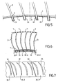
- FIG. 5 is a view similar to FIG. second embodiment of the invention.
- FIG. 6 is a view similar to FIGS. 4 and 5, relative to a third embodiment of the invention and showing furthermore the total length of the blades and part of the outer shell.
- FIG. 7 is a partial view of the internal face of the insert of Figure 6, developed flat in imagination.
- the rectifier stage shown in FIGS. 1 to 3 conventionally comprises an inner ferrule 1 and a outer shell 2, both fixed, and a series of blades straighteners 3 extending in a radial general direction from the inner ferrule to the outer ferrule.
- the blades 3 are distributed in the circumferential direction, usually in a uniform way.
- the inner ferrule 1 is pierced openings 4 whose shape is adapted to the profile of the blades. Each of them is crossed by a dawn 3, one of which end region 5 protrudes towards the axis of the motor beyond the opening 4 and therefore the face internal 6 of the shell 1.
- the blades 3 are fixed to the ferrule outer 2 for example by welds 7 made by electron beam.
- the internal face 6 of the inner ferrule 1 and the projecting regions 5 of the blades 3 are covered a flexible tablecloth made of several pieces of fabric 10-1, 10-2, 10-3 which connect to each other and overlap partially in the circumferential direction.
- the tablecloth flexible follows the inner contour defined by the face 6 and by regions 5 and therefore departs from ferrule 1 for forming pockets 11 in which are housed the regions 5.
- the piece of cloth 10-2 covers the end regions 5 of four blades 3, one of its marginal areas, noted 12-2, being covered by a marginal region 13-3 of piece 10-3, while its region marginally opposite 13-2 overlaps a marginal region 12-1 of the piece 10-1.
- Each of the marginal areas mentioned above is located between two neighboring blades.
- the flexible sheet delimits with the ferrule 1 and the blades 3 an annular volume 14 which is filled with a film of polyimide glue such marketed by Cytec Fiberite Inc. under the reference FM 680, this glue also fulfilling the gaps between the blades 3 and the periphery of the openings 4.
- the flexible ply 10-1, 10-2, 10-3 is advantageously formed fiberglass fabric or carbon impregnated with polyimide.
- the assigned volume to the adhesive composition is delimited towards the interior of the ferrule 1 by a multiplicity of alloy parts 20 of aluminum or magnesium, each of which is interposed between two neighboring blades 3.
- Each piece 2 presents in the plane of the figure a angular U-shaped profile whose bottom 21 is applied against the inner face 6 of the ferrule 1 and whose branches 22 are applied respectively to the two blades adjacent.
- a thin film of a polyimide-based glue such marketed by Cytec Fiberite Inc. under the reference FM 680, this glue also fulfilling the gaps between the blades and the periphery of the openings 4.
- a foam of polyimide such as that marketed by the company Cytec Fiberite Inc. under the reference FM 680-2.
- FIG. 5 The fixation of FIG. 5 can be carried out in the manner next.
- the inner face 6 of the ferrule is coated and the regions 5 of the blades of a thin film of glue and then inserting the parts 20 that are sized to be held in place by forced engagement prior to curing glue. This is done as in the example previous by heat treatment.
- the fixing method of FIGS. 6 and 7 differs from that of the FIG. 5 in that the hollow parts 20 are replaced by massive pieces 30-1, 30-2, 30-3 made in a polyimide foam such as that marketed by the Company Dupont de Nemours under the reference SF-0920, of a density of 0.3, each of which extends over an arc length multiple of the circumferential pitch of the blades, and is crossed by openings 31 for housing the projecting regions 5 of the blades. Two neighboring rooms are separated by an interval narrow 32 located between two neighboring blades. The assembly is done in the same way as in the case of Figure 5, the openings 31 can be dimensioned so as to allow parts 30-1, 30-2, 30-3 to be held in place by friction on the regions 5 of the blades.
- a polyimide foam such as that marketed by the Company Dupont de Nemours under the reference SF-0920, of a density of 0.3, each of which extends over an arc length multiple of the circumferential pitch of the blades, and is crossed
Landscapes
- Engineering & Computer Science (AREA)
- Mechanical Engineering (AREA)
- General Engineering & Computer Science (AREA)
- Structures Of Non-Positive Displacement Pumps (AREA)
- Adhesives Or Adhesive Processes (AREA)
Claims (19)
- Kompressorgleichrichter für einen Luftfahrzeugmotor, mit einer inneren Zwinge (1) und einer äußeren Zwinge (2) und einer Mehrzahl von Schaufeln (3), die in Umfangsrichtung verteilt angeordnet sind und sich radial von der inneren Zwinge zur äußeren Zwinge erstrecken, wobei eine jede Schaufel eine entsprechende Öffnung (4) durchquert, die in der inneren Zwinge ausgebildet ist, und an dieser letzteren mit Hilfe eines dichten Zements befestigt ist, der einen organischen Polymerklebstoff enthält, dadurch gekennzeichnet, dass der Klebstoff auf der Basis von Polyimid ist.
- Gleichrichter nach Anspruch 1, bei dem die innere Zwinge (1) und/oder die Schaufeln (3) aus Titan sind.
- Gleichrichter nach Anspruch 1 oder 2, bei dem die Endabschnitte (5) der Schaufeln (3) radial nach dem Inneren über die innere Zwinge hinaus vorspringen.
- Gleichrichter nach einem der vorhergehenden Ansprüche, bei dem ein Einsatz (10-1, 10-2, 10-3), der im Inneren der inneren Zwinge (1) und in der Nähe von dieser angeordnet ist, mit der inneren Zwinge und mit den Schaufeln (3) einen Raum (14) begrenzt, der mit dem Zement gefüllt ist.
- Gleichrichter nach Anspruch 4, bei dem der Einsatz in Form einer nachgiebigen Matte (10-1, 10-2, 10-3) ausgebildet ist.
- Gleichrichter nach Anspruch 5, bei dem die nachgiebige Matte gegenüber den Enden (5) der Schaufeln Taschen (11) bildet, die sich radial von der inneren Zwinge ausdehnen.
- Gleichrichter nach Anspruch 5 oder 6, bei dem die nachgiebige Matte aus mehreren Elementen (10-1, 10-2, 10-3) gebildet ist, die untereinander in Umfangsrichtung der inneren Zwinge mit teilweiser Überdeckung verbunden sind.
- Gleichrichter nach einem der Ansprüche 5 bis 7, bei dem die nachgiebige Matte ein Gewebe aus Glasfasern oder Karbonfasern ist, das mit Polyimid imprägniert ist.
- Gleichrichter nach Anspruch 4, bei dem der Einsatz in Form einer Mehrzahl von starren Elementen (20) gebildet ist.
- Gleichrichter nach Anspruch 9, verbunden mit dem Anspruch 3, bei dem ein jedes der starren Teile (20) zwischen die vorspringenden Abschnitte (5) von zwei aufeinander folgenden Schaufeln (3) gesetzt ist.
- Gleichrichter nach Anspruch 10, bei dem ein jedes der starren Teile (20) unter Zwang zwischen die vorspringende Abschnitte (5) montiert ist.
- Gleichrichter nach Anspruch 9, bei dem ein jedes der starren Teile (30-1, 30- 2, 30-3) sich über eine Bogenlänge erstreckt, die größer ist als die Umfangsteilung der Schaufeln (3).
- Gleichrichter nach Anspruch 12 in Verbindung mit Anspruch 3, bei dem die starren Teile Öffnungen (31) aufweisen, um die vorspringenden Abschnitte (5) der Schaufeln (3) aufzunehmen.
- Gleichrichter nach einem der Ansprüche 9 bis 13, bei dem die starren Teile (20) an der inneren Zwinge (1) durch den Zement befestigt sind.
- Gleichrichter nach einem der Ansprüche 9 bis 14, bei dem die starren Teile (20) aus einer Aluminium- oder Magnesiumlegierung gebildet sind.
- Gleichrichter nach einem der vorhergehenden Ansprüche, bei dem der Zement in Form eines Films vorliegt.
- Gleichrichter nach einem der Ansprüche 1 bis 15, bei dem der Zement in Form von Schaum vorliegt.
- Gleichrichter nach einem der vorhergehenden Ansprüche, bei dem der Klebstoff auf der Basis von Polyimid in der Lage ist, ohne Beschädigung einer Temperatur von ungefähr 300 °C beim Betrieb des Gleichrichters zu widerstehen.
- Gleichrichter nach einem der vorhergehenden Ansprüche, bei dem die Schaufeln (3) an der äußeren Zwinge (2) durch Schweißen (7) durch Elektronenstrahl befestigt sind.
Applications Claiming Priority (2)
| Application Number | Priority Date | Filing Date | Title |
|---|---|---|---|
| FR0307898 | 2003-06-30 | ||
| FR0307898A FR2856749B1 (fr) | 2003-06-30 | 2003-06-30 | Redresseur de compresseur de moteur aeronautique a aubes collees |
Publications (2)
| Publication Number | Publication Date |
|---|---|
| EP1493901A1 EP1493901A1 (de) | 2005-01-05 |
| EP1493901B1 true EP1493901B1 (de) | 2005-10-26 |
Family
ID=33427640
Family Applications (1)
| Application Number | Title | Priority Date | Filing Date |
|---|---|---|---|
| EP04291500A Expired - Lifetime EP1493901B1 (de) | 2003-06-30 | 2004-06-15 | Leitschaufelstufe eines Verdichters für einen Luftfahrzeugsmotor |
Country Status (6)
| Country | Link |
|---|---|
| US (2) | US7147434B2 (de) |
| EP (1) | EP1493901B1 (de) |
| DE (1) | DE602004000160T2 (de) |
| ES (1) | ES2247579T3 (de) |
| FR (1) | FR2856749B1 (de) |
| RU (1) | RU2317448C2 (de) |
Families Citing this family (39)
| Publication number | Priority date | Publication date | Assignee | Title |
|---|---|---|---|---|
| FR2856749B1 (fr) * | 2003-06-30 | 2005-09-23 | Snecma Moteurs | Redresseur de compresseur de moteur aeronautique a aubes collees |
| US7438524B2 (en) | 2005-07-20 | 2008-10-21 | United Technologies Corporation | Winged structural joint and articles employing the joint |
| US20090165926A1 (en) * | 2007-10-24 | 2009-07-02 | United Technologies Corporation | Method and assembly for bonding metal layers in a gas turbine engine using a polyimide adhesive |
| US8002515B2 (en) * | 2008-09-08 | 2011-08-23 | General Electric Company | Flow inhibitor of turbomachine shroud |
| US8177502B2 (en) * | 2008-11-25 | 2012-05-15 | General Electric Company | Vane with reduced stress |
| US20100126018A1 (en) * | 2008-11-25 | 2010-05-27 | General Electric Company | Method of manufacturing a vane with reduced stress |
| EP2196629B1 (de) * | 2008-12-11 | 2018-05-16 | Safran Aero Boosters SA | Segmentierter Verbundmantelring eines axialen Verdichters |
| US8226361B2 (en) * | 2009-07-08 | 2012-07-24 | General Electric Company | Composite article and support frame assembly |
| US8206096B2 (en) * | 2009-07-08 | 2012-06-26 | General Electric Company | Composite turbine nozzle |
| FR2950116B1 (fr) * | 2009-09-15 | 2011-12-09 | Snecma | Redresseur de compresseur pour turbomachine, comprenant des tetes d'aubes montees a l'aide d'un materiau amortisseur de vibrations sur la virole exterieure |
| US8469661B2 (en) * | 2009-10-01 | 2013-06-25 | Pratt & Whitney Canada Corp. | Fabricated gas turbine vane ring |
| US8776533B2 (en) * | 2010-03-08 | 2014-07-15 | United Technologies Corporation | Strain tolerant bound structure for a gas turbine engine |
| FR2958323B1 (fr) * | 2010-03-30 | 2012-05-04 | Snecma | Etage redresseur de compresseur pour une turbomachine. |
| EP2431571B1 (de) * | 2010-09-16 | 2013-06-05 | Techspace Aero S.A. | Montageverbund durch Auflagerung aus Laufradschaufel und Träger |
| US8966755B2 (en) | 2011-01-20 | 2015-03-03 | United Technologies Corporation | Assembly fixture for a stator vane assembly |
| US8966756B2 (en) * | 2011-01-20 | 2015-03-03 | United Technologies Corporation | Gas turbine engine stator vane assembly |
| US8920117B2 (en) * | 2011-10-07 | 2014-12-30 | Pratt & Whitney Canada Corp. | Fabricated gas turbine duct |
| FR2989414B1 (fr) * | 2012-04-16 | 2014-04-18 | Snecma | Procede et un outillage de montage d'un etage redresseur |
| US20130333350A1 (en) * | 2012-06-19 | 2013-12-19 | Nicholas D. Stilin | Airfoil including adhesively bonded shroud |
| US11035238B2 (en) | 2012-06-19 | 2021-06-15 | Raytheon Technologies Corporation | Airfoil including adhesively bonded shroud |
| EP2735707B1 (de) * | 2012-11-27 | 2017-04-05 | Safran Aero Boosters SA | Leitrad einer axialen Turbomaschine mit segmentiertem Innendeckband und zugehöriger Verdichter |
| CA2903738A1 (en) * | 2013-03-07 | 2014-09-12 | Rolls-Royce Canada, Ltd. | Gas turbine engine comprising an outboard insertion system of vanes and corresponding assembling method |
| GB201306123D0 (en) * | 2013-04-05 | 2013-05-22 | Rolls Royce Plc | Vane assembly and method of making the same |
| US9150980B2 (en) * | 2013-08-08 | 2015-10-06 | The Boeing Company | Method of removing a metal detail from a substrate |
| PL2979815T3 (pl) | 2014-07-31 | 2019-11-29 | Safran Aero Boosters Sa | Zastosowanie uszczelnienia wiążącego na stopniu łopatki kierującej za pomocą nadmuchiwanych pęcherzy |
| US9714583B2 (en) * | 2014-08-21 | 2017-07-25 | Honeywell International Inc. | Fan containment cases for fan casings in gas turbine engines, fan blade containment systems, and methods for producing the same |
| BE1022513B1 (fr) * | 2014-11-18 | 2016-05-19 | Techspace Aero S.A. | Virole interne de compresseur de turbomachine axiale |
| US9988918B2 (en) | 2015-05-01 | 2018-06-05 | General Electric Company | Compressor system and airfoil assembly |
| US9976429B2 (en) | 2015-06-09 | 2018-05-22 | General Electric Company | Composite disk |
| FR3038351B1 (fr) * | 2015-06-30 | 2019-07-19 | Safran Aircraft Engines | Redresseur de soufflante pour turbomachine a double flux |
| FR3072607B1 (fr) * | 2017-10-23 | 2019-12-20 | Safran Aircraft Engines | Turbomachine comprenant un ensemble de redressement |
| US20190234222A1 (en) * | 2018-01-30 | 2019-08-01 | United Technologies Corporation | Angled vane slot |
| RU2695872C1 (ru) * | 2018-11-12 | 2019-07-29 | Публичное акционерное общество "ОДК-Уфимское моторостроительное производственное объединение" | Лопаточный аппарат статора осевого компрессора |
| DE102019213932B4 (de) * | 2019-09-12 | 2022-05-19 | Deutsches Zentrum für Luft- und Raumfahrt e.V. | Verdichterstufe mit variabler Statorschaufelneigung |
| US11326461B2 (en) | 2019-09-16 | 2022-05-10 | Raytheon Technologies Corporation | Hybrid rubber grommet for potted stator |
| US11333037B2 (en) * | 2020-02-06 | 2022-05-17 | Raytheon Technologies Corporation | Vane arc segment load path |
| FR3115321B1 (fr) * | 2020-10-20 | 2023-03-03 | Safran Aircraft Engines | étage de redressement d’un flux d’air pour une turbomachine |
| US12370615B2 (en) * | 2021-03-05 | 2025-07-29 | Danfoss A/S | Techniques for applying brazing material to form a shrouded impeller |
| US11952917B2 (en) * | 2022-08-05 | 2024-04-09 | Rtx Corporation | Vane multiplet with conjoined singlet vanes |
Family Cites Families (20)
| Publication number | Priority date | Publication date | Assignee | Title |
|---|---|---|---|---|
| US3339833A (en) * | 1963-12-04 | 1967-09-05 | Rolls Royce | Axial fluid flow machine such as a compressor or turbine |
| GB994568A (en) * | 1964-05-07 | 1965-06-10 | Rolls Royce | Bladed structure |
| GB1054608A (de) * | 1965-09-16 | |||
| FR2073239A1 (de) * | 1969-12-01 | 1971-10-01 | Snecma | |
| US4431376A (en) * | 1980-10-27 | 1984-02-14 | United Technologies Corporation | Airfoil shape for arrays of airfoils |
| CA1205709A (en) * | 1981-08-31 | 1986-06-10 | Elias H. Razinsky | Airfoil for high efficiency/high lift fan |
| US4452564A (en) * | 1981-11-09 | 1984-06-05 | The Garrett Corporation | Stator vane assembly and associated methods |
| US4832568A (en) * | 1982-02-26 | 1989-05-23 | General Electric Company | Turbomachine airfoil mounting assembly |
| US5022818A (en) * | 1989-02-21 | 1991-06-11 | Westinghouse Electric Corp. | Compressor diaphragm assembly |
| FR2654463A1 (fr) * | 1989-11-15 | 1991-05-17 | Snecma | Element de stator de turbomachine. |
| US5226789A (en) * | 1991-05-13 | 1993-07-13 | General Electric Company | Composite fan stator assembly |
| US5560841A (en) * | 1994-10-11 | 1996-10-01 | United Technologies Corporation | Stator vane extraction |
| FR2746456B1 (fr) * | 1996-03-21 | 1998-04-30 | Snecma | Dispositif de retenue du pied des aubes d'une soufflante |
| US5732468A (en) * | 1996-12-05 | 1998-03-31 | General Electric Company | Method for bonding a turbine engine vane segment |
| DE19813958C1 (de) * | 1998-03-28 | 1999-11-25 | Mtu Muenchen Gmbh | Verfahren zum Herstellen eines gebauten Leitkranzes einer Gasturbine, insbesondere eines Flugtriebwerkes, sowie ein nach dem Verfahren hergestellter Leitkranz |
| US6708242B1 (en) * | 1999-09-10 | 2004-03-16 | Adaptec, Inc. | Methods for addressing extended number of peripheral devices over peripheral bus |
| US6619917B2 (en) * | 2000-12-19 | 2003-09-16 | United Technologies Corporation | Machined fan exit guide vane attachment pockets for use in a gas turbine |
| US6494677B1 (en) * | 2001-01-29 | 2002-12-17 | General Electric Company | Turbine nozzle segment and method of repairing same |
| US6648597B1 (en) * | 2002-05-31 | 2003-11-18 | Siemens Westinghouse Power Corporation | Ceramic matrix composite turbine vane |
| FR2856749B1 (fr) * | 2003-06-30 | 2005-09-23 | Snecma Moteurs | Redresseur de compresseur de moteur aeronautique a aubes collees |
-
2003
- 2003-06-30 FR FR0307898A patent/FR2856749B1/fr not_active Expired - Fee Related
-
2004
- 2004-06-15 ES ES04291500T patent/ES2247579T3/es not_active Expired - Lifetime
- 2004-06-15 EP EP04291500A patent/EP1493901B1/de not_active Expired - Lifetime
- 2004-06-15 DE DE602004000160T patent/DE602004000160T2/de not_active Expired - Lifetime
- 2004-06-28 US US10/876,610 patent/US7147434B2/en not_active Expired - Lifetime
- 2004-06-29 RU RU2004119903/06A patent/RU2317448C2/ru active
-
2006
- 2006-09-20 US US11/523,522 patent/US7553130B1/en not_active Expired - Lifetime
Also Published As
| Publication number | Publication date |
|---|---|
| US7147434B2 (en) | 2006-12-12 |
| US7553130B1 (en) | 2009-06-30 |
| EP1493901A1 (de) | 2005-01-05 |
| US20090148283A1 (en) | 2009-06-11 |
| RU2004119903A (ru) | 2006-01-10 |
| FR2856749B1 (fr) | 2005-09-23 |
| DE602004000160T2 (de) | 2006-11-30 |
| FR2856749A1 (fr) | 2004-12-31 |
| ES2247579T3 (es) | 2006-03-01 |
| RU2317448C2 (ru) | 2008-02-20 |
| DE602004000160D1 (de) | 2005-12-01 |
| US20050129514A1 (en) | 2005-06-16 |
Similar Documents
| Publication | Publication Date | Title |
|---|---|---|
| EP1493901B1 (de) | Leitschaufelstufe eines Verdichters für einen Luftfahrzeugsmotor | |
| EP0433111B1 (de) | Statorelement einer Turbomaschine | |
| EP0370899B1 (de) | Schaufelplatte einer Turbine | |
| EP3271563B1 (de) | Anordnung für ein flugzeug-tl-triebwerk mit ventilatorgehäuse mit akustischer auskleidung mit einer lüftergehäuseversteifung | |
| EP3049637B1 (de) | Rotierende anordnung fuer turbomaschine | |
| FR2783868A1 (fr) | Queue d'aronde a contrainte reduite et procede associe | |
| FR2767560A1 (fr) | Ensemble reducteur de bruit pour turboreacteur d'aeronef | |
| EP3109406B1 (de) | Gehäuse für kompressor eines axialen turbotriebwerks | |
| FR2814206A1 (fr) | Dispositif de commande d'aubes a calage variable | |
| FR2660371A1 (fr) | Arrangement d'etancheite inter-etage pour des etages d'aubages de rotors tournant a contrarotation dans un moteur a turbine. | |
| FR2963383A1 (fr) | Aube de turbomachine, rotor, turbine basse pression et turbomachine equipes d'une telle aube | |
| CA2520282C (fr) | Module de turbine pour moteur a turbine a gaz | |
| FR2623246A1 (fr) | Tuyere en composite a matrice de ceramique pour moteur a turbine | |
| CA2760667A1 (fr) | Virole pour stator de turbomoteur d'aeronef a fentes de dechargement mecanique d'aubes | |
| EP3152404B1 (de) | Rotor für einen turbinenmotor mit schaufeln mit zusätzlichen plattformen | |
| WO2023131759A1 (fr) | Turbine pour turbomachine | |
| EP3464830B1 (de) | Verfahren zur herstellung eines ringförmigen ausgestatteten gehäuses für eine turbomaschine | |
| FR3032753A1 (fr) | Redresseur pour une turbomachine | |
| WO2014013190A1 (fr) | Revetement abradable resistant a la corrosion et son procédé de fabrication | |
| FR2950116A1 (fr) | Redresseur de compresseur pour turbomachine, comprenant des tetes d'aubes montees a l'aide d'un materiau amortisseur de vibrations sur la virole exterieure | |
| EP1662093B1 (de) | Mounting of guiding segments in an axial compressor | |
| EP1319805A1 (de) | Rotor oder Rototelement für Turbokompressoren | |
| BE1029074B1 (fr) | Ensemble redresseur pour compresseur de turbomachine d'aeronef | |
| FR3094028A1 (fr) | Turbine comprenant un anneau d’etancheite rivete | |
| WO2025181445A1 (fr) | Dispositif de fixation amélioré pour distributeur de turbine de turbomachine |
Legal Events
| Date | Code | Title | Description |
|---|---|---|---|
| PUAI | Public reference made under article 153(3) epc to a published international application that has entered the european phase |
Free format text: ORIGINAL CODE: 0009012 |
|
| AK | Designated contracting states |
Kind code of ref document: A1 Designated state(s): AT BE BG CH CY CZ DE DK EE ES FI FR GB GR HU IE IT LI LU MC NL PL PT RO SE SI SK TR |
|
| AX | Request for extension of the european patent |
Extension state: AL HR LT LV MK |
|
| GRAP | Despatch of communication of intention to grant a patent |
Free format text: ORIGINAL CODE: EPIDOSNIGR1 |
|
| 17P | Request for examination filed |
Effective date: 20050217 |
|
| GRAS | Grant fee paid |
Free format text: ORIGINAL CODE: EPIDOSNIGR3 |
|
| GRAA | (expected) grant |
Free format text: ORIGINAL CODE: 0009210 |
|
| AKX | Designation fees paid |
Designated state(s): DE ES FR GB |
|
| RAP1 | Party data changed (applicant data changed or rights of an application transferred) |
Owner name: SNECMA |
|
| AK | Designated contracting states |
Kind code of ref document: B1 Designated state(s): DE ES FR GB |
|
| REG | Reference to a national code |
Ref country code: GB Ref legal event code: FG4D Free format text: NOT ENGLISH |
|
| REF | Corresponds to: |
Ref document number: 602004000160 Country of ref document: DE Date of ref document: 20051201 Kind code of ref document: P |
|
| GBT | Gb: translation of ep patent filed (gb section 77(6)(a)/1977) |
Effective date: 20060125 |
|
| REG | Reference to a national code |
Ref country code: ES Ref legal event code: FG2A Ref document number: 2247579 Country of ref document: ES Kind code of ref document: T3 |
|
| PLBE | No opposition filed within time limit |
Free format text: ORIGINAL CODE: 0009261 |
|
| STAA | Information on the status of an ep patent application or granted ep patent |
Free format text: STATUS: NO OPPOSITION FILED WITHIN TIME LIMIT |
|
| 26N | No opposition filed |
Effective date: 20060727 |
|
| PGFP | Annual fee paid to national office [announced via postgrant information from national office to epo] |
Ref country code: ES Payment date: 20120614 Year of fee payment: 9 |
|
| REG | Reference to a national code |
Ref country code: ES Ref legal event code: FD2A Effective date: 20150709 |
|
| PG25 | Lapsed in a contracting state [announced via postgrant information from national office to epo] |
Ref country code: ES Free format text: LAPSE BECAUSE OF NON-PAYMENT OF DUE FEES Effective date: 20130616 |
|
| REG | Reference to a national code |
Ref country code: FR Ref legal event code: PLFP Year of fee payment: 13 |
|
| REG | Reference to a national code |
Ref country code: FR Ref legal event code: PLFP Year of fee payment: 14 |
|
| REG | Reference to a national code |
Ref country code: FR Ref legal event code: CD Owner name: SAFRAN AIRCRAFT ENGINES Effective date: 20170717 |
|
| REG | Reference to a national code |
Ref country code: FR Ref legal event code: PLFP Year of fee payment: 15 |
|
| PGFP | Annual fee paid to national office [announced via postgrant information from national office to epo] |
Ref country code: FR Payment date: 20230523 Year of fee payment: 20 Ref country code: DE Payment date: 20230523 Year of fee payment: 20 |
|
| PGFP | Annual fee paid to national office [announced via postgrant information from national office to epo] |
Ref country code: GB Payment date: 20230524 Year of fee payment: 20 |
|
| REG | Reference to a national code |
Ref country code: DE Ref legal event code: R071 Ref document number: 602004000160 Country of ref document: DE |
|
| PG25 | Lapsed in a contracting state [announced via postgrant information from national office to epo] |
Ref country code: GB Free format text: LAPSE BECAUSE OF EXPIRATION OF PROTECTION Effective date: 20240614 |
|
| PG25 | Lapsed in a contracting state [announced via postgrant information from national office to epo] |
Ref country code: GB Free format text: LAPSE BECAUSE OF EXPIRATION OF PROTECTION Effective date: 20240614 |