EP1493933B1 - Dispositif de connection pour l'extrémité d'un câble de commande - Google Patents
Dispositif de connection pour l'extrémité d'un câble de commande Download PDFInfo
- Publication number
- EP1493933B1 EP1493933B1 EP04015120A EP04015120A EP1493933B1 EP 1493933 B1 EP1493933 B1 EP 1493933B1 EP 04015120 A EP04015120 A EP 04015120A EP 04015120 A EP04015120 A EP 04015120A EP 1493933 B1 EP1493933 B1 EP 1493933B1
- Authority
- EP
- European Patent Office
- Prior art keywords
- cover
- bush
- cam portions
- aperture
- pair
- Prior art date
- Legal status (The legal status is an assumption and is not a legal conclusion. Google has not performed a legal analysis and makes no representation as to the accuracy of the status listed.)
- Expired - Lifetime
Links
- 238000010276 construction Methods 0.000 description 1
- 230000037431 insertion Effects 0.000 description 1
- 238000003780 insertion Methods 0.000 description 1
- 239000002184 metal Substances 0.000 description 1
Images



Classifications
-
- F—MECHANICAL ENGINEERING; LIGHTING; HEATING; WEAPONS; BLASTING
- F16—ENGINEERING ELEMENTS AND UNITS; GENERAL MEASURES FOR PRODUCING AND MAINTAINING EFFECTIVE FUNCTIONING OF MACHINES OR INSTALLATIONS; THERMAL INSULATION IN GENERAL
- F16C—SHAFTS; FLEXIBLE SHAFTS; ELEMENTS OR CRANKSHAFT MECHANISMS; ROTARY BODIES OTHER THAN GEARING ELEMENTS; BEARINGS
- F16C1/00—Flexible shafts; Mechanical means for transmitting movement in a flexible sheathing
- F16C1/10—Means for transmitting linear movement in a flexible sheathing, e.g. "Bowden-mechanisms"
- F16C1/12—Arrangements for transmitting movement to or from the flexible member
-
- F—MECHANICAL ENGINEERING; LIGHTING; HEATING; WEAPONS; BLASTING
- F16—ENGINEERING ELEMENTS AND UNITS; GENERAL MEASURES FOR PRODUCING AND MAINTAINING EFFECTIVE FUNCTIONING OF MACHINES OR INSTALLATIONS; THERMAL INSULATION IN GENERAL
- F16C—SHAFTS; FLEXIBLE SHAFTS; ELEMENTS OR CRANKSHAFT MECHANISMS; ROTARY BODIES OTHER THAN GEARING ELEMENTS; BEARINGS
- F16C2361/00—Apparatus or articles in engineering in general
- F16C2361/65—Gear shifting, change speed gear, gear box
-
- Y—GENERAL TAGGING OF NEW TECHNOLOGICAL DEVELOPMENTS; GENERAL TAGGING OF CROSS-SECTIONAL TECHNOLOGIES SPANNING OVER SEVERAL SECTIONS OF THE IPC; TECHNICAL SUBJECTS COVERED BY FORMER USPC CROSS-REFERENCE ART COLLECTIONS [XRACs] AND DIGESTS
- Y10—TECHNICAL SUBJECTS COVERED BY FORMER USPC
- Y10T—TECHNICAL SUBJECTS COVERED BY FORMER US CLASSIFICATION
- Y10T403/00—Joints and connections
- Y10T403/70—Interfitted members
- Y10T403/7009—Rotary binding cam or wedge
- Y10T403/7011—Radially interposed shim or bushing
Definitions
- the present invention relates to a connection device for an end of a control cable of a so-called push-pull type.
- These devices are commonly used, in particular in the automotive field, for connecting one end of a control cable to a control member, such as the gearshift lever of a motor-vehicle gearbox, for example.
- connection device must provide an articulated connection between the end of the cable and the control member.
- the device which is generally fitted on the control member, for example onto an end of the gearshift lever, has a spherical seat into which the ball head of a pin fixed to an end of the control cable is to be snap engaged. In this way, a releasable connection between the cable and the control member is obtained.
- German Patent Application DE 198 13 721 A1 describes a terminal device designed to reduce the force required to insert the ball head of the pin associated with the control lever into the spherical seat formed in the cable terminal, without at the same time reducing the disassembly force and thereby risking the ball head becoming disengaged from its seat during operation.
- this known device includes:
- the spherical seat With the bush in the first position (pre-assembly) the spherical seat can enlarge, due to the presence of slits, in order to snap engage the ball head of the pin.
- the entire portion of the bush forming the spherical seat is contained within the sleeve inside the terminal body and thus cannot enlarge to allow the ball head to disengage from its seat.
- the object of the present invention is to provide an end connection device for a control cable which overcomes the disadvantage of the prior art discussed above, making it possible to disconnect the bush from the sleeve easily, without the need for tools or instruments additional to the device.
- a cable end connection device according to the present invention is generally indicated 10.
- the device 10 includes an outer body 11, designed to be connected in a manner known per se, such as for example by means of a connection rod (not shown) to an end of a control cable (also not shown).
- the body 11 has a central through aperture 12, open at one (lower) end for insertion of a bush 13 and closed at the opposite (upper) end by a cover 14.
- the body 11 is co-moulded with the connection rod, which is usually made of metal and arranged perpendicular to the axis of the aperture 12.
- the body 11 and the bush 13 are of the type described in the European Patent Application 04011348.2 in the name of the Applicant. These components will therefore not be described in detail here, only those portions which are strictly relevant to the present invention will be illustrated.
- the bush 13 forms a resiliently deformable portion 15, subdivided by a plurality of axial slots 16 (four in the example illustrated) into a corresponding plurality of resiliently deformable limbs, provided with outwardly radial protuberances 15a operable to snap engage respective ramp-like projections 17 (only one of which is shown in Figure 3) provided on the inner surface of the through aperture 12 of the body 11, so as to lock the bush 13 in its assembled position.
- the slots 16 have the function to divide the upper portion of the bush 13 into resiliently deformable limbs, thereby facilitating the snap engagement of the protuberances 15a with the projections 17.
- the body 11 also forms a pair of radial projections 18, extending radially inwards from the upper rim of the aperture 12 so as to define, in cooperation with the protuberances 15a, an upper travel limit position for the bush 13, corresponding to the assembled position described above.
- detent portions 19 which extend vertically from the top of the body 11 and are designed to secure the cover 14 to the body 11, cooperating resiliently with a raised circumferential rim 20 formed on the cover ( Figures 5 and 6).
- the snap engagement between the cover 14 and the body 11 by means of the detents 19, though locking the cover axially, allows it to rotate relative to the body about the axis of the aperture 12 for disassembling the device, as will be explained later.
- the bush 13 also forms a pair of cam portions 21 extending vertically from the top of a pair of opposite sectors of the radial protuberance 15a.
- Each cam portion 21 is defined radially between an outer surface 21a having a profile shaped approximately as a limb of a hyperbola and an inner surface 21b with a profile forming an arc of a circle continuous with that of a corresponding sector of radial protuberance 15a, and is delimited circumferentially by a pair of adjacent slots 16.
- each of the cam portions 21 is arranged to cooperate with a corresponding retaining member 22 formed by the cover 14 in such a way that, upon rotation of the cover about an axis of rotation substantially coinciding with the axis of the aperture 12, the member 22 causes the cam portions 21 to be deflected resiliently in an axially inward direction.
- the radial protuberance 15a which is formed in one piece with the cam portions 21, disengages from the projections 17 defining the assembly position of the device and thus allows the bush 13 to be extracted from the body 11.
- the retaining member 22 of the cover 14 can be formed as a single bar-shaped element which extends diametrally ( Figure 5) and can act simultaneously with its two ends on both the cam portions 21.
- a pair of retaining members 22 can be provided ( Figure 6), formed in the shape of half discs, for example, and arranged on diametrically opposite sides so as to act simultaneously on the pair of cam portions 21.
- the top of the cover forms a grip portion 23 on which an operator can act easily.
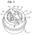
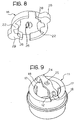
- FIG. 7 A second embodiment of a device according to the present invention is shown in Figures 7 to 9, in which parts and elements identical or corresponding to those in the preceding figures have been given the same reference numbers.
- the body 11 of the device is provided at its top with a bridge portion 24 which extends between the two diametrically opposite radial projections 18 of the body 11 and acts as a support for the cover 14.
- This portion 24 has a central hole 25 for a clip member for the cover 14, constituted by a pair of substantially semi-conical snap engagement teeth 26 which project downwardly from the centre of the cover.
- the portion 24 has a pair of semi-cylindrical notches 27 at its diametrically opposite ends for receiving corresponding semi-cylindrical radial projections 28 formed by the cover 14 in order to ensure that the cover is correctly centred on the body of the device.
- the bush 13 in order to allow the radial protuberance 15a on the bush 13 to disengage from the projections 17 on the body 11, the bush 13 forms at its top a pair of cam portions 21, substantially similar to those described above, designed to cooperate with a pair of retaining members 22 on the cover 14, like those of Figure 6, which extend radially inwardly and are offset angularly with respect to the centering projections 28.
- this latter is also provided with a pair of grip members 29 in the shape of handles projecting radially outwardly and aligned with the centering projections 28.
- this second embodiment of the device is similar to that of the first embodiment described above. The only difference is that now the cover 14 is secured to the body 11 by virtue of the engagement of the snap-engagement teeth 26 on the cover in the hole 25 in the bridge portion 24 of the body. In this case as well, anyway, the means for securing the two components (cover and body) define the axis of rotation of the cover relative to the body.
Landscapes
- Engineering & Computer Science (AREA)
- General Engineering & Computer Science (AREA)
- Health & Medical Sciences (AREA)
- Oral & Maxillofacial Surgery (AREA)
- Mechanical Engineering (AREA)
- Flexible Shafts (AREA)
- Mechanical Control Devices (AREA)
- Gear-Shifting Mechanisms (AREA)
- Clamps And Clips (AREA)
- Electric Cable Installation (AREA)
- Snaps, Bayonet Connections, Set Pins, And Snap Rings (AREA)
Claims (8)
- Dispositif de raccordement pour raccorder une extrémité d'un câble de commande à un élément de commande, en particulier un levier de vitesses d'une boîte de vitesses d'un véhicule à moteur; le dispositif comprenant
un corps externe (11) pouvant être raccordé au câble de commande et ayant une ouverture débouchante (12) ;
une douille (13) pouvant être insérée dans l'ouverture débouchante (12) dans le corps (11) pour être bloquée de manière amovible dans une position d'assemblage ; et
un couvercle (14) pour fermer l'ouverture débouchante (12) sur le côté axialement opposé à celui à travers lequel la douille (13) peut être insérée ;
dans lequel la douille (13) est prévue avec des moyens de mise en prise élastiques (15, 15a) capables de coopérer avec des moyens de retenue (17) respectifs du corps (11) afin de bloquer de manière amovible la douille (13) dans la position d'assemblage ;
caractérisé en ce que
la douille (13) est également prévue avec des parties de came (21) formées d'un seul tenant avec les moyens de mise en prise élastiques (15, 15a) ;
le couvercle (14) est fixé sur le corps (11) pour la rotation autour d'un axe de rotation qui coïncide sensiblement avec l'axe de l'ouverture (12) ;
le couvercle (14) est prévu avec des moyens de retenue (22) agencé pour coopérer avec les parties de came (21) de la douille (13) de sorte que suite à la rotation du couvercle autour dudit axe de rotation, les moyens de retenue (22) provoquent la déflexion élastique des parties de came (21) ainsi que des moyens de mise en prise (15, 15a) de la douille (13), provoquant ainsi le dégagement de ces derniers des éléments de retenue (17) du corps (11) et permettant à la douille (13) d'être retirée du corps (11). - Dispositif selon la revendication 1, caractérisé en ce que le corps (11) et le couvercle (14) sont également prévus avec des moyens d'accrochage (19, 20 ; 24, 25, 26) respectifs pour fixer le couvercle (14) sur le corps (11) afin de permettre au couvercle (14) d'être entraîné en rotation autour dudit axe de rotation.
- Dispositif selon la revendication 2, caractérisé en ce que lesdits moyens d'accrochage pour fixer le couvercle (14) sur le corps (11) comprennent des encliquetages (19) s'étendant verticalement à partir de l'extrémité du corps (11) faisant face au couvercle (14) et un bord circonférentiel en relief (20) formé par le couvercle (14) et pouvant être mis en prise par pression par les encliquetages (19).
- Dispositif selon la revendication 2, caractérisé en ce que lesdits moyens d'accrochage pour fixer le couvercle (14) sur le corps (11) comprennent des dents d'arrêt (26) faisant saillie à partir du centre du couvercle (14) et une partie de pont (24) formée d'un seul tenant avec le corps (11) et s'étendant de manière diamétrale à partir de l'extrémité du corps (11) faisant face au couvercle (14), ladite partie de pont (24) ayant un trou central (25) dans lequel les dents d'arrêt (26) peuvent être mises en prise.
- Dispositif selon la revendication 1, du type dans lequel les moyens de mise en prise élastiques (15, 15a) de la douille (13) sont constitués par une pluralité de membres (15) élastiquement déformables formant des protubérances (15a) radiales vers l'extérieur, caractérisé en ce que lesdites parties de came (21) sur la douille (13) s'étendent vers le haut à partir d'une paire de membres (15) diamétralement opposés.
- Dispositif selon la revendication 5, caractérisé en ce que lesdits moyens de retenue (22) du couvercle (14) sont formés par un élément en forme de barre s'étendant de manière diamétrale et pouvant fonctionner pour agir simultanément avec ses deux extrémités sur une paire de parties de came (21).
- Dispositif selon la revendication 5, caractérisé en ce que lesdits éléments de retenue (22) du couvercle (14) sont formés par une paire d'éléments en forme de demi disque agencés sur des côtés diamétralement opposés afin d'agir simultanément sur une paire de parties de came (21).
- Dispositif selon l'une quelconque des revendications précédentes, caractérisé en ce que le couvercle (14) est prévu avec des moyens de préhension (23, 29) sur lesquels un opérateur peut agir afin de faire tourner le couvercle.
Applications Claiming Priority (2)
| Application Number | Priority Date | Filing Date | Title |
|---|---|---|---|
| ITTO20030496 | 2003-06-30 | ||
| IT000496A ITTO20030496A1 (it) | 2003-06-30 | 2003-06-30 | Dispositivo di collegamento per un'estremita' di un cavo di azionamento. |
Publications (2)
| Publication Number | Publication Date |
|---|---|
| EP1493933A1 EP1493933A1 (fr) | 2005-01-05 |
| EP1493933B1 true EP1493933B1 (fr) | 2006-04-05 |
Family
ID=33428323
Family Applications (1)
| Application Number | Title | Priority Date | Filing Date |
|---|---|---|---|
| EP04015120A Expired - Lifetime EP1493933B1 (fr) | 2003-06-30 | 2004-06-28 | Dispositif de connection pour l'extrémité d'un câble de commande |
Country Status (12)
| Country | Link |
|---|---|
| US (1) | US20040265051A1 (fr) |
| EP (1) | EP1493933B1 (fr) |
| CN (1) | CN100394043C (fr) |
| AR (1) | AR044936A1 (fr) |
| AT (1) | ATE322630T1 (fr) |
| BR (1) | BRPI0402228A (fr) |
| DE (1) | DE602004000592T2 (fr) |
| DK (1) | DK1493933T3 (fr) |
| ES (1) | ES2262069T3 (fr) |
| IT (1) | ITTO20030496A1 (fr) |
| MA (1) | MA27217A1 (fr) |
| PT (1) | PT1493933E (fr) |
Families Citing this family (5)
| Publication number | Priority date | Publication date | Assignee | Title |
|---|---|---|---|---|
| JP4393900B2 (ja) * | 2003-06-26 | 2010-01-06 | 株式会社リコー | 現像装置、画像形成装置、プロセスカートリッジ及び現像方法 |
| JP2006273054A (ja) * | 2005-03-28 | 2006-10-12 | Fuji Kiko Co Ltd | シフトレバー装置 |
| US8469405B2 (en) * | 2009-10-20 | 2013-06-25 | Dave Wheatley Enterprises, Inc. | Securing mechanism for a coupling device |
| CN106523516B (zh) * | 2016-11-14 | 2019-01-15 | 苏州三星电子电脑有限公司 | 自锁转轴与具有该自锁转轴的笔记本电脑 |
| CN110332223B (zh) * | 2019-08-12 | 2024-07-16 | 格力博(江苏)股份有限公司 | 连接装置及自动工作设备 |
Family Cites Families (6)
| Publication number | Priority date | Publication date | Assignee | Title |
|---|---|---|---|---|
| US4348348A (en) * | 1980-06-23 | 1982-09-07 | Teleflex Incorporated | Method for making a remote control assembly with vibration dampener |
| FR2775740B1 (fr) * | 1998-03-06 | 2000-05-05 | United Parts France Sa | Articulation a rotule, en particulier pour embout de cable ou pour tringlerie de commande |
| DE19813721A1 (de) * | 1998-03-27 | 1999-10-07 | Fico Cables Sa | Verbindungselement |
| DE19918911A1 (de) * | 1999-04-26 | 2000-11-09 | Fico Cables Sa | Verbindungselement |
| US6324938B1 (en) * | 2000-02-28 | 2001-12-04 | Shimano, Inc. | Locking bicycle cable connecting apparatus |
| DE10156987A1 (de) * | 2001-11-21 | 2003-06-05 | Fico Cables Sa | Verbindungselement |
-
2003
- 2003-06-30 IT IT000496A patent/ITTO20030496A1/it unknown
-
2004
- 2004-06-28 AR ARP040102265A patent/AR044936A1/es active IP Right Grant
- 2004-06-28 EP EP04015120A patent/EP1493933B1/fr not_active Expired - Lifetime
- 2004-06-28 BR BR0402228-9A patent/BRPI0402228A/pt not_active IP Right Cessation
- 2004-06-28 AT AT04015120T patent/ATE322630T1/de not_active IP Right Cessation
- 2004-06-28 ES ES04015120T patent/ES2262069T3/es not_active Expired - Lifetime
- 2004-06-28 DK DK04015120T patent/DK1493933T3/da active
- 2004-06-28 PT PT04015120T patent/PT1493933E/pt unknown
- 2004-06-28 DE DE602004000592T patent/DE602004000592T2/de not_active Expired - Fee Related
- 2004-06-30 CN CNB2004100617493A patent/CN100394043C/zh not_active Expired - Fee Related
- 2004-06-30 US US10/879,739 patent/US20040265051A1/en not_active Abandoned
- 2004-06-30 MA MA27758A patent/MA27217A1/fr unknown
Also Published As
| Publication number | Publication date |
|---|---|
| DE602004000592D1 (de) | 2006-05-18 |
| CN1576620A (zh) | 2005-02-09 |
| EP1493933A1 (fr) | 2005-01-05 |
| DE602004000592T2 (de) | 2007-04-05 |
| ES2262069T3 (es) | 2006-11-16 |
| ITTO20030496A1 (it) | 2005-01-01 |
| ATE322630T1 (de) | 2006-04-15 |
| BRPI0402228A (pt) | 2005-05-17 |
| CN100394043C (zh) | 2008-06-11 |
| AR044936A1 (es) | 2005-10-12 |
| HK1074069A1 (en) | 2005-10-28 |
| US20040265051A1 (en) | 2004-12-30 |
| MA27217A1 (fr) | 2005-02-01 |
| PT1493933E (pt) | 2006-08-31 |
| DK1493933T3 (da) | 2006-07-03 |
Similar Documents
| Publication | Publication Date | Title |
|---|---|---|
| US5094643A (en) | Connecting device for toy construction elements | |
| CN103732473B (zh) | 转向装置 | |
| EP3649306B1 (fr) | Verrou à combinaison et procédé d'ouverture d'un verrou à combinaison | |
| EP1479928B1 (fr) | Dispositif de liaison d'une extremité d'un câble de commande avec systeme permettant d'assurer un assemblage correct | |
| US5791805A (en) | Locking device for telescoping elements | |
| CN104871374B (zh) | 插入式连接器的锁扣机构 | |
| EP3220011B1 (fr) | Dispositif à cames, dispositif d'ajustement de position pour volant et procédé d'assemblage de dispositif d'ajustement de position pour volant | |
| MX2007005596A (es) | Pieza de fijacion para un acoplamiento rapido. | |
| CN101228045A (zh) | 车辆握柄 | |
| KR100296890B1 (ko) | 작동케이블용체결장치 | |
| EP1493933A1 (fr) | Dispositif de connection pour l'extrémité d'un câble de commande | |
| CN113227629B (zh) | 联接器 | |
| JP7542084B2 (ja) | 2つの管状の物体を接続するための装置 | |
| EP2570701B1 (fr) | Ensemble de bouton | |
| US20060123943A1 (en) | Gear knob | |
| HK1074069B (en) | A connection device for an end of a control cable | |
| US4496334A (en) | Guard for a drive shaft | |
| KR101664753B1 (ko) | 변속 노브 조립체 | |
| EP3209895A1 (fr) | Raccord à rotule | |
| CN108351665B (zh) | 用于车辆的控制踏板的安装组件 | |
| WO2019105669A1 (fr) | Connecteur de ligne | |
| US5052242A (en) | Control device for a derailleur-gear for a bicycle | |
| KR100417046B1 (ko) | 빼고 꽂기형 문용 로크핸들장치 | |
| KR101799287B1 (ko) | 차량용 케이블의 연결장치 | |
| US6528743B1 (en) | Timer knob |
Legal Events
| Date | Code | Title | Description |
|---|---|---|---|
| PUAI | Public reference made under article 153(3) epc to a published international application that has entered the european phase |
Free format text: ORIGINAL CODE: 0009012 |
|
| AK | Designated contracting states |
Kind code of ref document: A1 Designated state(s): AT BE BG CH CY CZ DE DK EE ES FI FR GB GR HU IE IT LI LU MC NL PL PT RO SE SI SK TR |
|
| AX | Request for extension of the european patent |
Extension state: AL HR LT LV MK |
|
| 17P | Request for examination filed |
Effective date: 20050623 |
|
| AKX | Designation fees paid |
Designated state(s): AT BE BG CH CY CZ DE DK EE ES FI FR GB GR HU IE IT LI LU MC NL PL PT RO SE SI SK TR |
|
| GRAP | Despatch of communication of intention to grant a patent |
Free format text: ORIGINAL CODE: EPIDOSNIGR1 |
|
| REG | Reference to a national code |
Ref country code: HK Ref legal event code: DE Ref document number: 1074069 Country of ref document: HK |
|
| GRAS | Grant fee paid |
Free format text: ORIGINAL CODE: EPIDOSNIGR3 |
|
| GRAA | (expected) grant |
Free format text: ORIGINAL CODE: 0009210 |
|
| AK | Designated contracting states |
Kind code of ref document: B1 Designated state(s): AT BE BG CH CY CZ DE DK EE ES FI FR GB GR HU IE IT LI LU MC NL PL PT RO SE SI SK TR |
|
| PG25 | Lapsed in a contracting state [announced via postgrant information from national office to epo] |
Ref country code: PL Free format text: LAPSE BECAUSE OF FAILURE TO SUBMIT A TRANSLATION OF THE DESCRIPTION OR TO PAY THE FEE WITHIN THE PRESCRIBED TIME-LIMIT Effective date: 20060405 Ref country code: LI Free format text: LAPSE BECAUSE OF FAILURE TO SUBMIT A TRANSLATION OF THE DESCRIPTION OR TO PAY THE FEE WITHIN THE PRESCRIBED TIME-LIMIT Effective date: 20060405 Ref country code: FI Free format text: LAPSE BECAUSE OF FAILURE TO SUBMIT A TRANSLATION OF THE DESCRIPTION OR TO PAY THE FEE WITHIN THE PRESCRIBED TIME-LIMIT Effective date: 20060405 Ref country code: SK Free format text: LAPSE BECAUSE OF FAILURE TO SUBMIT A TRANSLATION OF THE DESCRIPTION OR TO PAY THE FEE WITHIN THE PRESCRIBED TIME-LIMIT Effective date: 20060405 Ref country code: NL Free format text: LAPSE BECAUSE OF FAILURE TO SUBMIT A TRANSLATION OF THE DESCRIPTION OR TO PAY THE FEE WITHIN THE PRESCRIBED TIME-LIMIT Effective date: 20060405 Ref country code: SI Free format text: LAPSE BECAUSE OF FAILURE TO SUBMIT A TRANSLATION OF THE DESCRIPTION OR TO PAY THE FEE WITHIN THE PRESCRIBED TIME-LIMIT Effective date: 20060405 Ref country code: RO Free format text: LAPSE BECAUSE OF FAILURE TO SUBMIT A TRANSLATION OF THE DESCRIPTION OR TO PAY THE FEE WITHIN THE PRESCRIBED TIME-LIMIT Effective date: 20060405 Ref country code: CH Free format text: LAPSE BECAUSE OF FAILURE TO SUBMIT A TRANSLATION OF THE DESCRIPTION OR TO PAY THE FEE WITHIN THE PRESCRIBED TIME-LIMIT Effective date: 20060405 Ref country code: AT Free format text: LAPSE BECAUSE OF FAILURE TO SUBMIT A TRANSLATION OF THE DESCRIPTION OR TO PAY THE FEE WITHIN THE PRESCRIBED TIME-LIMIT Effective date: 20060405 Ref country code: CZ Free format text: LAPSE BECAUSE OF FAILURE TO SUBMIT A TRANSLATION OF THE DESCRIPTION OR TO PAY THE FEE WITHIN THE PRESCRIBED TIME-LIMIT Effective date: 20060405 Ref country code: BE Free format text: LAPSE BECAUSE OF FAILURE TO SUBMIT A TRANSLATION OF THE DESCRIPTION OR TO PAY THE FEE WITHIN THE PRESCRIBED TIME-LIMIT Effective date: 20060405 Ref country code: IT Free format text: LAPSE BECAUSE OF FAILURE TO SUBMIT A TRANSLATION OF THE DESCRIPTION OR TO PAY THE FEE WITHIN THE PRESCRIBED TIME-LIMIT;WARNING: LAPSES OF ITALIAN PATENTS WITH EFFECTIVE DATE BEFORE 2007 MAY HAVE OCCURRED AT ANY TIME BEFORE 2007. THE CORRECT EFFECTIVE DATE MAY BE DIFFERENT FROM THE ONE RECORDED. Effective date: 20060405 |
|
| REG | Reference to a national code |
Ref country code: GB Ref legal event code: FG4D |
|
| REG | Reference to a national code |
Ref country code: CH Ref legal event code: EP |
|
| REG | Reference to a national code |
Ref country code: IE Ref legal event code: FG4D |
|
| REF | Corresponds to: |
Ref document number: 602004000592 Country of ref document: DE Date of ref document: 20060518 Kind code of ref document: P |
|
| PG25 | Lapsed in a contracting state [announced via postgrant information from national office to epo] |
Ref country code: IE Free format text: LAPSE BECAUSE OF NON-PAYMENT OF DUE FEES Effective date: 20060628 |
|
| PG25 | Lapsed in a contracting state [announced via postgrant information from national office to epo] |
Ref country code: MC Free format text: LAPSE BECAUSE OF NON-PAYMENT OF DUE FEES Effective date: 20060630 |
|
| REG | Reference to a national code |
Ref country code: DK Ref legal event code: T3 |
|
| REG | Reference to a national code |
Ref country code: SE Ref legal event code: TRGR |
|
| REG | Reference to a national code |
Ref country code: HK Ref legal event code: GR Ref document number: 1074069 Country of ref document: HK |
|
| REG | Reference to a national code |
Ref country code: PT Ref legal event code: SC4A Effective date: 20060616 |
|
| NLV1 | Nl: lapsed or annulled due to failure to fulfill the requirements of art. 29p and 29m of the patents act | ||
| REG | Reference to a national code |
Ref country code: CH Ref legal event code: PL |
|
| REG | Reference to a national code |
Ref country code: ES Ref legal event code: FG2A Ref document number: 2262069 Country of ref document: ES Kind code of ref document: T3 |
|
| ET | Fr: translation filed | ||
| PLBE | No opposition filed within time limit |
Free format text: ORIGINAL CODE: 0009261 |
|
| STAA | Information on the status of an ep patent application or granted ep patent |
Free format text: STATUS: NO OPPOSITION FILED WITHIN TIME LIMIT |
|
| 26N | No opposition filed |
Effective date: 20070108 |
|
| PG25 | Lapsed in a contracting state [announced via postgrant information from national office to epo] |
Ref country code: GR Free format text: LAPSE BECAUSE OF FAILURE TO SUBMIT A TRANSLATION OF THE DESCRIPTION OR TO PAY THE FEE WITHIN THE PRESCRIBED TIME-LIMIT Effective date: 20060706 |
|
| PG25 | Lapsed in a contracting state [announced via postgrant information from national office to epo] |
Ref country code: EE Free format text: LAPSE BECAUSE OF FAILURE TO SUBMIT A TRANSLATION OF THE DESCRIPTION OR TO PAY THE FEE WITHIN THE PRESCRIBED TIME-LIMIT Effective date: 20060405 Ref country code: BG Free format text: LAPSE BECAUSE OF FAILURE TO SUBMIT A TRANSLATION OF THE DESCRIPTION OR TO PAY THE FEE WITHIN THE PRESCRIBED TIME-LIMIT Effective date: 20060705 |
|
| PG25 | Lapsed in a contracting state [announced via postgrant information from national office to epo] |
Ref country code: HU Free format text: LAPSE BECAUSE OF FAILURE TO SUBMIT A TRANSLATION OF THE DESCRIPTION OR TO PAY THE FEE WITHIN THE PRESCRIBED TIME-LIMIT Effective date: 20061006 Ref country code: LU Free format text: LAPSE BECAUSE OF NON-PAYMENT OF DUE FEES Effective date: 20060628 |
|
| PGFP | Annual fee paid to national office [announced via postgrant information from national office to epo] |
Ref country code: DK Payment date: 20080513 Year of fee payment: 5 Ref country code: ES Payment date: 20080508 Year of fee payment: 5 |
|
| PGFP | Annual fee paid to national office [announced via postgrant information from national office to epo] |
Ref country code: TR Payment date: 20080521 Year of fee payment: 5 Ref country code: PT Payment date: 20080519 Year of fee payment: 5 |
|
| PGFP | Annual fee paid to national office [announced via postgrant information from national office to epo] |
Ref country code: DE Payment date: 20080523 Year of fee payment: 5 Ref country code: SE Payment date: 20080611 Year of fee payment: 5 |
|
| PG25 | Lapsed in a contracting state [announced via postgrant information from national office to epo] |
Ref country code: CY Free format text: LAPSE BECAUSE OF FAILURE TO SUBMIT A TRANSLATION OF THE DESCRIPTION OR TO PAY THE FEE WITHIN THE PRESCRIBED TIME-LIMIT Effective date: 20060405 |
|
| PGFP | Annual fee paid to national office [announced via postgrant information from national office to epo] |
Ref country code: FR Payment date: 20080630 Year of fee payment: 5 |
|
| PGFP | Annual fee paid to national office [announced via postgrant information from national office to epo] |
Ref country code: GB Payment date: 20080521 Year of fee payment: 5 |
|
| REG | Reference to a national code |
Ref country code: PT Ref legal event code: MM4A Free format text: LAPSE DUE TO NON-PAYMENT OF FEES Effective date: 20091228 |
|
| REG | Reference to a national code |
Ref country code: DK Ref legal event code: EBP |
|
| GBPC | Gb: european patent ceased through non-payment of renewal fee |
Effective date: 20090628 |
|
| REG | Reference to a national code |
Ref country code: FR Ref legal event code: ST Effective date: 20100226 |
|
| PG25 | Lapsed in a contracting state [announced via postgrant information from national office to epo] |
Ref country code: PT Free format text: LAPSE BECAUSE OF NON-PAYMENT OF DUE FEES Effective date: 20091228 |
|
| PG25 | Lapsed in a contracting state [announced via postgrant information from national office to epo] |
Ref country code: FR Free format text: LAPSE BECAUSE OF NON-PAYMENT OF DUE FEES Effective date: 20090630 |
|
| PG25 | Lapsed in a contracting state [announced via postgrant information from national office to epo] |
Ref country code: GB Free format text: LAPSE BECAUSE OF NON-PAYMENT OF DUE FEES Effective date: 20090628 |
|
| PG25 | Lapsed in a contracting state [announced via postgrant information from national office to epo] |
Ref country code: DE Free format text: LAPSE BECAUSE OF NON-PAYMENT OF DUE FEES Effective date: 20100101 |
|
| PG25 | Lapsed in a contracting state [announced via postgrant information from national office to epo] |
Ref country code: DK Free format text: LAPSE BECAUSE OF NON-PAYMENT OF DUE FEES Effective date: 20090630 |
|
| REG | Reference to a national code |
Ref country code: ES Ref legal event code: FD2A Effective date: 20090629 |
|
| PG25 | Lapsed in a contracting state [announced via postgrant information from national office to epo] |
Ref country code: ES Free format text: LAPSE BECAUSE OF NON-PAYMENT OF DUE FEES Effective date: 20090629 |
|
| PG25 | Lapsed in a contracting state [announced via postgrant information from national office to epo] |
Ref country code: SE Free format text: LAPSE BECAUSE OF NON-PAYMENT OF DUE FEES Effective date: 20090629 |
|
| PG25 | Lapsed in a contracting state [announced via postgrant information from national office to epo] |
Ref country code: TR Free format text: LAPSE BECAUSE OF NON-PAYMENT OF DUE FEES Effective date: 20090628 |