EP1493971B1 - Procédé pour le montage de turbines à gaz - Google Patents
Procédé pour le montage de turbines à gaz Download PDFInfo
- Publication number
- EP1493971B1 EP1493971B1 EP04252522.0A EP04252522A EP1493971B1 EP 1493971 B1 EP1493971 B1 EP 1493971B1 EP 04252522 A EP04252522 A EP 04252522A EP 1493971 B1 EP1493971 B1 EP 1493971B1
- Authority
- EP
- European Patent Office
- Prior art keywords
- combustor
- fuel injector
- fuel
- coupling
- air
- Prior art date
- Legal status (The legal status is an assumption and is not a legal conclusion. Google has not performed a legal analysis and makes no representation as to the accuracy of the status listed.)
- Expired - Lifetime
Links
- 238000000034 method Methods 0.000 title claims description 9
- 239000000446 fuel Substances 0.000 claims description 134
- 238000001816 cooling Methods 0.000 claims description 19
- 230000008878 coupling Effects 0.000 claims description 13
- 238000010168 coupling process Methods 0.000 claims description 13
- 238000005859 coupling reaction Methods 0.000 claims description 13
- 239000010763 heavy fuel oil Substances 0.000 claims description 4
- 238000010926 purge Methods 0.000 claims description 4
- 238000002485 combustion reaction Methods 0.000 description 19
- 239000007789 gas Substances 0.000 description 15
- 238000002347 injection Methods 0.000 description 14
- 239000007924 injection Substances 0.000 description 14
- 238000000889 atomisation Methods 0.000 description 4
- 239000007921 spray Substances 0.000 description 4
- 238000011144 upstream manufacturing Methods 0.000 description 4
- 238000004939 coking Methods 0.000 description 3
- 238000004891 communication Methods 0.000 description 3
- 230000005465 channeling Effects 0.000 description 2
- 239000000567 combustion gas Substances 0.000 description 2
- 238000007599 discharging Methods 0.000 description 2
- 239000012530 fluid Substances 0.000 description 2
- 238000003780 insertion Methods 0.000 description 2
- 230000037431 insertion Effects 0.000 description 2
- 238000007789 sealing Methods 0.000 description 2
- 230000005540 biological transmission Effects 0.000 description 1
- 230000002708 enhancing effect Effects 0.000 description 1
- 239000000284 extract Substances 0.000 description 1
- 238000009413 insulation Methods 0.000 description 1
- 239000000314 lubricant Substances 0.000 description 1
- 239000000203 mixture Substances 0.000 description 1
- 238000013021 overheating Methods 0.000 description 1
- 238000012546 transfer Methods 0.000 description 1
Images
Classifications
-
- F—MECHANICAL ENGINEERING; LIGHTING; HEATING; WEAPONS; BLASTING
- F23—COMBUSTION APPARATUS; COMBUSTION PROCESSES
- F23R—GENERATING COMBUSTION PRODUCTS OF HIGH PRESSURE OR HIGH VELOCITY, e.g. GAS-TURBINE COMBUSTION CHAMBERS
- F23R3/00—Continuous combustion chambers using liquid or gaseous fuel
- F23R3/42—Continuous combustion chambers using liquid or gaseous fuel characterised by the arrangement or form of the flame tubes or combustion chambers
- F23R3/60—Support structures; Attaching or mounting means
-
- F—MECHANICAL ENGINEERING; LIGHTING; HEATING; WEAPONS; BLASTING
- F23—COMBUSTION APPARATUS; COMBUSTION PROCESSES
- F23R—GENERATING COMBUSTION PRODUCTS OF HIGH PRESSURE OR HIGH VELOCITY, e.g. GAS-TURBINE COMBUSTION CHAMBERS
- F23R3/00—Continuous combustion chambers using liquid or gaseous fuel
- F23R3/28—Continuous combustion chambers using liquid or gaseous fuel characterised by the fuel supply
- F23R3/283—Attaching or cooling of fuel injecting means including supports for fuel injectors, stems, or lances
Definitions
- At least some known casings and components are supported by a plurality of support rings that are coupled together to form a backbone frame.
- the backbone frame provides structural support for components that are positioned radially inwardly from the backbone and also provides a means for an engine casing to be coupled around the engine.
- the backbone frame facilitates controlling engine clearance closures defined between the engine casing and components positioned radially inwardly from the backbone frame, such backbone frames are typically designed to be as stiff as possible.
- At least some known backbone frames used with recuperated engines include a plurality of beams that extend between forward and aft flanges.
- fuel injectors used with such engines require cooling. Accordingly, at least some known fuel injectors are cooled by fuel flowing through the fuel injector, as well as through the use of passive "dead air" insulation areas defined internally within the fuel injector. Moreover, to facilitate efficient operation of the fuel injectors, at least some known fuel injectors are designed to enable residual fuel to be forced out of the fuel injector and into an overboard drain during pre-determined combustor operations. In addition, an overall size of the fuel injectors is limited by combustor space limitations. Accordingly, designing an efficient fuel injector for use with such engines may be difficult.
- a combustion system for a gas turbine engine comprises a combustor, a combustor casing, and a fuel injector.
- the combustor includes a dome assembly and a combustor liner that extends downstream from the dome assembly.
- the combustor liner defines a combustion chamber therein.
- the combustor also includes a centerline axis.
- the combustor casing extends around the combustor.
- the fuel injector extends through the combustor casing and the dome assembly, and includes a fuel inlet, an injection tip, and a body extending between the fuel inlet and the injection tip.
- the injection tip is for discharging fuel into the combustor.
- the body includes at least one air inlet and at least one air outlet.
- the inlet is for receiving cooling air within the body.
- the outlet is for discharging cooling air external to the combustor case.
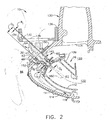
- FIG 2 is a cross-sectional illustration of a portion of gas turbine engine 10 including a fuel injector 30.
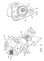
- Figure 3 is an enlarged perspective view of fuel injector 30 viewed from an upstream side 32 of fuel injector 30.
- Figure 4 is a plan view of fuel injector shown in Figure 3 and viewed from a downstream side 34 of fuel injector 30.
- fuel injector 30 includes a fuel inlet 42, an injection tip 44, and a body 46 that extends therebetween. Fuel inlet 42 coupled to a fuel supply source for channeling fuel into fuel injector 30, as is described in more detail below.
- injector body 46 includes an annular shoulder 48 that extends radially outward from body 46.
- Shoulder 48 facilitates positioning fuel injector 30 in proper orientation and alignment with respect to combustor 16 when fuel injector 30 is coupled within engine 10, as described in more detail below.
- injector shoulder 48 includes a plurality of openings 50 extending therethrough. Openings 50 are each sized to receive a fastener 52 therethrough (not shown) used to couple fuel injector 30 to combustor 16.
- injector 30 includes three openings 50 that are sized identically, and are each positioned adjacent an outer perimeter 54 of fuel injector shoulder 48.
- Shoulder 48 is substantially planar and separates fuel injection body 46 into an internal portion 60 that is extended into combustor 16, and is thus exposed to a combustion primary zone or combustion chamber 62 defined within combustor 16, and an external portion 64 that extends externally from combustor 16. More specifically, when fuel injector 30 is coupled to combustor 16, shoulder 48 prevents fuel injector external portion 64 from entering combustor 16. Accordingly, a length L of internal portion 60 is variably selected to facilitate limiting the depth of insertion of injector 30 and thus limits the amount of injector 30 exposed to radiant heat generated within combustion primary zone 62. More specifically, the combination of internal portion length L and relative position of shoulder 48 with respect to injector body 46 facilitates orienting fuel injection tip 44 in position within combustor 16.
- Fuel inlet 42 extends outwardly from fuel injector external portion 64. More specifically, inlet 42 is obliquely oriented with respect to a centerline axis 78 extending through injection tip 44 and body 46. In the exemplary embodiment, fuel inlet 42 is threaded to facilitate coupling inlet 42 to a fuel source.
- fuel injector external portion 64 also includes an air inlet 80 and at least one air vent 82.
- fuel injector external portion 64 includes at least one cooling cavity (not shown) defined therein. Fuel entering fuel inlet 42 is channeled through a passageway 83 extending from fuel inlet 42 through the cooling cavity to fuel injector internal portion 60.
- Air inlet 80 and each air vent 82 are coupled in flow communication with an air source for receiving cooling air therethrough. More specifically, in the exemplary embodiment, inlet 80 and vent 82 receive unrecuperated air therethrough. In one embodiment, inlet 80 and 82 receive unrecuperated intercompressor air which is at an operating temperature that is much less than an operating temperature of recuperated air. Cooling air entering air inlet 80 is oriented obliquely with respect to centerline axis 78 and is channeled through each cooling cavity, and around the fuel passageway before being discharged from fuel injector 30 through vents 82. As described in more detail below, spent cooling air discharged from vents 82 is discharged into the engine bay 86 rather than being discharged into combustor 16. In addition, the cooling air entering air inlet 80 also facilitates preventing overheating of fuel injector 30 and fuel coking within fuel injector 30.
- a shroud 90 circumscribes a portion of fuel injector internal portion 60 to facilitate shielding injection tip 44 and a portion of internal portion 60 from heat generated within combustion primary zone 62.
- shroud 90 is substantially circular.
- shroud 90 has a length L 2 that is shorter than fuel injector internal portion length L, and a diameter D 1 that is larger than a diameter (not shown) of fuel injector internal portion 60.
- Tip 44 includes a plurality of cooling openings 100 that extend through tip 44 and are in flow communication with injection tip 44 and air supplied to combustor 16 to facilitate atomization and spray control of fuel discharged from fuel injector 30.
- the air supplied to combustor 16 to facilitate atomization and spray control is recuperated, high pressure air that has been circulated through a recuperation cycle which adds exhaust gas heat into compressor discharge air.
- tip 44 is substantially circular, and openings 100 are circumferentially-spaced around tip 44.
- Combustor 16 includes an outer support 109, an annular outer liner 110, an inner support 111, an annular inner liner 112, and a domed end 113 that extends between outer and inner liners 110 and 112, respectively.
- Outer liner 110 and inner liner 112 are spaced radially inward from a combustor casing 114 and define combustion chamber 62.
- Combustor casing 114 is generally annular and extends around combustor 16 and inner and outer supports, 109 and 111 respectively.
- Combustion chamber 62 is generally annular in shape and is radially inward from liners 110 and 112.
- Outer support 111 and combustor casing 114 define an outer passageway 118 and inner support 109 and combustor casing 114 define an inner passageway 120.
- Outer and inner liners 110 and 112 extend to a turbine nozzle 122.
- a portion of combustor casing 114 also forms an opening 140 that provides a coupling seat for fuel injector 30.
- opening 140 has an inner diameter D 5 that is smaller than a width W of fuel injector shoulder 48, and is slightly larger than shroud diameter D 1 .
- shroud diameter D 1 is variably selected to allow enough space to enable a seal member 150 to be assembled, while facilitating reducing a radial distance R 1 between shroud 90 and an inner surface 152 defining casing opening 140. Reducing radial distance R 1 facilitates enhancing the effectiveness of seal member 150 to prevent recuperated air from escaping from combustor casing 114 past fuel injector 30.
- fuel injector shoulder 48 contacts casing 114 and limits an insertion depth of fuel injector internal portion 60 with respect to combustor 16. More specifically, shoulder 48 facilitates positioning fuel injection tip 44 in proper orientation and alignment with respect to combustor 16 when fuel injector 30 is coupled to combustor 16.
- fuel injector internal portion 60 is inserted through seal member 150 such that seal member 150 is deformed in sealing contact against shoulder 48.
- Fuel injector 30 is then inserted through casing opening 140 and is coupled in position with respect to combustor 16 using fasteners 52, such that seal member 150 is deformed in sealing contact between shoulder 48 and casing 114.
- a lubricant such as Tiolube 614-19B, commercially available from TIODIZE®, Huntington Beach, California.
- fuel and air are supplied to fuel injector 30. More specifically, fuel is supplied to fuel inlet 42, and unrecuperated cooling air is supplied to air inlet 80. The cooling air is circulated through injector body 46 prior to being discharged into engine bay 86. The combination of fuel and cooling air flowing through fuel injector 30 facilitates reducing an operating temperature of fuel injector 30.
- Fuel discharged from fuel injector 30 is discharged with approximately a ninety-degree spray cone with respect to domed end 113 and along a centerline axis 160 extending from domed end 113 through combustor 16. More specifically, as the fuel is discharged, the fuel is mixed with recuperated air supplied to combustor 16 to facilitate atomization and spray control of fuel discharged from injector 30. Moreover, the direction of fuel injection facilitates reducing a time for fuel ignition within combustion chamber 62. Accordingly, fuel discharged from fuel injector 30 is discharged into combustion chamber 62 in a direction that is substantially parallel to centerline axis 160.
- fuel flow to fuel injectors 30 is stopped, which makes fuel injectors 30 susceptible to coking.
- injectors 30 are purged with unrecuperated air supplied at a high pressure such that residual fuel is expelled into combustor 16.
- the operating temperature of the purge air is lower than an operating temperature of the recuperated air supplied to combustor 16 for fuel atomization.
- the purge air also facilitates reducing an operating temperature of fuel injector 30 and injection tip 44 during engine operations when fuel injector 30 is not employed.
- the above-described combustion support provides a cost-effective and reliable means for supplying fuel to a combustor with a fuel injector.
- the fuel injector includes a fuel inlet that enables fuel to be discharged into the combustion chamber in a direction that is substantially parallel to the combustor centerline axis, and an air inlet that enables unrecuperated air to flow through the fuel injector to facilitate cooling the fuel injector. Spent internal cooling air is then discharged into the engine bay.
- the fuel injector also includes a shroud that facilitates shielding the fuel injector from high temperatures generated within the combustor. Accordingly, a fuel injector is provided which enables fuel to be supplied to a combustor in a cost-effective and reliable manner.
- combustion system components illustrated are not limited to the specific embodiments described herein, but rather, components of each combustion system may be utilized independently and separately from other components described herein.
- each fuel injector may also be used in combination with other engine combustion systems.
Landscapes
- Engineering & Computer Science (AREA)
- Chemical & Material Sciences (AREA)
- Combustion & Propulsion (AREA)
- Mechanical Engineering (AREA)
- General Engineering & Computer Science (AREA)
- Fuel-Injection Apparatus (AREA)
- Turbine Rotor Nozzle Sealing (AREA)
Claims (5)
- Procédé d'assemblage d'un moteur à turbine à gaz (10), ledit procédé comprenant les étapes consistant à :coupler une chambre de combustion (16) comprenant un assemblage de dôme (113) et une chemise de chambre de combustion (110, 112) qui s'étend en aval de l'ensemble de dôme à un carter de chambre de combustion (114) qui est positionné radialement vers l'extérieur de la chambre de combustion ;coupler un injecteur de carburant (30) comprenant une entrée de carburant (42) et une entrée d'air (80) avec le carter de la chambre de combustion de sorte que l'injecteur de carburant s'étende axialement à travers l'ensemble de dôme afin que du carburant puisse être déchargé de l'injecteur de carburant (30) dans la chambre de combustion ; etcoupler l'entrée d'air à une source d'air de sorte que
l'air de refroidissement reçu à travers celle-ci soit mis en circulation à travers l'injecteur de carburant pour faciliter le refroidissement de l'injecteur de carburant, dans lequel le couplage de l'entrée d'air avec une source d'air comprend en outre le couplage de l'entrée d'air avec une source d'air en sorte que l'air de refroidissement consommé soit déchargé de l'injecteur de carburant à l'extérieur du carter de la chambre de combustion. - Procédé selon la revendication 1, comprenant en outre le couplage d'un support de couronne annulaire (132) qui comprend une première semelle radiale (134), une seconde semelle radiale (136) et une pluralité de poutres (138) qui s'étendent entre elles jusqu'au carter de la chambre de combustion de manière que l'injecteur de carburant soit positionné radialement vers l'intérieur du support de couronne.
- Procédé selon la revendication 1, dans lequel le couplage d'un injecteur de carburant comprenant une entrée de carburant et une entrée d'air avec le carter de la chambre de combustion comprend en outre le couplage de l'injecteur de carburant avec le carter de la chambre de combustion de sorte que du carburant soit déchargé de l'injecteur de carburant dans la chambre de combustion dans une direction sensiblement parallèle à un axe central s'étendant à travers la chambre de combustion.
- Procédé selon la revendication 1, comprenant en outre le couplage de la source de carburant de l'injecteur de carburant avec une source d'air pour faciliter la purge du carburant résiduaire de l'injecteur de carburant dans la chambre de combustion au cours d'opérations prédéterminées de la chambre de combustion.
- Procédé selon la revendication 1, dans lequel le couplage d'un injecteur de carburant comprenant une entrée de carburant et une entrée d'air avec le carter de la chambre de combustion comprend en outre le couplage de l'injecteur de carburant avec le carter de la chambre de combustion de sorte qu'un épaulement annulaire (48) s'étendant de l'injecteur de carburant oriente l'injecteur de carburant par rapport à la chambre de combustion.
Applications Claiming Priority (2)
| Application Number | Priority Date | Filing Date | Title |
|---|---|---|---|
| US613581 | 2003-07-02 | ||
| US10/613,581 US6955038B2 (en) | 2003-07-02 | 2003-07-02 | Methods and apparatus for operating gas turbine engine combustors |
Publications (3)
| Publication Number | Publication Date |
|---|---|
| EP1493971A2 EP1493971A2 (fr) | 2005-01-05 |
| EP1493971A3 EP1493971A3 (fr) | 2012-08-29 |
| EP1493971B1 true EP1493971B1 (fr) | 2015-09-09 |
Family
ID=33435476
Family Applications (1)
| Application Number | Title | Priority Date | Filing Date |
|---|---|---|---|
| EP04252522.0A Expired - Lifetime EP1493971B1 (fr) | 2003-07-02 | 2004-04-30 | Procédé pour le montage de turbines à gaz |
Country Status (4)
| Country | Link |
|---|---|
| US (1) | US6955038B2 (fr) |
| EP (1) | EP1493971B1 (fr) |
| CN (1) | CN1576698B (fr) |
| CA (1) | CA2464847C (fr) |
Families Citing this family (18)
| Publication number | Priority date | Publication date | Assignee | Title |
|---|---|---|---|---|
| EP1423645B1 (fr) * | 2001-09-07 | 2008-10-08 | Alstom Technology Ltd | Ensemble amortisseur concu pour reduire les pulsations d'une chambre de combustion dans une installation de turbine a gaz |
| US7152411B2 (en) * | 2003-06-27 | 2006-12-26 | General Electric Company | Rabbet mounted combuster |
| US7093419B2 (en) * | 2003-07-02 | 2006-08-22 | General Electric Company | Methods and apparatus for operating gas turbine engine combustors |
| JP2005076982A (ja) * | 2003-08-29 | 2005-03-24 | Mitsubishi Heavy Ind Ltd | ガスタービン燃焼器 |
| US7310952B2 (en) * | 2003-10-17 | 2007-12-25 | General Electric Company | Methods and apparatus for attaching swirlers to gas turbine engine combustors |
| US7464554B2 (en) * | 2004-09-09 | 2008-12-16 | United Technologies Corporation | Gas turbine combustor heat shield panel or exhaust panel including a cooling device |
| US7493771B2 (en) * | 2005-11-30 | 2009-02-24 | General Electric Company | Methods and apparatuses for assembling a gas turbine engine |
| US20070277530A1 (en) * | 2006-05-31 | 2007-12-06 | Constantin Alexandru Dinu | Inlet flow conditioner for gas turbine engine fuel nozzle |
| US7874164B2 (en) * | 2006-11-03 | 2011-01-25 | Pratt & Whitney Canada Corp. | Fuel nozzle flange with reduced heat transfer |
| US8899051B2 (en) | 2010-12-30 | 2014-12-02 | Rolls-Royce Corporation | Gas turbine engine flange assembly including flow circuit |
| US20120304655A1 (en) * | 2011-06-01 | 2012-12-06 | General Electric Company | Turbomachine combustor assembly including a liner stop |
| US10378771B2 (en) * | 2016-02-25 | 2019-08-13 | General Electric Company | Combustor assembly |
| US20180356094A1 (en) * | 2017-06-09 | 2018-12-13 | General Electric Company | Variable geometry rotating detonation combustor |
| US10982593B2 (en) * | 2017-06-16 | 2021-04-20 | General Electric Company | System and method for combusting liquid fuel in a gas turbine combustor with staged combustion |
| US11280492B2 (en) | 2018-08-23 | 2022-03-22 | General Electric Company | Combustor assembly for a turbo machine |
| CN109296464B (zh) * | 2018-10-21 | 2023-10-20 | 靳普 | 喷嘴密封结构和微型燃气轮机发电机组 |
| US11846422B2 (en) * | 2021-08-19 | 2023-12-19 | Collins Engine Nozzles, Inc. | Systems for fuel injectors with fuel air heat exchangers |
| US11859819B2 (en) | 2021-10-15 | 2024-01-02 | General Electric Company | Ceramic composite combustor dome and liners |
Family Cites Families (17)
| Publication number | Priority date | Publication date | Assignee | Title |
|---|---|---|---|---|
| DE2710618C2 (de) * | 1977-03-11 | 1982-11-11 | MTU Motoren- und Turbinen-Union München GmbH, 8000 München | Brennstoffeinspritzdüse für Gasturbinentriebwerke |
| JPS5413020A (en) * | 1977-06-30 | 1979-01-31 | Nippon Oxygen Co Ltd | Liquid fuel burner |
| US4858538A (en) * | 1988-06-16 | 1989-08-22 | Shell Oil Company | Partial combustion burner |
| US4950129A (en) | 1989-02-21 | 1990-08-21 | General Electric Company | Variable inlet guide vanes for an axial flow compressor |
| US5281085A (en) | 1990-12-21 | 1994-01-25 | General Electric Company | Clearance control system for separately expanding or contracting individual portions of an annular shroud |
| US5228828A (en) | 1991-02-15 | 1993-07-20 | General Electric Company | Gas turbine engine clearance control apparatus |
| US5222360A (en) | 1991-10-30 | 1993-06-29 | General Electric Company | Apparatus for removably attaching a core frame to a vane frame with a stable mid ring |
| US5273396A (en) | 1992-06-22 | 1993-12-28 | General Electric Company | Arrangement for defining improved cooling airflow supply path through clearance control ring and shroud |
| US5820024A (en) | 1994-05-16 | 1998-10-13 | General Electric Company | Hollow nozzle actuating ring |
| US5911679A (en) | 1996-12-31 | 1999-06-15 | General Electric Company | Variable pitch rotor assembly for a gas turbine engine inlet |
| GB9708662D0 (en) * | 1997-04-30 | 1997-06-18 | Rolls Royce Plc | Fuel injector |
| US6045325A (en) | 1997-12-18 | 2000-04-04 | United Technologies Corporation | Apparatus for minimizing inlet airflow turbulence in a gas turbine engine |
| US6311471B1 (en) * | 1999-01-08 | 2001-11-06 | General Electric Company | Steam cooled fuel injector for gas turbine |
| US6438963B1 (en) * | 2000-08-31 | 2002-08-27 | General Electric Company | Liquid fuel and water injection purge systems and method for a gas turbine having a three-way purge valve |
| FR2817017B1 (fr) * | 2000-11-21 | 2003-03-07 | Snecma Moteurs | Refroidissement integral des injecteurs de decollage d'une chambre de combustion a deux tetes |
| US6606861B2 (en) * | 2001-02-26 | 2003-08-19 | United Technologies Corporation | Low emissions combustor for a gas turbine engine |
| US7827795B2 (en) * | 2008-09-19 | 2010-11-09 | Woodward Governor Company | Active thermal protection for fuel injectors |
-
2003
- 2003-07-02 US US10/613,581 patent/US6955038B2/en not_active Expired - Lifetime
-
2004
- 2004-04-22 CA CA2464847A patent/CA2464847C/fr not_active Expired - Fee Related
- 2004-04-30 EP EP04252522.0A patent/EP1493971B1/fr not_active Expired - Lifetime
- 2004-04-30 CN CN2004100422118A patent/CN1576698B/zh not_active Expired - Lifetime
Also Published As
| Publication number | Publication date |
|---|---|
| CN1576698B (zh) | 2010-09-01 |
| CN1576698A (zh) | 2005-02-09 |
| US6955038B2 (en) | 2005-10-18 |
| CA2464847A1 (fr) | 2005-01-02 |
| EP1493971A3 (fr) | 2012-08-29 |
| EP1493971A2 (fr) | 2005-01-05 |
| US20050000226A1 (en) | 2005-01-06 |
| CA2464847C (fr) | 2011-09-13 |
Similar Documents
| Publication | Publication Date | Title |
|---|---|---|
| EP1172611B1 (fr) | Chanbre de combustion de turbine à gaz avec joint entre le dome et la chemise | |
| CA2464847C (fr) | Appareil d'exploitation de chambres de combustion de turbine a gaz | |
| US7216488B2 (en) | Methods and apparatus for cooling turbine engine combustor ignition devices | |
| US7721437B2 (en) | Methods for assembling gas turbine engine combustors | |
| US7007482B2 (en) | Combustion liner seal with heat transfer augmentation | |
| US7051532B2 (en) | Methods and apparatus for film cooling gas turbine engine combustors | |
| EP1493970B1 (fr) | Procédés et appareil pour l'exploitation des chambres de combustion de turbines à gaz | |
| CN113864818A (zh) | 燃烧器空气流动路径 | |
| JP6001854B2 (ja) | タービンエンジン用燃焼器組立体及びその組み立て方法 | |
| US20140318139A1 (en) | Premixer assembly for gas turbine combustor | |
| US7360364B2 (en) | Method and apparatus for assembling gas turbine engine combustors | |
| GB2434858A (en) | Combustor Liner Support Arrangement |
Legal Events
| Date | Code | Title | Description |
|---|---|---|---|
| PUAI | Public reference made under article 153(3) epc to a published international application that has entered the european phase |
Free format text: ORIGINAL CODE: 0009012 |
|
| AK | Designated contracting states |
Kind code of ref document: A2 Designated state(s): AT BE BG CH CY CZ DE DK EE ES FI FR GB GR HU IE IT LI LU MC NL PL PT RO SE SI SK TR |
|
| AX | Request for extension of the european patent |
Extension state: AL HR LT LV MK |
|
| PUAL | Search report despatched |
Free format text: ORIGINAL CODE: 0009013 |
|
| AK | Designated contracting states |
Kind code of ref document: A3 Designated state(s): AT BE BG CH CY CZ DE DK EE ES FI FR GB GR HU IE IT LI LU MC NL PL PT RO SE SI SK TR |
|
| AX | Request for extension of the european patent |
Extension state: AL HR LT LV MK |
|
| RIC1 | Information provided on ipc code assigned before grant |
Ipc: F23R 3/28 20060101AFI20120723BHEP Ipc: F23R 3/60 20060101ALI20120723BHEP |
|
| 17P | Request for examination filed |
Effective date: 20130228 |
|
| AKX | Designation fees paid |
Designated state(s): DE FR GB IT SE |
|
| 17Q | First examination report despatched |
Effective date: 20130612 |
|
| GRAP | Despatch of communication of intention to grant a patent |
Free format text: ORIGINAL CODE: EPIDOSNIGR1 |
|
| INTG | Intention to grant announced |
Effective date: 20150327 |
|
| GRAS | Grant fee paid |
Free format text: ORIGINAL CODE: EPIDOSNIGR3 |
|
| GRAA | (expected) grant |
Free format text: ORIGINAL CODE: 0009210 |
|
| AK | Designated contracting states |
Kind code of ref document: B1 Designated state(s): DE FR GB IT SE |
|
| REG | Reference to a national code |
Ref country code: GB Ref legal event code: FG4D |
|
| REG | Reference to a national code |
Ref country code: DE Ref legal event code: R096 Ref document number: 602004047851 Country of ref document: DE |
|
| REG | Reference to a national code |
Ref country code: SE Ref legal event code: TRGR |
|
| REG | Reference to a national code |
Ref country code: FR Ref legal event code: PLFP Year of fee payment: 13 |
|
| REG | Reference to a national code |
Ref country code: DE Ref legal event code: R097 Ref document number: 602004047851 Country of ref document: DE |
|
| PLBE | No opposition filed within time limit |
Free format text: ORIGINAL CODE: 0009261 |
|
| STAA | Information on the status of an ep patent application or granted ep patent |
Free format text: STATUS: NO OPPOSITION FILED WITHIN TIME LIMIT |
|
| 26N | No opposition filed |
Effective date: 20160610 |
|
| REG | Reference to a national code |
Ref country code: FR Ref legal event code: PLFP Year of fee payment: 14 |
|
| PGFP | Annual fee paid to national office [announced via postgrant information from national office to epo] |
Ref country code: FR Payment date: 20170426 Year of fee payment: 14 Ref country code: GB Payment date: 20170427 Year of fee payment: 14 Ref country code: DE Payment date: 20170427 Year of fee payment: 14 |
|
| PGFP | Annual fee paid to national office [announced via postgrant information from national office to epo] |
Ref country code: IT Payment date: 20170421 Year of fee payment: 14 Ref country code: SE Payment date: 20170427 Year of fee payment: 14 |
|
| REG | Reference to a national code |
Ref country code: DE Ref legal event code: R119 Ref document number: 602004047851 Country of ref document: DE |
|
| GBPC | Gb: european patent ceased through non-payment of renewal fee |
Effective date: 20180430 |
|
| REG | Reference to a national code |
Ref country code: SE Ref legal event code: EUG |
|
| PG25 | Lapsed in a contracting state [announced via postgrant information from national office to epo] |
Ref country code: SE Free format text: LAPSE BECAUSE OF NON-PAYMENT OF DUE FEES Effective date: 20180501 Ref country code: DE Free format text: LAPSE BECAUSE OF NON-PAYMENT OF DUE FEES Effective date: 20181101 |
|
| PG25 | Lapsed in a contracting state [announced via postgrant information from national office to epo] |
Ref country code: GB Free format text: LAPSE BECAUSE OF NON-PAYMENT OF DUE FEES Effective date: 20180430 |
|
| PG25 | Lapsed in a contracting state [announced via postgrant information from national office to epo] |
Ref country code: IT Free format text: LAPSE BECAUSE OF NON-PAYMENT OF DUE FEES Effective date: 20180430 Ref country code: FR Free format text: LAPSE BECAUSE OF NON-PAYMENT OF DUE FEES Effective date: 20180430 |