EP1494096B1 - Zeitgebervorrichtung und verfahren zur steuerung der zeitgebervorrichtung - Google Patents
Zeitgebervorrichtung und verfahren zur steuerung der zeitgebervorrichtung Download PDFInfo
- Publication number
- EP1494096B1 EP1494096B1 EP04713171A EP04713171A EP1494096B1 EP 1494096 B1 EP1494096 B1 EP 1494096B1 EP 04713171 A EP04713171 A EP 04713171A EP 04713171 A EP04713171 A EP 04713171A EP 1494096 B1 EP1494096 B1 EP 1494096B1
- Authority
- EP
- European Patent Office
- Prior art keywords
- piezoelectric actuator
- time information
- timing device
- antenna
- oscillation
- Prior art date
- Legal status (The legal status is an assumption and is not a legal conclusion. Google has not performed a legal analysis and makes no representation as to the accuracy of the status listed.)
- Expired - Lifetime
Links
- 238000000034 method Methods 0.000 title claims description 13
- 230000010355 oscillation Effects 0.000 claims description 72
- 230000006854 communication Effects 0.000 claims description 14
- 238000004891 communication Methods 0.000 claims description 13
- 230000003014 reinforcing effect Effects 0.000 claims description 8
- 230000008602 contraction Effects 0.000 claims description 7
- 238000006073 displacement reaction Methods 0.000 claims description 4
- 230000010360 secondary oscillation Effects 0.000 description 30
- 238000010586 diagram Methods 0.000 description 17
- 230000004048 modification Effects 0.000 description 11
- 238000012986 modification Methods 0.000 description 11
- 230000007246 mechanism Effects 0.000 description 9
- 230000000694 effects Effects 0.000 description 7
- 239000013078 crystal Substances 0.000 description 6
- 230000005540 biological transmission Effects 0.000 description 5
- 238000012937 correction Methods 0.000 description 5
- 230000005674 electromagnetic induction Effects 0.000 description 5
- 238000010248 power generation Methods 0.000 description 5
- 230000005611 electricity Effects 0.000 description 4
- 230000003321 amplification Effects 0.000 description 3
- 230000008859 change Effects 0.000 description 3
- 230000007423 decrease Effects 0.000 description 3
- 238000001514 detection method Methods 0.000 description 3
- 238000003199 nucleic acid amplification method Methods 0.000 description 3
- 230000008569 process Effects 0.000 description 3
- 229910000859 α-Fe Inorganic materials 0.000 description 3
- XEEYBQQBJWHFJM-UHFFFAOYSA-N Iron Chemical compound [Fe] XEEYBQQBJWHFJM-UHFFFAOYSA-N 0.000 description 2
- 229910000831 Steel Inorganic materials 0.000 description 2
- 230000005484 gravity Effects 0.000 description 2
- 239000000463 material Substances 0.000 description 2
- 230000010287 polarization Effects 0.000 description 2
- 229910001220 stainless steel Inorganic materials 0.000 description 2
- 239000010935 stainless steel Substances 0.000 description 2
- 239000010959 steel Substances 0.000 description 2
- 210000000707 wrist Anatomy 0.000 description 2
- 241001481828 Glyptocephalus cynoglossus Species 0.000 description 1
- 239000002033 PVDF binder Substances 0.000 description 1
- 230000009471 action Effects 0.000 description 1
- 238000013459 approach Methods 0.000 description 1
- JRPBQTZRNDNNOP-UHFFFAOYSA-N barium titanate Chemical compound [Ba+2].[Ba+2].[O-][Ti]([O-])([O-])[O-] JRPBQTZRNDNNOP-UHFFFAOYSA-N 0.000 description 1
- 229910002113 barium titanate Inorganic materials 0.000 description 1
- NKZSPGSOXYXWQA-UHFFFAOYSA-N dioxido(oxo)titanium;lead(2+) Chemical compound [Pb+2].[O-][Ti]([O-])=O NKZSPGSOXYXWQA-UHFFFAOYSA-N 0.000 description 1
- 230000005284 excitation Effects 0.000 description 1
- 239000000284 extract Substances 0.000 description 1
- 210000004247 hand Anatomy 0.000 description 1
- 230000006872 improvement Effects 0.000 description 1
- 229910052742 iron Inorganic materials 0.000 description 1
- JQJCSZOEVBFDKO-UHFFFAOYSA-N lead zinc Chemical compound [Zn].[Pb] JQJCSZOEVBFDKO-UHFFFAOYSA-N 0.000 description 1
- HFGPZNIAWCZYJU-UHFFFAOYSA-N lead zirconate titanate Chemical compound [O-2].[O-2].[O-2].[O-2].[O-2].[Ti+4].[Zr+4].[Pb+2] HFGPZNIAWCZYJU-UHFFFAOYSA-N 0.000 description 1
- GQYHUHYESMUTHG-UHFFFAOYSA-N lithium niobate Chemical compound [Li+].[O-][Nb](=O)=O GQYHUHYESMUTHG-UHFFFAOYSA-N 0.000 description 1
- 230000005389 magnetism Effects 0.000 description 1
- 230000007257 malfunction Effects 0.000 description 1
- 238000005259 measurement Methods 0.000 description 1
- 229920002981 polyvinylidene fluoride Polymers 0.000 description 1
- 238000012545 processing Methods 0.000 description 1
- 239000010453 quartz Substances 0.000 description 1
- 230000009467 reduction Effects 0.000 description 1
- 230000029058 respiratory gaseous exchange Effects 0.000 description 1
- 229910052706 scandium Inorganic materials 0.000 description 1
- SIXSYDAISGFNSX-UHFFFAOYSA-N scandium atom Chemical compound [Sc] SIXSYDAISGFNSX-UHFFFAOYSA-N 0.000 description 1
- 238000007493 shaping process Methods 0.000 description 1
- VYPSYNLAJGMNEJ-UHFFFAOYSA-N silicon dioxide Inorganic materials O=[Si]=O VYPSYNLAJGMNEJ-UHFFFAOYSA-N 0.000 description 1
Images






Classifications
-
- G—PHYSICS
- G04—HOROLOGY
- G04C—ELECTROMECHANICAL CLOCKS OR WATCHES
- G04C3/00—Electromechanical clocks or watches independent of other time-pieces and in which the movement is maintained by electric means
- G04C3/08—Electromechanical clocks or watches independent of other time-pieces and in which the movement is maintained by electric means wherein movement is regulated by a mechanical oscillator other than a pendulum or balance, e.g. by a tuning fork, e.g. electrostatically
- G04C3/12—Electromechanical clocks or watches independent of other time-pieces and in which the movement is maintained by electric means wherein movement is regulated by a mechanical oscillator other than a pendulum or balance, e.g. by a tuning fork, e.g. electrostatically driven by piezoelectric means; driven by magneto-strictive means
-
- G—PHYSICS
- G04—HOROLOGY
- G04R—RADIO-CONTROLLED TIME-PIECES
- G04R60/00—Constructional details
- G04R60/06—Antennas attached to or integrated in clock or watch bodies
- G04R60/10—Antennas attached to or integrated in clock or watch bodies inside cases
-
- G—PHYSICS
- G04—HOROLOGY
- G04R—RADIO-CONTROLLED TIME-PIECES
- G04R60/00—Constructional details
- G04R60/14—Constructional details specific to electromechanical timepieces, e.g. moving parts thereof
Definitions
- the present invention relates to a drive device, a timing device, and a method for controlling a timing device, and particularly relates to a drive device, timing device, and method for controlling a timing device used for a radio-controlled timepiece or timepiece equipped with a generating device that utilizes electromagnetic induction.
- Timepieces with electromagnetic generators that are equipped with a power generator having a generating coil, and that generate electricity with electromagnetic induction and store the generated electrical power to be used as a driving power source, are currently being commercialized (for example, see Japanese Patent No. 2000-147167 ).
- the conventional timepieces with electromagnetic generators described above have a large leakage field when the electric motor generates electricity, the leakage field has no small effect on the electromagnetic motor for the timepiece, and it is possible that the timepiece may stop due to the leakage field and the displayed time will be slowed.
- JG2AS LF standard wave
- JG2AS LF standard wave
- This time data include the total number of days from the first day of the first month of the current year, the current hour, the current minutes, and other such data.
- Japanese Patent No. 3163403 employs a configuration in which a circuit is provided for stopping the stepping motor while the LF standard wave is received, the generation of electromagnetic noise originating in the driving of the stepping motor is prevented, and the current time is corrected after the LF standard wave is received.
- the radio-controlled timepiece described in Japanese Patent No. 3163403 has had drawbacks in that the circuit configuration is complicated and the time cannot be correctly displayed while the LF standard wave is received.
- JP 2002 214 367 A is concerned with a watch
- JP 2002 291 264 A is concerned with a piezoelectric actuator
- JP-A-8 037 785 is concerned with an ultrasonic motor.
- an object of the present invention is to provide a drive device, a timing device, and a method for controlling a timing device in which the circuit structure can be simplified and the time accurately displayed even during power generation or reception of LF standard waves.
- the timing device according to a first aspect of the present invention is defined in claim 1.
- the communication unit communicates with an external communication device via an antenna
- the time display unit uses a piezoelectric actuator as a drive source and displays time information with a mechanical structure conjunction therewith or independently therefrom.
- the first aspect is characterized in that the piezoelectric actuator rotatably drives the rotor by elliptical movement resulting from a combination of longitudinal oscillation and curved oscillation.
- the first aspect is characterized in that the piezoelectric actuator (*1) has an oscillating plate obtained by stacking a plate-shaped piezoelectric element and a reinforcing plate, a holding section for holding the oscillating plate on a support, and a contact section provided to the longitudinal tip of the oscillating plate; and a drive signal is supplied to the piezoelectric element, whereby the piezoelectric element is caused to expand and contract, oscillations of expansion and contraction in the longitudinal direction and oscillations in the direction that intersects the longitudinal direction are induced in the oscillating plate, and a rotor is rotatably driven by the displacement of the contact section that accompanies these oscillations.
- the first aspect is characterized in that the time display unit has a pointer driving actuator for driving pointers that display time information; and the antenna is disposed at a location in which the positive projection of the antenna on a plane perpendicular to the thickness direction of the timing device does not overlap the positive projection of the pointer driving piezoelectric actuator on the plane, and is also disposed to be separated by a specific distance in a direction perpendicular to the thickness direction.
- the first aspect is further characterized in that the time display unit has a pointer driving actuator for driving pointers that display time information; and the antenna is disposed at a location in which at least part of the positive projection of the antenna on a plane perpendicular to the thickness direction of the timing device overlaps the positive projection of the pointer driving piezoelectric actuator on the plane, and is also disposed to be separated by a specific distance in the thickness direction.
- the method for controlling a timing device according to a sixth aspect of the present invention is defined in claim 6.
- the first embodiment will first be described.
- FIG. 1 is a structural block diagram showing an analog electronic timepiece according to the present embodiment.
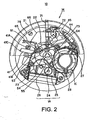
- FIG. 2 is a plan view showing the same analog electronic timepiece:
- the object of control for the drive device is a time display mechanism 5, and the time display mechanism 5 is operated by means of a piezoelectric actuator 41 constituting the drive device.
- An electric power source 1 has a generating coil and an oscillating weight to be hereinafter described, and includes a generator unit (generating means) 1A for generating electricity by converting the kinetic energy of the oscillating weight to electric energy by electromagnetic induction, a rectifying circuit 1B for rectifying the AC power generated by the generator unit 1A into DC power, and a secondary battery (storage means) 1C for storing the rectified DC power.
- a generator unit (generating means) 1A for generating electricity by converting the kinetic energy of the oscillating weight to electric energy by electromagnetic induction
- a rectifying circuit 1B for rectifying the AC power generated by the generator unit 1A into DC power
- secondary battery (storage means) 1C for storing the rectified DC power.
- the electric energy from the electric power source 1 is received and an oscillating circuit 201 of an electronic circuit 2 oscillates at a standard signal, which is 32,768 Hz.
- the standard signal of 32,768 Hz is converted to 1 Hz in a divider circuit 202.
- a signal from the divider circuit 202 is sent to a control circuit 225.
- This control circuit 225 controls the supply timing for the drive pulse of the piezoelectric actuator 41, which is the drive source for the time display mechanism 5.
- the control circuit 225 then inputs a drive pulse command signal to an oscillating circuit 2361, which sends the drive pulse to the piezoelectric actuator 41.
- the drive pulse command signal with controlled supply timing is inputted from the control circuit 225 to the oscillating circuit 2361, and is then inputted to an electric motor drive circuit 2363 via a waveform shaping circuit 2362.
- This electric motor drive circuit 2363 supplies a drive pulse to the piezoelectric actuator 41.
- the piezoelectric actuator 41 converts the electric energy into mechanical energy according to the drive pulse, and utilizes the piezoelectric effect to push the external periphery of the driven body (rotor) 51.
- the rotor 51 rotated by the pushing action of the piezoelectric actuator 41, rotatably drives a transmission mechanism (reduction gear train) 4 and the time display mechanism 5.
- the display on the time display mechanism 5 is corrected by means of a time correction device 8.
- FIG. 2 is a partial plan view of the timing device relating to the first embodiment.
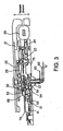
- FIG. 3 is a cross-sectional view of part of the timing device.
- the timing device 10 is a wristwatch designed for use by wrapping a belt coupled with the main body of the device around the wrist of the user.
- the timing device 10 includes an electric power source 1 (see FIG. 1 ), and also has a timing unit (drive means) and operating unit 14 to be hereinafter described.
- the electric power source 1 of the timing device 10 includes an oscillating weight 21, an oscillating weight wheel 22, a generating rotor intermediate wheel 23, a generating rotor 24, a generating stator 25, a generating coil 26, a secondary battery 1C, a secondary battery positive terminal 27 and secondary battery negative terminal 28 for electrically connecting the secondary battery 1C and a base plate, an oscillating weight support 29, and a bearing 30.
- the generating rotor 24, generating stator 25, and generating coil 26 constitute the generator unit 1A.
- the timing unit includes a piezoelectric actuator 41 for driving a second hand as a pointer component, a transmission mechanism (gear train section) 4 for transmitting the driving force for driving the pointer, a crystal oscillator 44 for keeping time, and a timing IC 45 for performing various timing processes on the basis of standard oscillation signals for timing.
- the transmission mechanism 4 is similar to a regular analog timepiece and includes a rotor 51, a rotor pinion 52, a fifth wheel and pinion 53, a fourth wheel and pinion 54, a third wheel and pinion 55, a second wheel and pinion 56, an hour wheel 57, a second hand 61, a minute hand 62, an hour hand (hour display means) 63, a minute wheel 64, a rotor press member 65, and a train wheel bridge 66.
- the operating unit 14 includes a setting stem 71, a setting lever 72, and a yoke 73, and is designed to be able to perform various settings, including time setting and time correction, similar to other timing devices.
- the setting stem 71, setting lever 72, and yoke 73 are made from steel materials in order to be more compact.
- the timing device 10 includes a main plate 75 and a circuit press plate 76 as structural components.
- the generator unit 1A is disposed at a location in which the positive projection of the generator on this plane does not overlap the positive projection of the piezoelectric actuator 41 on this plane.
- Such an arrangement allows the thickness of the timing device 10 to be reduced and makes it possible to configure a thin wristwatch with an electromagnetic generator.
- the piezoelectric actuator constituting the drive device will now be described.
- FIG. 4 is an explanatory diagram of the configuration of the piezoelectric actuator.
- the piezoelectric actuator 41 is configured with a stainless steel plate or another such reinforcing plate 115 held between two plate-shaped piezoelectric elements 113 and 114, as shown in FIG. 4 .
- a holding section 41A (see FIG. 2 ), a contact section 41B, and a balance section 41C are formed integrally on the reinforcing plate 115. This layered structure makes it possible to suppress the over-amplitude of the piezoelectric actuator 41 and the damage to the piezoelectric elements 113 and 114 by external forces.
- Electrodes 113A and 114A are arranged on top of the piezoelectric elements 113 and 114 as shown in FIG. 4 , and the voltage from a drive circuit 200 is supplied to the piezoelectric elements 113 and 114 via these electrodes 113A and 114A.
- the piezoelectric elements 113 and 114 are displaced so as to expand and contract if an alternating-current drive signal is supplied from the drive circuit 200, such that the electric potentials at the top, middle, and bottom in the diagram are +V, -V, and +V (or -V, +V, and -V), respectively.
- the +V drive signal and the -V drive signal are alternating-current signals whose phases have been reversed. Therefore, the amplitude of the oscillation created in the piezoelectric element 113 on top of the reinforcing plate 115 and the piezoelectric element 114 on the bottom can be increased compared to when 0 V is applied to the reinforcing plate 115 (when the reinforcing plate 115 is connected to the grounding wire of the drive circuit 200).
- the power supply electrode in contact with the piezoelectric elements 113 and 114 is omitted and only the electrodes 113A and 114A positioned on the outer side are shown in FIG. 4 .
- Lead titanate zirconate, quartz, lithium niobate, barium titanate, lead titanate, lead metaniobate, polyvinylidene fluoride, zinc lead niobate, lead scandium niobate, or the like is used as the piezoelectric elements 113 and 114.
- This angular momentum induces curved secondary oscillation whereby the piezoelectric actuator 41 swings in the width direction, as shown in FIG. 6 .
- a greater degree of curved oscillation can be induced to create a greater angular momentum by disposing the contact section 41B on the tip of the piezoelectric actuator 41 opposite from the balance section 41C.
- the piezoelectric actuator 41 rotatably drives the rotor 51 by elliptical movement due to both the longitudinal oscillation and the curved oscillation.
- the rotor 51 is pressed against the contact section of a second drive actuator by a second rotor pressure member 65, whereby the rotor 51 is rotatably driven in a reliable manner.
- the rotational driving of the rotor 51 causes the rotor pinion 52 to rotate and the fifth wheel and pinion 53 interlocking with the rotor pinion 52 to be rotatably driven.
- the fifth wheel and pinion 53 interlocks with the fourth wheel and pinion 54, causing the second hand 61 fixed to the fourth wheel and pinion 54 to move.
- the third wheel and pinion 55 interlocking with the fourth wheel and pinion 54 is also rotatably driven.
- the third wheel and pinion 55 interlocks with the second wheel and pinion 56 and with the minute wheel 64 via the second wheel and pinion 56, and movement is induced in the minute hand 62 fixed to the second wheel and pinion 56 and in the hour hand 63 fixed to the hour wheel 57.
- the electric power source 1 includes an oscillating weight 21, an oscillating weight wheel 22, a generating rotor intermediate wheel 23, a generating rotor 24, a generating stator 25, a generating coil 26, a secondary battery 1C, a secondary battery positive terminal 27 and secondary battery negative terminal 28 for electrically connecting the secondary battery 1C and the circuit board, an oscillating weight support 29, and a bearing 30.
- the generating rotor 24, generating stator 25, and generating coil 26 constitute the generator unit 1A.
- the oscillating weight wheel 22 interlocks with the generating rotor intermediate wheel 23, causing the generating rotor intermediate wheel 23 to rotate.
- the generating rotor intermediate wheel 23 interlocks with the generating rotor 24, and the rotation of the generating rotor 24 within the generating stator 25 creates AC power in the generating coil 26 by electromagnetic induction.
- the AC power generated by the generator unit 1A is rectified into DC power by the rectifying circuit 1B (see FIG. 1 ) and is stored in the secondary battery 1C.
- the CD power stored in the secondary battery 1C is then supplied to all the circuits via the secondary battery positive terminal 27 and the secondary battery negative terminal 28.
- the secondary battery 1C is preferably disposed so as not to overlap with the piezoelectric actuator 41 or the generator unit 1A within an imaginary plane perpendicular to the thickness direction of the timing device 10.
- the operating unit 14 is preferably disposed so as not to overlap with the timing IC 45 within the imaginary plane perpendicular to the thickness direction of the timing device 10.
- the setting stem 71, setting lever 72, and yoke 73 constituting the operating unit 14 are made from steel materials, and therefore are preferably disposed at a position facing the generator unit 1A across the transmission mechanism 4 so as not to create magnetism.
- the electromagnetic noise resulting from the power generation of the electromagnetic generator has no effect because a piezoelectric actuator is used to drive the pointers. Therefore, the driving of the pointers does not stop and the displayed time is not slowed. Even if the generating coil has a high magnetic field, the time display is not affected thereby, and the time is accurately displayed. Also, power can be generated efficiently even if the magnetic field of the generating coil is set high, because the electromagnetic step motor does not change the magnetic flow during power generation.
- the piezoelectric actuator and the generator unit can be disposed roughly in the same plane and the piezoelectric actuator for driving the pointers can be disposed near the generator unit, so the timing device, the driving device, and the like can be reduced in size and thickness.
- Improved magnetic resistance to prevent malfunctions in the electromagnetic step motor must be provided in order to be able to dispose the electromagnetic step motor nearby while improving the power generating properties of the generator unit 1A, and to accomplish this, it is necessary to increase the number of turns in the coil of the electromagnetic step motor. As a result, it is possible to improve the magnetic resistance of the electronic timepiece and to obtain a drive that requires less energy because of an increase in the coil resistance of the electromagnetic step motor.
- the outer shape of the coil of the electromagnetic step motor becomes wider, so the thickness thereof cannot be increased to near the center of rotation of the oscillating weight, which results in hindering the improvement of the power generating properties.
- the generator unit 1A is disposed at a location in which the positive projection of the generator on this plane does not overlap the positive projection of the piezoelectric actuator 41 on this plane, and therefore it is possible to improve the power generating properties because the thickness can be increased to the vicinity of the center of rotation of the oscillating weight, and the moment of inertia can be made greater.
- the generator unit 1A is disposed at a location in which the positive projection of the generator unit 1A on this plane does not overlap the positive projection of the piezoelectric actuator 41 on this plane.
- the generator unit 1A is disposed at a location in which at least part of the positive projection of the generator on the aforementioned plane overlaps the positive projection of the piezoelectric actuator 41 in a plane perpendicular to the thickness direction of the timing device.
- FIG. 8 is a cross-sectional view of part of the timing device of the second embodiment.
- the same sections are denoted by the same symbols as in FIGS. 2 and 3 .
- the symbol 80 denotes a small iron wheel and the symbol 81 denotes a clutch wheel, and these members interlock with each other due to the operation of the setting stem 71, and are used to correct the time.
- the generator unit 1A is disposed at a location in which at least part of the positive projection of the generator unit 1A on this plane overlaps the positive projection of the piezoelectric actuator 41 on this plane.
- Such a configuration makes it possible to reduce the size of the timing device or other such drive device. Also, since the generator unit 1A and the piezoelectric actuator 41 are disposed to be partially overlapping, the capacity of the secondary battery 1C can be proportionately increased and the service life of the timing device or other such drive device can be extended. Therefore, since the generator unit 1A and the piezoelectric actuator 41 can be disposed to be partially overlapping, the wiring distance of the entire circuit can be shortened and the drive device can be driven with reduced energy because the secondary battery 1C, the electronic circuit 2, and other such electric elements can be positioned adjacent both to the generator unit 1A and to the piezoelectric actuator 41. Additionally, since the generator unit 1A and the piezoelectric actuator 41 can be disposed to be overlapping, another piezoelectric actuator can be disposed in the open space and the drive device can have multiple functions.
- either the generator unit 1A or the piezoelectric actuator 41 is disposed on one side of the main plate, which is a structural member, while the other is disposed on the other side of the main plate.
- FIG. 9 shows a cross-sectional view of part of the timing device of the third embodiment.
- similar components are denoted by the same symbols as in FIG. 8 .
- FIG. 9 shows an example in which the generator unit 1A is disposed on the rear side (top side in FIG. 9 ) of the main plate 75, and the piezoelectric actuator 41 is disposed on the front side (bottom side in FIG. 9 ) of the main plate 75.
- such a configuration makes it possible to dispose the generator unit 1A and the piezoelectric actuator 41 at a location in which the positive projection of the generator unit 1A on this plane overlaps the positive projection of the piezoelectric actuator 41 on this plane, and to reduce the size of the timing device or other such drive device. Also, since the generator unit 1A and the piezoelectric actuator 41 can be disposed to be overlapping, the capacity of the secondary battery 1C can be increased and the service life of the timing device or other such drive device can be extended.
- the generator unit 1A and the piezoelectric actuator 41 can be disposed to be overlapping, the wiring distance of the entire circuit can be shortened and the drive device can be driven with reduced energy because the secondary battery 1C, the electronic circuit 2, and other such electric elements can be positioned adjacent both to the generator unit 1A and to the piezoelectric actuator 41. Additionally, since the generator unit 1A and the piezoelectric actuator 41 can be disposed to be overlapping, another piezoelectric actuator can be disposed in the open space and the drive device can have multiple functions.
- the dimensions of the piezoelectric actuator 41 may be set as follows. 7 mm ⁇ 2 mm ⁇ 0.4 mm
- Two PZT's with a thickness of 0.15 mm are used as the piezoelectric elements, and a stainless steel plate with a thickness of 0.1 mm is used as the base plate.
- the resonance frequency of the curved secondary oscillation in this case is preferably within a range of 0.97 to 1.03 times the resonance frequency of the longitudinal oscillation.
- the resonance frequency is specifically as follows.
- the resonance frequency of the longitudinal oscillation and the resonance frequency of the curved secondary oscillation can be easily controlled by the aspect ratio of the piezoelectric actuator 41.
- the difference in resonance frequencies is reduced when the width is less than 2 mm at a fixed length (7 mm).
- the difference in resonance frequencies also increases when the width exceeds 2 mm.
- varying the width alone has no effect on the resonance frequency of the longitudinal oscillation, but causes variations solely in the resonance frequency of the curved secondary oscillation.
- the aspect ratio is preferably about 7:2.
- the resonance frequency of the curved secondary oscillation decreases with the mass of the contact section 41B of the piezoelectric actuator 41.
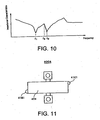
- FIG. 10 is a diagram showing the frequency-impedance characteristics of a specific configuration of the piezoelectric actuator.
- the frequency-impedance characteristics of the piezoelectric actuator 41 have an antiresonant frequency f 0 between the minimum value of the longitudinal oscillation (resonance frequency of the longitudinal oscillation) f 1 and the minimum value of the curved secondary oscillation (resonance frequency of the curved secondary oscillation) f 2 .
- the longitudinal oscillation resonance frequency f 1 is 284.3 kHz
- the curved secondary oscillation resonance frequency f 2 is 288.6 kHz. Therefore, it is possible to induce simultaneously longitudinal and curved secondary oscillations by setting the drive frequency (excitation frequency) of the piezoelectric actuator 41 at 280kHz to 290 kHz.
- a frequency between the longitudinal oscillation resonance frequency f 1 and the curved secondary oscillation resonance frequency f 2 is preferably set as the drive frequency of the piezoelectric actuator 41.
- the drive-frequency of the piezoelectric actuator should be greater than the antiresonant frequency f 0 located between the longitudinal oscillation resonance frequency f 1 and the curved secondary oscillation resonance frequency f 2 , and should be less than the curved secondary oscillation resonance frequency f 2 .
- FIG. 11 is an explanatory diagram of an example of the electrode arrangement of a piezoelectric actuator.
- the piezoelectric actuator 400A of the present modification is provided solely with a full electrode 404, as shown in FIG. 11 .
- a mechanically unbalanced state is created, and longitudinal and curved secondary oscillations are created by providing the piezoelectric actuator 41 with a balance section 41C1 and a contact section 41B1 in an unbalanced location instead of providing the piezoelectric actuator 41, which is an oscillator, with a contact section 41B.
- a contact section 41B1 and a balance section 41C1 are provided as contact sections, but the contact section 41B1 alone may also be provided.
- FIG. 12 is an explanatory diagram of the electrode arrangement for another piezoelectric actuator.
- the modification in FIG. 11 was configured with a full electrode 404, but the piezoelectric actuator 400B of the present embodiment can be configured with a drive electrode 405 and detection electrodes 406 disposed at a location in which the contact section 41B1 and balance section 41C1 are joined to each other, as shown in FIG 11 .
- the longitudinal oscillation of the piezoelectric elements is vibrated by the application of a drive voltage to the drive electrode 405, and an imbalance is created in the expansion and contraction of the piezoelectric elements. Furthermore, the curved secondary oscillation is reliably vibrated by the mechanically unbalanced state brought about by the contact section 41B1 and the balance section 41C1.
- the longitudinal and curved secondary oscillations are then combined to create elliptical oscillation.
- the detection electrodes 406 are used to detect the oscillation state for the same reasons as in the modification described above.
- the rotor was driven in one direction in the above description, but a configuration may also be adopted such that the rotor is driven both forwards and backwards.
- FIG. 13 is an explanatory diagram of the arrangement of electrodes in a piezoelectric actuator driven both forwards and backwards.
- the electrode arrangement in the piezoelectric actuator 400C of the present modification is configured so as to include a middle electrode 401 and two electrode pairs 402 and 403 disposed so as to intersect with the middle electrode 401.
- the middle electrode 401 and the electrode pair 402 are driven by the application of a drive voltage in order to achieve elliptical driving in a first direction (forward).
- a drive voltage is not applied to the electrode pair 403.
- the middle electrode 401 vibrates longitudinal oscillation, but an imbalance is created in the expansion and contraction of the longitudinal oscillation of the piezoelectric elements by applying a drive voltage solely to the electrode pair 402, and curved secondary oscillation in the first direction is vibrated.
- the longitudinal oscillation and the curved secondary oscillation are then combined to create elliptical oscillation of the in the first direction.
- the middle electrode 401 and the electrode pair 403 are driven by the application of a drive voltage in order to create an elliptical drive in the contact section 341B in a second direction (backwards).
- a drive voltage is not applied to the electrode pair 402.
- the longitudinal oscillation and the curved secondary oscillation are then combined to create elliptical oscillation 341 B in the second direction.
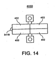
- FIG. 14 is an explanatory diagram of another arrangement of electrodes in a piezoelectric actuator driven both forwards and backwards.
- a middle electrode 401 and two electrode pairs 402 and 403 were provided in the modifications described above, but in the piezoelectric actuator 400D of the present modification, the middle electrode 401 is dispensed with and only the two electrode pairs 402 and 403 are provided as shown in FIG. 14 .
- the electrode pair 402 is driven by the application of a drive voltage in order to drive elliptically the contact section 341B in the first direction (forward).
- a drive voltage is not applied to the electrode pair 403.
- the longitudinal oscillation and the curved secondary oscillation are then combined to create elliptical oscillation in the first direction.
- the electrode pair 403 is driven by the application of a drive voltage in order to drive elliptically the contact section 341B in the second direction (backwards). A drive voltage is not applied to the electrode pair 402.
- the longitudinal oscillation and the curved secondary oscillation are then combined to create elliptical oscillation in the second direction.
- the electrodes to which a drive voltage is not applied are preferably used as detection electrodes to detect the oscillation state for the same reasons as in the modifications described above.
- the location at which the piezoelectric actuator is supported was not described in detail above, but it is possible to reduce oscillation loss by supporting the middle section, which is the oscillation node of both the longitudinal oscillation and the curved secondary oscillation.
- a drive device to a timing device was described above, but this approach is also applicable to other drive devices, such as analog display devices with analog pointers to display data other than time information; for example, temperature, air pressure, and other such natural physical quantities, as well as the pulse rate, respiration rate, and other biological measurements; or a drive device with a mechanical structure such as one that moves the arm of a mechanical doll.
- a piezoelectric actuator is used as a drive source for the time display unit, so the time display unit is not affected by the power generating operation of the power generator and the time can be accurately displayed.
- FIG. 15 is a partial plan view of the timing device relating to the fourth embodiment.
- FIG. 16 is a cross-sectional view of one part of the timing device relating to the fourth embodiment.
- FIG. 17 is a cross-sectional view of another part of the timing device relating to the fourth embodiment.
- the timing device 210 is a wristwatch designed for use by wrapping a belt coupled with the main body of the device around the wrist of the user.
- the timing device 210 includes a receiving circuit 211, an electric power source 212, a timing unit 213, and an operating unit 214.
- the receiving circuit 211 includes a first receiving crystal oscillator 221 for creating a first standard oscillation signal, a second receiving crystal oscillator 222 for creating a second standard oscillation signal, a receiving processor IC 223 for performing reception processing on the basis of the first standard oscillation signal and the second standard oscillation signal, and a coil antenna 224 for receiving externally transmitted electromagnetic waves.
- the electric power source 212 includes a battery 231 for supplying a source of electricity, and a battery terminal 232 for electrically connecting the battery 231 and the base plate.
- the timing unit 213 includes a second driving piezoelectric actuator 241 for driving a second hand as a pointer component, an hour/minute driving piezoelectric actuator 242 for driving an hour and minute hand as pointer components, a gear train section 243 for transmitting the driving force for driving the pointers, a standard oscillation signal crystal oscillator 244 for keeping time, and a timing IC 245 for performing various timing processes on the basis of the standard oscillation signals for timing.
- the gear train section 243 is similar to a regular analog timepiece and includes a second rotor 251, a second rotor pinion 252, a second intermediate wheel 253, a second wheel 254, a second hand 255, and a second rotor pressure member 256. Furthermore, the gear train section 243 also includes an hour/minute rotor 261, an hour/minute rotor pinion 262, a first hour/minute intermediate wheel 263, a second hour minute intermediate wheel 264, a center wheel and pinion 265, a minute hand 266, an hour wheel 267, an hour hand 268, a minute wheel 269, and a rotor pressure section 270.
- the operating unit 214 includes a setting stem 271, a first switch 272, a second witch 273, a setting lever 274, and a yoke 275, and is designed to be able to perform various settings including time setting and time correction, similar to common timing devices.
- the coil antenna 224 is disposed at a location in which the positive projection of the antenna on this plane does not overlap the positive projection of the second driving piezoelectric actuator 241 and the hour/minute driving piezoelectric actuator 242 on this plane, and is also disposed to form a space D1 with a specific distance ( FIG. 17 ) in a direction perpendicular to the thickness direction.
- Such an arrangement makes it possible to configure a thin wristwatch wherein the thickness of the timing device 210 can be reduced.
- the configuration of the second driving piezoelectric actuator and the hour/minute driving piezoelectric actuator is similar to those shown in FIGS. 4 through 7 and FIGS. 11 through 14 , so detailed descriptions are omitted.
- This angular momentum induces curved secondary oscillation whereby the second driving piezoelectric actuator 241 swings in the width direction, as shown in FIG. 6 .
- a greater degree of curved oscillation can be induced to create a greater angular momentum by disposing the contact section 41 B on the tip of the second driving piezoelectric actuator 241 opposite from the balance section 41C.
- the second rotor 251 is rotatably driven in the direction of displacement of the contact section 41 B while both types of pressure are large, or, in other words, when the contact section 41 B is in a position expanded toward the second rotor 251.
- the second driving piezoelectric actuator 241 rotatably drives the second rotor 251 by elliptical movement due to both the longitudinal oscillation and the curved oscillation.
- the second rotor 251 is pressed against the contact section of a second drive actuator by a second rotor pressure member 256.
- the second rotor 251 is therefore rotatably driven in a reliable manner.
- the rotational driving of the second rotor 251 causes the second rotor pinion 252 to rotate.
- the second intermediate wheel 253 interlocking with the second rotor pinion 252 is then rotatably driven.
- the second intermediate wheel 253 interlocks with the second wheel 254, causing the second hand 255 fixed to the second wheel 254 to move.
- the hour/minute driving piezoelectric actuator 242 rotatably drives the hour/minute rotor 261 by elliptical movement that results from a combination of longitudinal and curved oscillations. At this point, the hour/minute rotor 261 is pressed against the contact section of an hour/minute drive actuator by an hour/minute rotor pressure member 270. The hour/minute rotor 261 is therefore rotatably driven in a reliable manner.
- the rotational driving of the hour/minute rotor 261 causes the hour/minute rotor pinion 262 to rotate.
- the first hour/minute intermediate wheel 263 interlocking with the second hour/minute rotor pinion 262 is then rotatably driven.
- first hour/minute intermediate wheel 263 interlocks with the second hour minute intermediate wheel 264, causing the second hour minute intermediate wheel 264 to be rotatably driven.
- the second hour minute intermediate wheel 264 interlocks with the center wheel and pinion 265 and with the minute wheel 269 via the center wheel and pinion 265, and induces movement in the minute hand 266 fixed to the center wheel and pinion 265 and the hour hand 268 fixed to the hour wheel 267.
- the first receiving crystal oscillator 221 of the receiving circuit 211 creates a first standard oscillation signal corresponding to a 40-kHz LF standard wave, and outputs the signal to the receiving processor IC 223.
- the second receiving crystal oscillator 222 creates a second standard oscillation signal corresponding to a 60-kHz LF standard wave, and outputs the signal to the receiving processor IC 223.
- the coil antenna 224 configured as a ferrite antenna, for example, receives an LF standard wave on which time data are superposed.
- the receiving processor IC 223 demodulates the LF standard wave received by the coil antenna 224 as time data, stores the time data, and transmits the data to the timing IC.
- the receiving processor IC 223 is configured to include an AGC (Automatic Gain Control) circuit, an amplification circuit, a band-pass filter, a demodulation circuit, and a decoding circuit, all not shown.
- AGC Automatic Gain Control
- the amplification circuit of the receiving processor IC 223 amplifies the LF standard wave signal received by the coil antenna 224 under the gain control of the AGC circuit, and outputs the result to the band-pass filter.
- the band-pass filter extracts only specific frequency components from the amplified LF standard wave signal and outputs the result to the demodulation circuit.
- the demodulation circuit smoothes the inputted specific frequency components of the LF standard wave signal, demodulates the result, and outputs it to the decoding circuit.
- the decoding circuit decodes the demodulated LF standard wave signal, and outputs the result as a reception output signal.
- the AGC circuit controls the gain of the amplification circuit on the basis of the output signal of the demodulation circuit, and performs this control so that the reception level of the LF standard wave signal remains constant.
- a power save mode signal which is a signal for exerting control to reduce power consumption, is supplied from the timing IC 245, and the receiving processor IC 223 ceases to function when operation is not necessary.
- the receiving processor IC 223 is controlled by the power save mode signal so as to perform reception about once a day.
- the receiving operation is normally repeated many times when the time data cannot be received.
- Electromagnetic noise is not generated in the fourth embodiment and does not affect the reception of the LF standard waves because a piezoelectric actuator is used to drive the pointers. Therefore, the receiving operation of the receiving circuit 211 can be performed in conjunction with the pointer driving operation of the timing unit 213.
- LF standard waves can be received anytime and the time can be corrected. Furthermore, there is no need to provide a control procedure or circuit to stop driving the pointers during the receiving operation, and the control and circuit configuration can be simplified.
- the coil antenna 224 is disposed at a location in which the positive projection of the antenna on this plane does not overlap the positive projection of the second driving piezoelectric actuator 241 on this plane, and is also disposed to form a space with a specific distance in a direction perpendicular to the thickness direction.
- the coil antenna is disposed at a location in which at least part of the positive projection of the antenna on a plane perpendicular to the thickness direction of the timing device overlaps the positive projection of either the second driving piezoelectric actuator or the hour/minute driving piezoelectric actuator on the plane, and is also disposed to form a space with a specific distance in the thickness direction.
- FIG. 18 shows a cross-sectional view of part of the timing device of the fifth embodiment.
- the components in FIG. 18 similar to those in FIG. 16 or 17 are denoted by the same symbols.
- the coil antenna 224 is disposed at a location in which at least part of the positive projection of the coil antenna 224 on this plane overlaps the positive projection of the second driving piezoelectric actuator 241 on this plane, and is also disposed to form a space with a specific distance D2 in the thickness direction.
- LF standard waves can be received anytime to correct the time, similar to the fourth embodiment. Moreover, there is no need for a control procedure or circuit to stop driving the pointers during the receiving operation, and the control and circuit configuration can be simplified.
- a ferrite antenna is used as an antenna for receiving LF standard waves on which time information is superposed in the embodiments described above, but either a loop antenna or a ferrite antenna may be used when FM multiplex broadcasting (76 MHz to 108 MHz) on which time information is superposed is received, and either a microstrip antenna or a helical antenna may be used when electromagnetic waves (1.5 GHz) on which time information is superposed are received from a GPS satellite.
- the time information for the hours, minutes, and second is automatically corrected based on LF standard waves on which time information is superposed, but this process is not limited to the time display for hours, minutes, and second, and may include the automatic correction of a date display. Since date information is included in the LF standard waves as described above, the date display can be automatically corrected based on the LF standard waves when a piezoelectric actuator for driving a calendar display is included in addition to the piezoelectric actuator for driving the hour/minute/second display. In this case, an element for detecting the calendar display position may be added.
- LF standard waves were received as electromagnetic waves on which time information is superposed was used in the fourth and fifth embodiments described above, but it is also possible to use a configuration wherein a GPS signal, a pager signal in a FLEX-TD format, an FM multiplex signal, a CDMA signal, or other such various signals are used instead of LF standard waves.
- the communication process performed by the communication unit with the external communication device via the antenna is not affected, and can be performed in conjunction with the time display operation and the communication operation, because a piezoelectric actuator is used as the drive source for the time display unit.
Landscapes
- Physics & Mathematics (AREA)
- General Physics & Mathematics (AREA)
- General Electrical Machinery Utilizing Piezoelectricity, Electrostriction Or Magnetostriction (AREA)
- Electromechanical Clocks (AREA)
Claims (6)
- Zeitgebereinrichtung, umfassendeine Antenne (224)eine Kommunikationseinheit (211) zum Kommunizieren mit einer externen Kommunikationseinrichtung mittels der Antenne (224), undeine Zeitanzeigeeinheit (5, 213) auf der eine Zeitinformation durch eine mechanische Anordnung (61-63) angezeigt wird,wobei die Kommunikationseinheit (211) eine Empfangseinheit (211) zum Empfangen von einer Zeitinformation in einem bestimmten Zyklus von außen über die Antenne (224) und einen Momentanzeitzähler, zum sequentiellen Aktualisieren der momentanen Zeitinformation verwendend die Zeit, die der von der Empfangseinheit (211) empfangenen Zeitinformation entspricht, umfasst,
dadurch gekennzeichnet, dassdie Zeitanzeigeeinheit (5, 213) ausgebildet ist, um einen piezoelektrischen Aktuator (41) als einer Antriebsquelle zu verwenden und die Zeitinformation mit der mechanischen Anordnung (61-63) auf Basis der momentanen Zeitinformation anzuzeigen und dass die Einrichtung angeordnet ist, um die mechanische Struktur (61-63), während Funkwellensignale empfangen werden, anzutreiben. - Zeitgebereinrichtung nach Anspruch 1, dadurch gekennzeichnet, dassder piezoelektrische Aktuator (41) drehend einen Rotor (51) durch eine elliptische Bewegung, die sich aus einer Kombination aus Längsschwingung und kurvenförmiger Schwingung ergibt, antreibt.
- Zeitgebereinrichtung nach Anspruch 1, dadurch gekennzeichnet, dassder piezoelektrische Aktuator (41) eine oszillierende Platte, die durch Schichten eines plattenförmigen piezoelektrischen Elementes und einer Verstärkungsplatte (115) erhalten wird, einen Halteabschnitt (41A) zum Halten der oszillierenden Platte auf einer Stütze, und einen Kontaktabschnitt (41B), der an der Längsspitze der oszillierenden Platte vorgesehen ist, umfasst, unddas piezoelektrische Element (41) mit einem Antriebssignal versorgt wird, wodurch erwirkt wird, dass sich das piezoelektrische Element (41) expandiert und zusammenzieht, Expansions- und Zusammenziehoszillationen in der Längsrichtung und Oszillationen in der Richtung, die die Längsrichtung schneidet, in der oszillierenden Platte erzeugt werden, und ein Rotor (51) drehend durch den Versatz des Kontaktabschnittes, der diese Oszillationen begleitet, angetrieben wird.
- Zeitgebereinrichtung nach Anspruch 1, dadurch gekennzeichnet, dassdie Zeitanzeigeeinheit (5) einen Zeigerantriebsaktuator zum Antrieben von Zeigern (61-63), die die Zeitinformation anzeigen, umfasst, unddie Antenne (224) an einem Ort angeordnet ist, an dem die tatsächliche Erstreckung der Antenne (224) in einer Ebene, die senkrecht zu der Dickenrichtung der Zeitgebereinrichtung ist, die tatsächliche Erstreckung des piezoelektrischen Zeigerantriebsaktuators in der Ebene nicht überdeckt und ferner angeordnet ist, um um einen bestimmten Abstand in einer zu der Dickenrichtung senkrechten Richtung getrennt zu sein.
- Zeitgebereinrichtung nach Anspruch 1, dadurch gekennzeichnet, dassdie Zeitanzeigeeinheit (5) einen Zeigerantriebsaktuator zum Antreiben von Zeigern (61-63), die die Zeitinformation anzeigen, umfasst unddie Antenne (224) an einem Ort angeordnet ist an dem zumindest ein Teil der tatsächlichen Erstreckung der Antenne (224) in einer zu der Dickenrichtung der Zeitgebereinrichtung senkrechten Ebene die tatsächliche Erstreckung des piezoelektrischen Zeigerantriebsaktuators auf der Ebene überdeckt, und ferner angeordnet ist, um um einen bestimmten Abstand in der Dickenrichtung getrennt zu sein.
- Verfahren zum Steuern einer Zeitgebereinrichtung, umfassendeinen Zeitanzeigeschritt in dem ein piezoelektrischer Aktuator (41) als eine Antriebsquelle verwendet wird und in dem eine Zeitinformation durch eine mechanische Struktur (61-63) angezeigt wird,einen Kommunikationsschritt zum Kommunizieren mit einer externen Kommunikationseinrichtung in Verbindung mit dem Zeitanzeigeschritt mittels einer Antenne (224),einen Empfangsschritt zum Empfangen einer Zeitinformation in einem bestimmten Zyklus von außen mittels der Antenne (224),einen Momentanzeitzählschritt zum sequentiellen aktualisieren der momentanen Zeitinformation verwendend die bereits empfangene Zeitinformation als Bezug, undeinen Zeitanzeigeschritt, in dem der piezoelektrische Aktuator (41) angetrieben wird und Zeitinformation durch eine mechanische Struktur auf Basis der Momentanzeitinformation angezeigt wird und in dem die Einrichtung die mechanische Struktur (61-63) antreibt, während Funkwellensignale empfangen werden.
Applications Claiming Priority (5)
| Application Number | Priority Date | Filing Date | Title |
|---|---|---|---|
| JP2003044341 | 2003-02-21 | ||
| JP2003044341 | 2003-02-21 | ||
| JP2003094255 | 2003-03-31 | ||
| JP2003094255 | 2003-03-31 | ||
| PCT/JP2004/001955 WO2004074945A1 (ja) | 2003-02-21 | 2004-02-20 | 駆動装置、計時装置および計時装置の制御方法 |
Publications (3)
| Publication Number | Publication Date |
|---|---|
| EP1494096A1 EP1494096A1 (de) | 2005-01-05 |
| EP1494096A4 EP1494096A4 (de) | 2008-07-02 |
| EP1494096B1 true EP1494096B1 (de) | 2010-02-03 |
Family
ID=32911429
Family Applications (1)
| Application Number | Title | Priority Date | Filing Date |
|---|---|---|---|
| EP04713171A Expired - Lifetime EP1494096B1 (de) | 2003-02-21 | 2004-02-20 | Zeitgebervorrichtung und verfahren zur steuerung der zeitgebervorrichtung |
Country Status (5)
| Country | Link |
|---|---|
| US (2) | US20040233794A1 (de) |
| EP (1) | EP1494096B1 (de) |
| JP (1) | JPWO2004074945A1 (de) |
| DE (1) | DE602004025403D1 (de) |
| WO (1) | WO2004074945A1 (de) |
Families Citing this family (10)
| Publication number | Priority date | Publication date | Assignee | Title |
|---|---|---|---|---|
| JP3596548B2 (ja) * | 2002-03-27 | 2004-12-02 | セイコーエプソン株式会社 | 電子時計および電子機器 |
| JP2006242745A (ja) * | 2005-03-03 | 2006-09-14 | Seiko Epson Corp | 電子機器 |
| TWI454865B (zh) * | 2013-05-06 | 2014-10-01 | Princo Corp | 腕錶結構、腕錶用的電子機芯及腕錶的製造方法 |
| TWI489227B (zh) * | 2013-05-06 | 2015-06-21 | 巨擘科技股份有限公司 | 腕錶結構、腕錶用的電子旋鈕以及顯示器型腕錶 |
| CN104142623A (zh) * | 2013-05-06 | 2014-11-12 | 巨擘科技股份有限公司 | 腕表结构及腕表用的电子机芯 |
| EP3128666B1 (de) | 2014-03-31 | 2019-05-08 | Citizen Watch Co., Ltd. | Elektronische vorrichtung |
| JP6011819B2 (ja) * | 2014-06-26 | 2016-10-19 | セイコーエプソン株式会社 | 電子腕時計 |
| KR101597232B1 (ko) * | 2014-07-22 | 2016-02-24 | 이지하 | 표시부가 자동정렬되는 디스플레이장치 |
| EP3168695B1 (de) * | 2015-11-13 | 2021-03-10 | ETA SA Manufacture Horlogère Suisse | Testverfahren für ganggenauigkeit einer quartzuhr |
| EP4092492B1 (de) | 2021-05-21 | 2025-07-23 | ETA SA Manufacture Horlogère Suisse | Uhrwerk, das einen generator umfasst |
Citations (1)
| Publication number | Priority date | Publication date | Assignee | Title |
|---|---|---|---|---|
| JP2002214367A (ja) * | 2000-02-10 | 2002-07-31 | Seiko Epson Corp | 計時装置 |
Family Cites Families (19)
| Publication number | Priority date | Publication date | Assignee | Title |
|---|---|---|---|---|
| CH685183A5 (fr) * | 1991-08-30 | 1995-04-13 | Asulab Sa | Moteur piézo-électrique. |
| JPH05273361A (ja) * | 1992-03-24 | 1993-10-22 | Seiko Instr Inc | 超音波モータ付電子機器 |
| JPH0837785A (ja) * | 1994-07-22 | 1996-02-06 | Seiko Instr Inc | 超音波モータ及び超音波モータ付き電子機器 |
| FR2741488B1 (fr) * | 1995-11-16 | 1998-01-09 | Asulab Sa | Procede et circuit d'excitation et de controle d'un moteur piezo-electrique en mode pas a pas |
| JP3165070B2 (ja) * | 1997-04-25 | 2001-05-14 | セイコーインスツルメンツ株式会社 | カレンダ付電子時計 |
| CN1241322A (zh) * | 1997-08-04 | 2000-01-12 | 精工爱普生株式会社 | 传动装置及使用它的钟表和通知装置 |
| DE29714185U1 (de) * | 1997-08-08 | 1998-12-03 | Gebrüder Junghans GmbH, 78713 Schramberg | Funkarmbanduhr |
| JP3551433B2 (ja) * | 1998-01-22 | 2004-08-04 | セイコーエプソン株式会社 | 携帯電子機器 |
| JP4510179B2 (ja) * | 1998-08-07 | 2010-07-21 | セイコーインスツル株式会社 | 超音波モータおよび超音波モータ付電子機器 |
| JP3721888B2 (ja) * | 1998-12-04 | 2005-11-30 | セイコーエプソン株式会社 | 携帯用電子機器および携帯用電子機器の制御方法 |
| EP2568595A3 (de) * | 1998-12-21 | 2013-05-15 | Seiko Epson Corporation | Piezoelektrischer Aktor, Uhrwerk und tragbares Gerät |
| JP4376342B2 (ja) * | 1999-03-02 | 2009-12-02 | セイコーインスツル株式会社 | 電子時計 |
| JP2000354013A (ja) * | 1999-06-10 | 2000-12-19 | Seiko Clock Inc | 長波標準電波の受信テスタ |
| JP4337178B2 (ja) * | 1999-07-14 | 2009-09-30 | カシオ計算機株式会社 | 表示付受信装置 |
| US6850468B2 (en) * | 1999-09-17 | 2005-02-01 | Seiko Epson Corporation | Electronic timepiece, control method for electronic timepiece, regulating system for electronic timepiece, and regulating method for electronic timepiece |
| JP4770043B2 (ja) * | 2001-03-27 | 2011-09-07 | セイコーエプソン株式会社 | 圧電アクチュエータの駆動装置、圧電アクチュエータの駆動方法、時計および携帯機器 |
| JP3772763B2 (ja) * | 2002-02-28 | 2006-05-10 | セイコーエプソン株式会社 | 日付表示機能付電子時計 |
| JP3454269B1 (ja) * | 2002-03-26 | 2003-10-06 | セイコーエプソン株式会社 | 電波修正時計および電波修正時計の制御方法 |
| JP3596548B2 (ja) * | 2002-03-27 | 2004-12-02 | セイコーエプソン株式会社 | 電子時計および電子機器 |
-
2004
- 2004-02-19 US US10/780,903 patent/US20040233794A1/en not_active Abandoned
- 2004-02-20 EP EP04713171A patent/EP1494096B1/de not_active Expired - Lifetime
- 2004-02-20 DE DE602004025403T patent/DE602004025403D1/de not_active Expired - Lifetime
- 2004-02-20 JP JP2005502777A patent/JPWO2004074945A1/ja active Pending
- 2004-02-20 WO PCT/JP2004/001955 patent/WO2004074945A1/ja not_active Ceased
-
2006
- 2006-06-28 US US11/476,060 patent/US20060245304A1/en not_active Abandoned
Patent Citations (1)
| Publication number | Priority date | Publication date | Assignee | Title |
|---|---|---|---|---|
| JP2002214367A (ja) * | 2000-02-10 | 2002-07-31 | Seiko Epson Corp | 計時装置 |
Also Published As
| Publication number | Publication date |
|---|---|
| DE602004025403D1 (de) | 2010-03-25 |
| EP1494096A4 (de) | 2008-07-02 |
| US20060245304A1 (en) | 2006-11-02 |
| JPWO2004074945A1 (ja) | 2006-06-01 |
| WO2004074945A1 (ja) | 2004-09-02 |
| US20040233794A1 (en) | 2004-11-25 |
| EP1494096A1 (de) | 2005-01-05 |
Similar Documents
| Publication | Publication Date | Title |
|---|---|---|
| KR100605776B1 (ko) | 전자 시계 및 전자 기기 | |
| CN100487607C (zh) | 具有无线通信功能的电子钟表 | |
| US7078847B2 (en) | Piezoelectric actuator, timepiece, and portable device | |
| US7583564B2 (en) | Piezoelectric actuator and electronic equipment with piezoelectric actuator | |
| KR100605775B1 (ko) | 전자 시계 및 전자 기기 | |
| EP1494096B1 (de) | Zeitgebervorrichtung und verfahren zur steuerung der zeitgebervorrichtung | |
| JP4144356B2 (ja) | 圧電アクチュエータおよびその駆動回路 | |
| JP3387101B2 (ja) | アクチュエータ、およびそれを用いた時計並びに報知装置 | |
| JPH11264882A (ja) | 発電装置付電子時計 | |
| JPWO1999007063A1 (ja) | アクチュエータ、およびそれを用いた時計並びに報知装置 | |
| JP3719061B2 (ja) | 圧電アクチュエータ、時計および携帯機器 | |
| JPH05281370A (ja) | アナログ電子時計 | |
| JP5076533B2 (ja) | 駆動装置 | |
| JP4770043B2 (ja) | 圧電アクチュエータの駆動装置、圧電アクチュエータの駆動方法、時計および携帯機器 | |
| JP2002354853A (ja) | アクチュエータ、およびそれを用いた時計並びに報知装置 | |
| JP4218666B2 (ja) | 圧電アクチュエータ、および電子機器 | |
| JP2006343240A (ja) | 時計ムーブメントおよび時計 | |
| JP3832260B2 (ja) | 圧電アクチュエータ、時計および携帯機器 | |
| JP2017191028A (ja) | 電子時計 | |
| JP4507501B2 (ja) | 圧電アクチュエータの駆動装置、時計、および電子機器 | |
| JP2000188882A (ja) | 駆動装置、カレンダー表示装置、携帯機器および時計 | |
| JP4385630B2 (ja) | アナログ電子時計 | |
| JP2004077491A (ja) | 電子時計および電子機器 | |
| CN115032873B (zh) | 电子钟表 | |
| CN1698019A (zh) | 驱动装置、计时装置和计时装置的控制方法 |
Legal Events
| Date | Code | Title | Description |
|---|---|---|---|
| PUAI | Public reference made under article 153(3) epc to a published international application that has entered the european phase |
Free format text: ORIGINAL CODE: 0009012 |
|
| 17P | Request for examination filed |
Effective date: 20041103 |
|
| AK | Designated contracting states |
Kind code of ref document: A1 Designated state(s): AT BE BG CH CY CZ DE DK EE ES FI FR GB GR HU IE IT LI LU MC NL PT RO SE SI SK TR |
|
| AX | Request for extension of the european patent |
Extension state: AL LT LV MK |
|
| DAX | Request for extension of the european patent (deleted) | ||
| RBV | Designated contracting states (corrected) |
Designated state(s): CH DE FR GB LI |
|
| A4 | Supplementary search report drawn up and despatched |
Effective date: 20080530 |
|
| 17Q | First examination report despatched |
Effective date: 20090210 |
|
| GRAP | Despatch of communication of intention to grant a patent |
Free format text: ORIGINAL CODE: EPIDOSNIGR1 |
|
| RTI1 | Title (correction) |
Free format text: TIMER DEVICE, AND METHOD OF CONTROLLING TIMER DEVICE |
|
| GRAS | Grant fee paid |
Free format text: ORIGINAL CODE: EPIDOSNIGR3 |
|
| GRAA | (expected) grant |
Free format text: ORIGINAL CODE: 0009210 |
|
| AK | Designated contracting states |
Kind code of ref document: B1 Designated state(s): CH DE FR GB LI |
|
| REG | Reference to a national code |
Ref country code: GB Ref legal event code: FG4D |
|
| REG | Reference to a national code |
Ref country code: CH Ref legal event code: EP |
|
| REF | Corresponds to: |
Ref document number: 602004025403 Country of ref document: DE Date of ref document: 20100325 Kind code of ref document: P |
|
| REG | Reference to a national code |
Ref country code: CH Ref legal event code: PL |
|
| PG25 | Lapsed in a contracting state [announced via postgrant information from national office to epo] |
Ref country code: CH Free format text: LAPSE BECAUSE OF NON-PAYMENT OF DUE FEES Effective date: 20100228 Ref country code: LI Free format text: LAPSE BECAUSE OF NON-PAYMENT OF DUE FEES Effective date: 20100228 |
|
| PLBE | No opposition filed within time limit |
Free format text: ORIGINAL CODE: 0009261 |
|
| STAA | Information on the status of an ep patent application or granted ep patent |
Free format text: STATUS: NO OPPOSITION FILED WITHIN TIME LIMIT |
|
| 26N | No opposition filed |
Effective date: 20101104 |
|
| REG | Reference to a national code |
Ref country code: FR Ref legal event code: PLFP Year of fee payment: 13 |
|
| REG | Reference to a national code |
Ref country code: FR Ref legal event code: PLFP Year of fee payment: 14 |
|
| PGFP | Annual fee paid to national office [announced via postgrant information from national office to epo] |
Ref country code: FR Payment date: 20170112 Year of fee payment: 14 Ref country code: DE Payment date: 20170214 Year of fee payment: 14 |
|
| PGFP | Annual fee paid to national office [announced via postgrant information from national office to epo] |
Ref country code: GB Payment date: 20170215 Year of fee payment: 14 |
|
| REG | Reference to a national code |
Ref country code: DE Ref legal event code: R119 Ref document number: 602004025403 Country of ref document: DE |
|
| GBPC | Gb: european patent ceased through non-payment of renewal fee |
Effective date: 20180220 |
|
| REG | Reference to a national code |
Ref country code: FR Ref legal event code: ST Effective date: 20181031 |
|
| PG25 | Lapsed in a contracting state [announced via postgrant information from national office to epo] |
Ref country code: DE Free format text: LAPSE BECAUSE OF NON-PAYMENT OF DUE FEES Effective date: 20180901 |
|
| PG25 | Lapsed in a contracting state [announced via postgrant information from national office to epo] |
Ref country code: FR Free format text: LAPSE BECAUSE OF NON-PAYMENT OF DUE FEES Effective date: 20180228 Ref country code: GB Free format text: LAPSE BECAUSE OF NON-PAYMENT OF DUE FEES Effective date: 20180220 |