EP1494098B1 - Dispositif de commande pour technique de sécurité et procédé de commande - Google Patents
Dispositif de commande pour technique de sécurité et procédé de commande Download PDFInfo
- Publication number
- EP1494098B1 EP1494098B1 EP03015212A EP03015212A EP1494098B1 EP 1494098 B1 EP1494098 B1 EP 1494098B1 EP 03015212 A EP03015212 A EP 03015212A EP 03015212 A EP03015212 A EP 03015212A EP 1494098 B1 EP1494098 B1 EP 1494098B1
- Authority
- EP
- European Patent Office
- Prior art keywords
- potentiometer
- test
- voltage
- accordance
- test device
- Prior art date
- Legal status (The legal status is an assumption and is not a legal conclusion. Google has not performed a legal analysis and makes no representation as to the accuracy of the status listed.)
- Expired - Lifetime
Links
- 238000000034 method Methods 0.000 title claims abstract description 13
- 238000012360 testing method Methods 0.000 claims abstract description 44
- 238000011156 evaluation Methods 0.000 claims description 9
- 238000005259 measurement Methods 0.000 description 3
- 230000002950 deficient Effects 0.000 description 2
- 238000001514 detection method Methods 0.000 description 2
- 238000010586 diagram Methods 0.000 description 1
- 230000000694 effects Effects 0.000 description 1
- 238000004519 manufacturing process Methods 0.000 description 1
Images
Classifications
-
- G—PHYSICS
- G01—MEASURING; TESTING
- G01D—MEASURING NOT SPECIALLY ADAPTED FOR A SPECIFIC VARIABLE; ARRANGEMENTS FOR MEASURING TWO OR MORE VARIABLES NOT COVERED IN A SINGLE OTHER SUBCLASS; TARIFF METERING APPARATUS; MEASURING OR TESTING NOT OTHERWISE PROVIDED FOR
- G01D3/00—Indicating or recording apparatus with provision for the special purposes referred to in the subgroups
- G01D3/08—Indicating or recording apparatus with provision for the special purposes referred to in the subgroups with provision for safeguarding the apparatus, e.g. against abnormal operation, against breakdown
-
- G—PHYSICS
- G05—CONTROLLING; REGULATING
- G05B—CONTROL OR REGULATING SYSTEMS IN GENERAL; FUNCTIONAL ELEMENTS OF SUCH SYSTEMS; MONITORING OR TESTING ARRANGEMENTS FOR SUCH SYSTEMS OR ELEMENTS
- G05B9/00—Safety arrangements
- G05B9/02—Safety arrangements electric
Definitions
- the present invention relates to a control device with a potentiometer and a test device according to the preamble of claim 1.
- the present invention relates to a corresponding method for controlling a device according to the preamble of claim 5.
- Such control devices and methods are known from DE 43 22nd 472 A1, US 5,812,411 and EP 1 022 570 A2.
- the object of the present invention is therefore to propose a control device and a corresponding control method with which an increased reliability of a potentiometer to be evaluated can be ensured.
- the invention provides a method for controlling a device having the features according to claim 5.
- the electrical resistance used is an ohmic resistance, which is connected in series with the potentiometer.
- the test device comprises a second ohmic resistor which is connected in series with the potentiometer and the first ohmic resistor on the potentiometer side. If this series circuit is operated as a voltage divider between an operating voltage and ground, the potentials at the terminals of the potentiometer are different from the operating voltage and ground, so that short circuits to the operating voltage or ground can be detected.
- a center tap of the potentiometer and a connection point between the potentiometer and the fixed electrical resistance can be evaluated in terms of voltage.
- a short circuit between the terminals of the potentiometer with each other or from the terminals of the potentiometer to an operating voltage or ground can be determined.
- the voltage states on the potentiometer can be evaluated analog or digital.
- a second test device can be connected in parallel to said first test device. This means in practice that two controllers are used in one safety device.
- a safety-related control unit is used, for example, to control the machine overrun after an EMERGENCY STOP.
- the load circuit of the machine is switched staggered over time.
- an RC circuit As a timer serves this purpose an RC circuit.
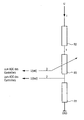
- the resistor is realized as a potentiometer R3.
- the potentiometer R3 is grounded via an ohmic resistor R1. With its other terminal, the potentiometer R3 is applied to a reference voltage U via a second ohmic resistor R2.
- a reference voltage U typically the operating voltage of the controller or controller is used.
- the center tap 3 of the potentiometer R3 supplies a voltage value U (val) which is used by the control unit for the control. For this purpose, the voltage value is applied to the analog / digital converter of the controller.
- U (test) a test voltage from the junction 2 between the first ohmic resistor R1 and the potentiometer R3 is also supplied to the analog-to-digital converter ABC of the controller.
- the voltage U (val) to be evaluated is proportional to the test current I.
- U (val) and U (test) can be used to reveal the errors shown in the table below.
- KS means a short circuit and the numbers 1, 2 and 3 denote the respective terminals of the potentiometer. If the potentiometer is defective, for example, to the effect that there is a short circuit between terminals 1 and 2 of potentiometer R3 according to the first row of the table, then an excessively high test voltage U (test) occurs, since current I is significantly higher than in the faultless state is. A comparison with a setpoint provides the indication that the potentiometer is defective.
- test voltage U (test) also deviates from the set point because of the resistance of the potentiometer R3 corresponds only to the resistance between the terminals 2 and 3.
- a short circuit between terminals 2 and 3 of potentiometer R3 also results in a "false", i. from the setpoint deviating test voltage U (test).
- the error cases that the terminals 1 and 2 of the potentiometer R3 are open, can be detected on the basis of the test voltage U (test), since this is zero, but should be greater than zero.
- the voltage U (val) is equal to zero. This is outside the specified range specified in the table and an error is made. The same applies if the terminal 3 is short-circuited to the operating voltage U. Then, namely, the voltage U (val) has the value U, which is also outside the desired range.
- test voltage U (test) with the value U is above its desired value. Finally, if the terminal 1 is short-circuited to the operating voltage U, then too large a test voltage U (test) results.
- the evaluation of the two signals U (val) and U (test) for the detection of errors at the potentiometer R3 is essentially independent of the thermal drift of the resistors, so that a fault of the potentiometer can be detected with high certainty.
Landscapes
- Physics & Mathematics (AREA)
- General Physics & Mathematics (AREA)
- Engineering & Computer Science (AREA)
- Automation & Control Theory (AREA)
- Testing Of Short-Circuits, Discontinuities, Leakage, Or Incorrect Line Connections (AREA)
- Safety Devices In Control Systems (AREA)
- Air Bags (AREA)
Claims (8)
- Appareil de commande comportant- un potentiomètre (R3), qui est évaluable pour la production d'un signal de commande, et- un dispositif de test pour la vérification du potentiomètre (R3) quant à son éventuelle défectuosité,- le dispositif de test comprenant une résistance ohmique fixe (R1) qui est branchée en série avec le potentiomètre (R3) et qui est évaluable pour sa part de telle sorte que l'évaluation de la résistance (R1) fournit une conclusion sur l'éventuelle défectuosité du potentiomètre (R3),caractérisé par le fait que le dispositif de test comprend une deuxième résistance ohmique fixe (R2) qui est branchée en série avec le potentiomètre (R3) et avec la première résistance ohmique (R1) du côté du potentiomètre.
- Appareil de commande selon la revendication 1, dans lequel, avec le dispositif de test, une prise médiane (3) du potentiomètre (R3) et un point de liaison (2) entre le potentiomètre (R3) et la résistance électrique fixe (R1) sont évaluables en tension.
- Appareil de commande selon la revendication 2, dans lequel, en combinant les deux tensions, un court-circuit entre les bornes (1 à 3) du potentiomètre (R3) ou un court-circuit des bornes du potentiomètre (R3) à une tension de fonctionnement ou à une masse est détectable.
- Appareil de commande selon l'une des revendications précédentes, dans lequel un deuxième dispositif de test est branché en parallèle avec le dispositif de test mentionné pour permettre une évaluation redondante.
- Procédé de commande d'un appareil par- évaluation d'un potentiomètre (R3) pour la production d'un signal de commande, et- vérification du potentiomètre (R3) quant à son éventuelle défectuosité,- la vérification du potentiomètre (R3) comprenant une évaluation d'une résistance ohmique fixe (R1) qui est reliée électriquement au potentiomètre (R3) et qui est branchée en série avec le potentiomètre (R3),caractérisé par le fait qu'une deuxième résistance ohmique (R2) est branchée en série avec le potentiomètre (R3) et avec la première résistance ohmique (R1) du côté du potentiomètre.
- Procédé selon la revendication 5, dans lequel on évalue en tension une prise médiane (3) du potentiomètre (R3) et un point de liaison (2) entre le potentiomètre (R3) et la résistance électrique fixe (R1).
- Procédé selon la revendication 6, dans lequel, en combinant les deux tensions, on détecte un court-circuit entre les bornes (1 à 3) du potentiomètre (R3) ou un court-circuit des bornes du potentiomètre (R3) à une tension de fonctionnement ou à une masse.
- Procédé selon l'une des revendications 5 à 7, dans lequel la vérification du potentiomètre (R3) est effectuée deux fois, indépendamment l'une de l'autre.
Priority Applications (3)
| Application Number | Priority Date | Filing Date | Title |
|---|---|---|---|
| DE50303481T DE50303481D1 (de) | 2003-07-04 | 2003-07-04 | Steuergerät für die Sicherheitstechnik und entsprechendes Steuerungsverfahren |
| EP03015212A EP1494098B1 (fr) | 2003-07-04 | 2003-07-04 | Dispositif de commande pour technique de sécurité et procédé de commande |
| AT03015212T ATE327526T1 (de) | 2003-07-04 | 2003-07-04 | Steuergerät für die sicherheitstechnik und entsprechendes steuerungsverfahren |
Applications Claiming Priority (1)
| Application Number | Priority Date | Filing Date | Title |
|---|---|---|---|
| EP03015212A EP1494098B1 (fr) | 2003-07-04 | 2003-07-04 | Dispositif de commande pour technique de sécurité et procédé de commande |
Publications (2)
| Publication Number | Publication Date |
|---|---|
| EP1494098A1 EP1494098A1 (fr) | 2005-01-05 |
| EP1494098B1 true EP1494098B1 (fr) | 2006-05-24 |
Family
ID=33427127
Family Applications (1)
| Application Number | Title | Priority Date | Filing Date |
|---|---|---|---|
| EP03015212A Expired - Lifetime EP1494098B1 (fr) | 2003-07-04 | 2003-07-04 | Dispositif de commande pour technique de sécurité et procédé de commande |
Country Status (3)
| Country | Link |
|---|---|
| EP (1) | EP1494098B1 (fr) |
| AT (1) | ATE327526T1 (fr) |
| DE (1) | DE50303481D1 (fr) |
Families Citing this family (2)
| Publication number | Priority date | Publication date | Assignee | Title |
|---|---|---|---|---|
| DE102005048601B3 (de) * | 2005-10-06 | 2007-04-05 | Pilz Gmbh & Co. Kg | Vorrichtung und Verfahren zum fehlersicheren Auswerten eines Stellungsgebers, insbesondere eines Potentiometers |
| EP2511719A1 (fr) * | 2011-04-15 | 2012-10-17 | Siemens Aktiengesellschaft | Procédé de détermination d'une fonction erronée d'un potentiomètre |
Family Cites Families (4)
| Publication number | Priority date | Publication date | Assignee | Title |
|---|---|---|---|---|
| DE3522775A1 (de) * | 1985-06-26 | 1987-01-08 | Daimler Benz Ag | Vorrichtung zur bestimmung des rbergangswiderstandes am schleifer eines potentiometers |
| DE4322472B4 (de) * | 1993-07-06 | 2006-03-09 | Siemens Ag | Schaltungsanordnung zur Überwachung eines Stellungsgebers |
| US5812411A (en) * | 1995-07-14 | 1998-09-22 | Calabrese; Joseph S. | Tapped variable potentiometer resistor with current sense and safety circuit |
| US6181141B1 (en) * | 1999-01-22 | 2001-01-30 | Honeywell Inc. | Failsafe monitoring system for potentiometers and monitor interface |
-
2003
- 2003-07-04 DE DE50303481T patent/DE50303481D1/de not_active Expired - Lifetime
- 2003-07-04 EP EP03015212A patent/EP1494098B1/fr not_active Expired - Lifetime
- 2003-07-04 AT AT03015212T patent/ATE327526T1/de not_active IP Right Cessation
Also Published As
| Publication number | Publication date |
|---|---|
| EP1494098A1 (fr) | 2005-01-05 |
| ATE327526T1 (de) | 2006-06-15 |
| DE50303481D1 (de) | 2006-06-29 |
Similar Documents
| Publication | Publication Date | Title |
|---|---|---|
| EP0277955B1 (fr) | Dispositif de surveillance pour une installation de commande electronique dans un vehicule automobile | |
| DE102012212123B4 (de) | Vorrichtung zur Diagnose einer Schaltungsanordnung | |
| DE4441070C2 (de) | Sicherheitsschalteranordnung | |
| EP1134589B1 (fr) | Méthode de détection d'une connection fautive de masse dans un circuit électrique, en particulier d'un véhicule | |
| DE102007022210B3 (de) | Mehrstufiges Verbindersystem für medizinische Verwendung | |
| DE10347979A1 (de) | Diagnostizierbare Schalteranordnung | |
| EP4131849B1 (fr) | Élément de circuit, composant pse et procédé de surveillance et de protection d'un réseau podl | |
| DE102005016127B4 (de) | Sensorsystem | |
| EP1494098B1 (fr) | Dispositif de commande pour technique de sécurité et procédé de commande | |
| EP1034553B1 (fr) | Circuit de surveillance d'un commutateur a courant alternatif | |
| EP1594021A1 (fr) | Dispositif de circuit et procédé de test de contacts de commutation d'un circuit numérique de sortie | |
| EP1431768A1 (fr) | Procédé et dispositif de mesure de la résistivité d'un élément de résistance sensible à la température | |
| EP0609261B1 (fr) | Systeme de controle d'un systeme de commande electrique | |
| EP2511719A1 (fr) | Procédé de détermination d'une fonction erronée d'un potentiomètre | |
| WO2019105646A1 (fr) | Appareil de saisie tactile pour un véhicule et procédé de fonctionnement d'un tel appareil de saisie tactile | |
| WO2004086069A1 (fr) | Procede d'essai de composants d'une plaquette de circuit imprime | |
| EP0815459A1 (fr) | Circuits et procede de controle de generateurs non intermittents de signaux | |
| EP0694451B1 (fr) | Dispositif de sécurité pour véhicule | |
| DE102024127109B4 (de) | Elektro-Motor-Steuerschaltung, Lenksäule und Verfahren zu deren Betriebszustandsbestimmung | |
| EP3837497B1 (fr) | Transformateur comprenant un circuit de test | |
| WO2021048232A1 (fr) | Capteur de batterie | |
| DE19640120A1 (de) | Schaltungsanordnung und Verfahren zur Überprüfung einer Schaltungs-Matrix | |
| EP0927356B2 (fr) | Procede de verification de composants electriques et dispositif permettant de mettre ledit procede en oeuvre | |
| DE102023127259A1 (de) | Steuergerät mit wenigstens einer Schnittstelle für einen Sensor und Anordnung aus diesem Steuergerät und dem Sensor, der über eine Leitung an die Schnittstelle des Steuergerätes angeschlossen ist | |
| DE102023212557A1 (de) | Verfahren und Vorrichtung zum Erkennen eines sicherheitsrelevanten Fehlers an einer Endstufe mit einer geschalteten Last |
Legal Events
| Date | Code | Title | Description |
|---|---|---|---|
| PUAI | Public reference made under article 153(3) epc to a published international application that has entered the european phase |
Free format text: ORIGINAL CODE: 0009012 |
|
| AK | Designated contracting states |
Kind code of ref document: A1 Designated state(s): AT BE BG CH CY CZ DE DK EE ES FI FR GB GR HU IE IT LI LU MC NL PT RO SE SI SK TR |
|
| AX | Request for extension of the european patent |
Extension state: AL LT LV MK |
|
| 17P | Request for examination filed |
Effective date: 20050207 |
|
| 17Q | First examination report despatched |
Effective date: 20050303 |
|
| AKX | Designation fees paid |
Designated state(s): AT BE BG CH CY CZ DE DK EE ES FI FR GB GR HU IE IT LI LU MC NL PT RO SE SI SK TR |
|
| GRAP | Despatch of communication of intention to grant a patent |
Free format text: ORIGINAL CODE: EPIDOSNIGR1 |
|
| GRAS | Grant fee paid |
Free format text: ORIGINAL CODE: EPIDOSNIGR3 |
|
| GRAA | (expected) grant |
Free format text: ORIGINAL CODE: 0009210 |
|
| AK | Designated contracting states |
Kind code of ref document: B1 Designated state(s): AT BE BG CH CY CZ DE DK EE ES FI FR GB GR HU IE IT LI LU MC NL PT RO SE SI SK TR |
|
| PG25 | Lapsed in a contracting state [announced via postgrant information from national office to epo] |
Ref country code: SK Free format text: LAPSE BECAUSE OF FAILURE TO SUBMIT A TRANSLATION OF THE DESCRIPTION OR TO PAY THE FEE WITHIN THE PRESCRIBED TIME-LIMIT Effective date: 20060524 Ref country code: RO Free format text: LAPSE BECAUSE OF FAILURE TO SUBMIT A TRANSLATION OF THE DESCRIPTION OR TO PAY THE FEE WITHIN THE PRESCRIBED TIME-LIMIT Effective date: 20060524 Ref country code: FI Free format text: LAPSE BECAUSE OF FAILURE TO SUBMIT A TRANSLATION OF THE DESCRIPTION OR TO PAY THE FEE WITHIN THE PRESCRIBED TIME-LIMIT Effective date: 20060524 Ref country code: SI Free format text: LAPSE BECAUSE OF FAILURE TO SUBMIT A TRANSLATION OF THE DESCRIPTION OR TO PAY THE FEE WITHIN THE PRESCRIBED TIME-LIMIT Effective date: 20060524 Ref country code: IE Free format text: LAPSE BECAUSE OF FAILURE TO SUBMIT A TRANSLATION OF THE DESCRIPTION OR TO PAY THE FEE WITHIN THE PRESCRIBED TIME-LIMIT Effective date: 20060524 Ref country code: NL Free format text: LAPSE BECAUSE OF FAILURE TO SUBMIT A TRANSLATION OF THE DESCRIPTION OR TO PAY THE FEE WITHIN THE PRESCRIBED TIME-LIMIT Effective date: 20060524 Ref country code: CZ Free format text: LAPSE BECAUSE OF FAILURE TO SUBMIT A TRANSLATION OF THE DESCRIPTION OR TO PAY THE FEE WITHIN THE PRESCRIBED TIME-LIMIT Effective date: 20060524 |
|
| REG | Reference to a national code |
Ref country code: GB Ref legal event code: FG4D Free format text: NOT ENGLISH |
|
| REG | Reference to a national code |
Ref country code: CH Ref legal event code: EP |
|
| REG | Reference to a national code |
Ref country code: CH Ref legal event code: NV Representative=s name: SIEMENS SCHWEIZ AG |
|
| REG | Reference to a national code |
Ref country code: IE Ref legal event code: FG4D Free format text: LANGUAGE OF EP DOCUMENT: GERMAN |
|
| REF | Corresponds to: |
Ref document number: 50303481 Country of ref document: DE Date of ref document: 20060629 Kind code of ref document: P |
|
| GBT | Gb: translation of ep patent filed (gb section 77(6)(a)/1977) |
Effective date: 20060612 |
|
| PG25 | Lapsed in a contracting state [announced via postgrant information from national office to epo] |
Ref country code: MC Free format text: LAPSE BECAUSE OF NON-PAYMENT OF DUE FEES Effective date: 20060731 Ref country code: BE Free format text: LAPSE BECAUSE OF NON-PAYMENT OF DUE FEES Effective date: 20060731 |
|
| PG25 | Lapsed in a contracting state [announced via postgrant information from national office to epo] |
Ref country code: DK Free format text: LAPSE BECAUSE OF FAILURE TO SUBMIT A TRANSLATION OF THE DESCRIPTION OR TO PAY THE FEE WITHIN THE PRESCRIBED TIME-LIMIT Effective date: 20060824 |
|
| PG25 | Lapsed in a contracting state [announced via postgrant information from national office to epo] |
Ref country code: ES Free format text: LAPSE BECAUSE OF FAILURE TO SUBMIT A TRANSLATION OF THE DESCRIPTION OR TO PAY THE FEE WITHIN THE PRESCRIBED TIME-LIMIT Effective date: 20060904 |
|
| REG | Reference to a national code |
Ref country code: SE Ref legal event code: TRGR |
|
| PG25 | Lapsed in a contracting state [announced via postgrant information from national office to epo] |
Ref country code: PT Free format text: LAPSE BECAUSE OF FAILURE TO SUBMIT A TRANSLATION OF THE DESCRIPTION OR TO PAY THE FEE WITHIN THE PRESCRIBED TIME-LIMIT Effective date: 20061024 |
|
| NLV1 | Nl: lapsed or annulled due to failure to fulfill the requirements of art. 29p and 29m of the patents act | ||
| REG | Reference to a national code |
Ref country code: IE Ref legal event code: FD4D |
|
| ET | Fr: translation filed | ||
| PLBE | No opposition filed within time limit |
Free format text: ORIGINAL CODE: 0009261 |
|
| STAA | Information on the status of an ep patent application or granted ep patent |
Free format text: STATUS: NO OPPOSITION FILED WITHIN TIME LIMIT |
|
| 26N | No opposition filed |
Effective date: 20070227 |
|
| PG25 | Lapsed in a contracting state [announced via postgrant information from national office to epo] |
Ref country code: AT Free format text: LAPSE BECAUSE OF NON-PAYMENT OF DUE FEES Effective date: 20060704 |
|
| BERE | Be: lapsed |
Owner name: SIEMENS A.G. Effective date: 20060731 |
|
| PG25 | Lapsed in a contracting state [announced via postgrant information from national office to epo] |
Ref country code: GR Free format text: LAPSE BECAUSE OF FAILURE TO SUBMIT A TRANSLATION OF THE DESCRIPTION OR TO PAY THE FEE WITHIN THE PRESCRIBED TIME-LIMIT Effective date: 20060825 |
|
| PG25 | Lapsed in a contracting state [announced via postgrant information from national office to epo] |
Ref country code: EE Free format text: LAPSE BECAUSE OF FAILURE TO SUBMIT A TRANSLATION OF THE DESCRIPTION OR TO PAY THE FEE WITHIN THE PRESCRIBED TIME-LIMIT Effective date: 20060524 Ref country code: BG Free format text: LAPSE BECAUSE OF FAILURE TO SUBMIT A TRANSLATION OF THE DESCRIPTION OR TO PAY THE FEE WITHIN THE PRESCRIBED TIME-LIMIT Effective date: 20060824 |
|
| PG25 | Lapsed in a contracting state [announced via postgrant information from national office to epo] |
Ref country code: TR Free format text: LAPSE BECAUSE OF FAILURE TO SUBMIT A TRANSLATION OF THE DESCRIPTION OR TO PAY THE FEE WITHIN THE PRESCRIBED TIME-LIMIT Effective date: 20060524 Ref country code: LU Free format text: LAPSE BECAUSE OF NON-PAYMENT OF DUE FEES Effective date: 20060704 Ref country code: HU Free format text: LAPSE BECAUSE OF FAILURE TO SUBMIT A TRANSLATION OF THE DESCRIPTION OR TO PAY THE FEE WITHIN THE PRESCRIBED TIME-LIMIT Effective date: 20061125 |
|
| PG25 | Lapsed in a contracting state [announced via postgrant information from national office to epo] |
Ref country code: CY Free format text: LAPSE BECAUSE OF FAILURE TO SUBMIT A TRANSLATION OF THE DESCRIPTION OR TO PAY THE FEE WITHIN THE PRESCRIBED TIME-LIMIT Effective date: 20060524 |
|
| REG | Reference to a national code |
Ref country code: CH Ref legal event code: PCAR Free format text: SIEMENS SCHWEIZ AG;INTELLECTUAL PROPERTY FREILAGERSTRASSE 40;8047 ZUERICH (CH) |
|
| REG | Reference to a national code |
Ref country code: FR Ref legal event code: PLFP Year of fee payment: 14 |
|
| REG | Reference to a national code |
Ref country code: FR Ref legal event code: PLFP Year of fee payment: 15 |
|
| REG | Reference to a national code |
Ref country code: CH Ref legal event code: PCOW Free format text: NEW ADDRESS: WERNER-VON-SIEMENS-STRASSE 1, 80333 MUENCHEN (DE) |
|
| REG | Reference to a national code |
Ref country code: FR Ref legal event code: PLFP Year of fee payment: 16 |
|
| PGFP | Annual fee paid to national office [announced via postgrant information from national office to epo] |
Ref country code: CH Payment date: 20191002 Year of fee payment: 17 |
|
| PGFP | Annual fee paid to national office [announced via postgrant information from national office to epo] |
Ref country code: GB Payment date: 20200813 Year of fee payment: 18 |
|
| PGFP | Annual fee paid to national office [announced via postgrant information from national office to epo] |
Ref country code: SE Payment date: 20200713 Year of fee payment: 18 |
|
| REG | Reference to a national code |
Ref country code: CH Ref legal event code: PL |
|
| PG25 | Lapsed in a contracting state [announced via postgrant information from national office to epo] |
Ref country code: CH Free format text: LAPSE BECAUSE OF NON-PAYMENT OF DUE FEES Effective date: 20200731 Ref country code: LI Free format text: LAPSE BECAUSE OF NON-PAYMENT OF DUE FEES Effective date: 20200731 |
|
| GBPC | Gb: european patent ceased through non-payment of renewal fee |
Effective date: 20210704 |
|
| PG25 | Lapsed in a contracting state [announced via postgrant information from national office to epo] |
Ref country code: GB Free format text: LAPSE BECAUSE OF NON-PAYMENT OF DUE FEES Effective date: 20210704 |
|
| PG25 | Lapsed in a contracting state [announced via postgrant information from national office to epo] |
Ref country code: SE Free format text: LAPSE BECAUSE OF NON-PAYMENT OF DUE FEES Effective date: 20210705 |
|
| PGFP | Annual fee paid to national office [announced via postgrant information from national office to epo] |
Ref country code: IT Payment date: 20220720 Year of fee payment: 20 Ref country code: DE Payment date: 20220620 Year of fee payment: 20 |
|
| PGFP | Annual fee paid to national office [announced via postgrant information from national office to epo] |
Ref country code: FR Payment date: 20220721 Year of fee payment: 20 |
|
| P01 | Opt-out of the competence of the unified patent court (upc) registered |
Effective date: 20230510 |
|
| REG | Reference to a national code |
Ref country code: DE Ref legal event code: R071 Ref document number: 50303481 Country of ref document: DE |