EP1494179A2 - Machine pour rendre la monnaie - Google Patents
Machine pour rendre la monnaie Download PDFInfo
- Publication number
- EP1494179A2 EP1494179A2 EP04380134A EP04380134A EP1494179A2 EP 1494179 A2 EP1494179 A2 EP 1494179A2 EP 04380134 A EP04380134 A EP 04380134A EP 04380134 A EP04380134 A EP 04380134A EP 1494179 A2 EP1494179 A2 EP 1494179A2
- Authority
- EP
- European Patent Office
- Prior art keywords
- coin
- sorter
- blade
- change
- situated
- Prior art date
- Legal status (The legal status is an assumption and is not a legal conclusion. Google has not performed a legal analysis and makes no representation as to the accuracy of the status listed.)
- Withdrawn
Links
- 230000008859 change Effects 0.000 title claims abstract description 92
- 238000000605 extraction Methods 0.000 claims abstract description 38
- 238000005096 rolling process Methods 0.000 claims description 20
- 238000001514 detection method Methods 0.000 claims description 10
- 230000003287 optical effect Effects 0.000 claims description 6
- 238000002347 injection Methods 0.000 claims description 3
- 239000007924 injection Substances 0.000 claims description 3
- 238000013461 design Methods 0.000 description 13
- 238000004873 anchoring Methods 0.000 description 10
- 230000006870 function Effects 0.000 description 8
- 239000002184 metal Substances 0.000 description 5
- 230000007246 mechanism Effects 0.000 description 4
- 230000002250 progressing effect Effects 0.000 description 4
- 230000015556 catabolic process Effects 0.000 description 3
- 230000001276 controlling effect Effects 0.000 description 3
- 238000005286 illumination Methods 0.000 description 3
- 239000007788 liquid Substances 0.000 description 3
- 238000011084 recovery Methods 0.000 description 3
- 238000003860 storage Methods 0.000 description 3
- 239000000956 alloy Substances 0.000 description 2
- 229910045601 alloy Inorganic materials 0.000 description 2
- 230000000694 effects Effects 0.000 description 2
- 239000000463 material Substances 0.000 description 2
- 230000009467 reduction Effects 0.000 description 2
- 230000002829 reductive effect Effects 0.000 description 2
- XLYOFNOQVPJJNP-UHFFFAOYSA-N water Substances O XLYOFNOQVPJJNP-UHFFFAOYSA-N 0.000 description 2
- 230000032683 aging Effects 0.000 description 1
- 238000005452 bending Methods 0.000 description 1
- 230000005465 channeling Effects 0.000 description 1
- 238000004891 communication Methods 0.000 description 1
- 230000007423 decrease Effects 0.000 description 1
- 230000003247 decreasing effect Effects 0.000 description 1
- 230000001419 dependent effect Effects 0.000 description 1
- 239000000428 dust Substances 0.000 description 1
- 238000005516 engineering process Methods 0.000 description 1
- 239000000284 extract Substances 0.000 description 1
- 239000012467 final product Substances 0.000 description 1
- 230000006872 improvement Effects 0.000 description 1
- 230000005764 inhibitory process Effects 0.000 description 1
- 238000003780 insertion Methods 0.000 description 1
- 230000037431 insertion Effects 0.000 description 1
- 230000002452 interceptive effect Effects 0.000 description 1
- 238000005304 joining Methods 0.000 description 1
- 230000000670 limiting effect Effects 0.000 description 1
- 238000005259 measurement Methods 0.000 description 1
- 239000012528 membrane Substances 0.000 description 1
- 238000000034 method Methods 0.000 description 1
- 238000000465 moulding Methods 0.000 description 1
- 230000008569 process Effects 0.000 description 1
- 239000000047 product Substances 0.000 description 1
- 238000002310 reflectometry Methods 0.000 description 1
- 230000001105 regulatory effect Effects 0.000 description 1
- 230000000284 resting effect Effects 0.000 description 1
- 238000000926 separation method Methods 0.000 description 1
- 238000004513 sizing Methods 0.000 description 1
- 238000012800 visualization Methods 0.000 description 1
Images





Classifications
-
- G—PHYSICS
- G07—CHECKING-DEVICES
- G07F—COIN-FREED OR LIKE APPARATUS
- G07F5/00—Coin-actuated mechanisms; Interlocks
- G07F5/24—Coin-actuated mechanisms; Interlocks with change-giving
-
- G—PHYSICS
- G07—CHECKING-DEVICES
- G07D—HANDLING OF COINS OR VALUABLE PAPERS, e.g. TESTING, SORTING BY DENOMINATIONS, COUNTING, DISPENSING, CHANGING OR DEPOSITING
- G07D3/00—Sorting a mixed bulk of coins into denominations
- G07D3/14—Apparatus driven under control of coin-sensing elements
Definitions
- the present invention relates to a change giver of the type used in machines, the operation of which is carried out by means of introducing one or more coins of sufficient value to obtain the requested product or service.
- the function of a change giver within this type of automatic vending machines is to carry out the entire sales process, i.e. the recognition of all the programmed coins, their appraisal and classification of, for example, four types of them, for their subsequent use as returned change.
- these change givers also enable, for example, using suitable reading devices, the acceptance of different bills, as well as bank or pre-payment cards.
- the change giver usually includes the following main components:
- the function of the selector is to validate and appraise the different coins introduced. To that end the selector has the information corresponding to the features of the coins to be accepted and compares them with those of the introduced coins.
- the parameters or features of the coin which the selector usually measures are: sound of the coin when striking against, for example, a metal part, size of the coin and electrical and magnetic features of the material or materials making up the coin.
- the function of the sorter is to divert the coins towards the change tube corresponding to their value, or towards the vault or towards the return chute, always according to the value of the coin, the filled condition of the tubes or of other external conditions imposed by the vending machine.
- the coin extractor system allows for the individual and unitary extraction of the coins stored in the change tubes, which are what store the coins which will be used as coins for change.
- the invention relates to a change giver according to claim 1; preferred embodiments of the change giver are defined in the dependent claims.
- the change giver for automatic vending machines of the invention includes a coin selector, situated above a coin sorter, which in turn is situated above four change tubes, which tubes are substantially arranged in single file, an extraction system for extracting the coins stored in the change tubes and a casing; said sorter comprises:
- the sorter furthermore comprises:
- the substantially vertical upper branch of the fourth blade is slightly curved, being a concave curve on which the coin stops in its forward movement through the change giver, the change giver being in its assembly position.
- the change giver preferably includes electromagnet actuation control means; more preferably, said actuation control means consist of feeding the electromagnets by means of a short pulse train.
- the sorter preferably includes coin passage detection means, including an optical system of the emitter-receiver type measuring the reflection in the coin, in which the emitter is fed by means of pulses and the reflected signal is measured by means of the receiver both in the instances of time in which the emitter is active and during those in which it remains inactive, calculating the difference between the two states and providing a coin detection signal when the difference exceeds a determined threshold.
- coin passage detection means including an optical system of the emitter-receiver type measuring the reflection in the coin, in which the emitter is fed by means of pulses and the reflected signal is measured by means of the receiver both in the instances of time in which the emitter is active and during those in which it remains inactive, calculating the difference between the two states and providing a coin detection signal when the difference exceeds a determined threshold.
- Figure 1 shows the main components of the change giver, arranged according to a preferred embodiment of the present invention:
- the selector 10 used in the present change giver is similar to that disclosed in Spanish patent application number 200101875, filed by Azkoyen Medios de Pago, S.A. on 9 August, 2001, and related to a "coin selector". Therefore, the selector 10 is made up of independent modules which can be mechanically, electrically and/or optically coupled to one another and/or on a frame.
- the selector 10 includes a sensor module, including a path in which a coin 100 has a series of sensors capable of detecting the value and validity of the coins.
- the selector measures different features of the progressing coin related to its dimensions, elasticity and electromagnetic features of the alloy or alloys making up the coin.
- the selector elaborates a series of parameters related to the measurements previously made and compares them with those stored in its internal memory, which correspond to the programmed valid coins.
- the progressing coin will thus be identified with a certain denomination or, on the contrary, will be recognized as not valid. In any case, the progressing coin will pass towards the sorter to be accepted or rejected, and in the event it is accepted, it will be directed towards the vault or towards one of the change tubes.
- the sorter is an electromechanical module situated immediately after the selector, according to the forward movement path of the coin, which has the function of diverting the progressing coin from an inlet opening corresponding with the outlet of the selector, towards different outlet openings or chutes, according to the result of the analysis carried out by the selector and of the filled conditions of the tubes or of other conditions external to the change giver, such as time inhibitions of certain types of coins for example.
- the preferred embodiment of the sorter 20 is shown in Figures 2 to 7.
- the coin In its path, the coin is encountered with a first acceptance or rejection bifurcation defined by the blade P1 and by a second one defined by the blade P2, to direct the coin towards the vault or towards the tubes.
- the recovery is directed towards the front portion, such that on one hand, a better outlet of the rejected coins is provided, and on the other, more space is provided for the coins going to the vault.
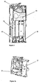
- the general support 21 supports the assembly formed by the selector 10 and sorter 20; the front 22 of the sorter is designed to adapt the outlet of the unaccepted coins to the rejection path.
- Figure 2c shows the lower portion of the sorter, and the outlets from the sorter to the four change tubes (A), (B), (C) and (D), to the vault (H) and to recovery (R) are detailed.
- the electromagnet B1 is actuated, as shown in Figure 3.
- This electromagnet B1 is responsible for actuating the "acceptance-rejection" blade P1, causing a linear shifting (shown by the arrow F1) in the part 24, which is converted into a rotation (shown by the arrow F2) in the horizontal lower shaft of the blade P1. If the coin should not be accepted, the blade P1 remains in its standstill position, and the coin runs to the return through a rolling ramp provided on the lower portion of the front 22 of the sorter.
- Figure 4 also shows the central support 25 on which the plane change blade P3 is assembled.
- the sorting of the tubes is achieved as a result of a plane change system, which is carried out by means of the "plane change" blade P3.
- This vertical shaft blade is assembled on the central support 25, such that it intercepts the path of the coin.
- the blade P3 is situated under the platform 26 and to one side thereof, in the coin rolling direction.
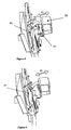
- the coin is diverted to the front or rear portion of the sorter by means of the "plane change" blade P3 (actuated by electromagnet B3).
- a linear shifting shown by the arrow F3 of Figures 5 and 6) of the part 24' occurs, causing a rotation (shown by the arrow F4 of Figures 5 and 6) in the vertical shaft of the blade P3.
- the blade P3 has a rolling track on its lower portion extending towards the front portion, on a tilted plane, and towards the back portion, on a substantially horizontal plane, of the sorter. In the case shown in Figure 5, the blade P3 is positioned towards the front portion of the sorter, thus opening the path for the coins to go through the rolling track extending towards the rear portion, towards the tubes A or C.
- Figure 6 shows a view similar to that of Figure 5, but in this case the blade P3 is positioned towards the rear portion of the sorter, thus opening the path for the coins to go through the rolling track extending towards the front portion, directing them to the tubes D or B.
- the sorter also includes the linear shifting blade P4 (actuated by B4), which is situated under the plane change blade and which consists of an L-shaped blade, the branches of which extend towards the rear and front portion of the sorter, a section of coin rolling track constituting the lower branch of the L; two grooves have been made in respective branches of the L, such that according to whether or not the blade P4 is actuated by its corresponding electromagnet B4, the coin will follow one path or another.
- the linear shifting blade P4 actuated by B4
- the coin in the event that the electromagnet B3 is deactivated, if the blade P4 is actuated, the coin will fall through the groove provided on the lower branch (towards tube C), or if not, it will roll through the section of rolling track and then fall through the groove provided on the vertical branch (towards tube A).
- the electromagnet B3 is actuated, whether or not the blade P4 is actuated, the coin will roll through the section of rolling track and will traverse the groove of the vertical branch (towards tube B), or it will strike against the vertical branch of the blade P4 which will re-guide it towards tube D.
- a ramp of this type is situated at the rear portion of the front of the sorter, and also on the platform 26 of the central support ( Figure 7a), where the plane change blade P3 is assembled.
- Another design aspect taken into account in the sorter of the invention consists of the fact that the width of the chutes ranges between 4 and 5 mm to facilitate a proper flow of the coins.
- the return area has a width of 9 mm in order to thus be able to simultaneously expel up to three coins.
- the anti-remanence metal stop in the front portion of the movable metal part has been removed, replacing it with an extra injection of plastic, such that it forms a stop in the plastic rather than doing so on the metal part, thus eliminating remanence problems.
- Another improvement introduced by the electromagnets used consists of the optimum design of the cones which are machined in the fixed and movable cores, thus achieving a better performance and therefore a lower power consumption.
- Control of the electromagnets has also been optimized. To that end, a control is carried out by means of a variable duration pulse train, decreasing the working cycle when the electromagnet has carried out its stroke, rather than a long impulse, significantly reducing the value of the intensity necessary for actuating the electromagnet. This favorably affects the total consumption of the change giver and therefore in the sizing of other elements, such as the power supply source.
- the detection of the passage of the coins from the outlets of the sorter towards the tubes and the filling thereof is carried out by means of an optical system made up of photodiode pairs, such as an infrared emitter and phototransistor, such as a detector of the light reflected by the coin in the detection area.
- the coin reflection detection system has also been optimized to achieve high reliability, even in unfavorable conditions, as is the case of dirty coins or coins of a high ambient illumination. To that end, rather than using the detector only at the electrical levels corresponding to the cutoff or saturation, the entire dynamic margin is used, being connected to an analog-digital converter.
- the emitter rather than continuously feeding the emitter, it is fed at higher intensity pulses than if it were continuously fed, but if a reduced working cycle is maintained, the mean consumption significantly decreases.
- the detection area is illuminated with short duration pulses and the signal provided by the detector both when the emitter is actuated and when it remains at rest is measured.
- the electronic control system based on a microcontroller will calculate the difference between the signals obtained with and without actuation of the emitter.
- signals occurring in "common mode" such as the external illumination and other types of noises, are eliminated.
- Low reflectivity coins are also detected, given that the system thus constructed makes very little noise and, and therefore small value detection thresholds can be established.
- the upper cover 27 of the sorter + selector assembly is collapsible, which improves access thereof.
- the front cover 28 of the sorter shown in Figure 12b is likewise modular and easily removable, such that different versions can be assembled, according to the desired final product; this front cover includes the visualization, communication and control elements.
- the cover includes a membrane keyboard with five keys 280 (four keys for programming the tubes and one key for accessing the program), and with a single light indicator, typically a light emitting diode (LED) 281 which reports the functional state of the change giver; and also a small alphanumerical screen or display 283 with two lines of sixteen characters each, through which the state of the change giver is reported at all times, and it allows changing easily and safely the internal parameters of the change giver.
- a membrane keyboard with five keys 280 (four keys for programming the tubes and one key for accessing the program), and with a single light indicator, typically a light emitting diode (LED) 281 which reports the functional state of the change giver; and also a small alphanumerical screen or display 283 with two lines of sixteen characters each, through which the state of the change giver is reported at all times, and it allows changing easily and safely the internal parameters of the change giver.
- LED light emitting diode
- the extraction system 40 used in the present change giver is that disclosed in Spanish patent application number 200203012, filed by Azkoyen Medios de Pago, S.A. on 26 December, 2002 and relating to a "coin payout mechanism".
- This extraction system is modular, and there will therefore be one extraction module for each change tube, each module being independent and interchangeable.
- the extraction of the coins for each tube is carried out by means of a mechanism which, every time it is actuated, extracts and gives the coin at all times occupying the lower position in the change tube.
- each extraction mechanism is constituted of two coplanar discs rotating in opposite directions which are situated just below the coin containing tube, the rotating shaft of said discs being parallel to the shaft of the tube.
- Each of these discs bears a pin of a height exceeding the separation between the disc and change tube.
- the pins thereof define circular paths which are secant with the projection of the containing tube. These pins shift in their paths without interfering with the wall of the tube, to which end said wall may have notches to enable the passage of the pins, or the pins may be retractable, shifting in a downward direction when crossing the wall of the tube.
- the shifting of the pins according to their circular path occurs between an inoperative position in which they are situated outside of the outline of the change tube, and an extraction position, in which they are situated within the outline of the change tube, resting on and pushing against the edge of the coin occupying the lower position in the containing tube to move it towards the exterior of said tube, through a notch the tube will have after the lower edge of its wall.
- the pins are situated and assembled such that every time only one of them acts against the edge of the coins and without there being a collision between said pins and the wall of the containing tube.
- European patent application EP 903,702 A2 discloses a device of utility in the extraction of coins in which the shafts of the motor, gear motor and coin container, are coaxially arranged such that the total space taken up by the extractor mechanism is reduced.
- the gear motor used is of the planetary type. Unlike all of this, in the proposed device, disclosed in detail in Spanish patent application ES200203012, the motor is arranged with the shaft perpendicular to that of the extractor discs and therefore to that of the shaft of the change tube.
- the control of each of these motors is carried out by means of PWM (Pulse Wave Modulation), regulating the extraction speed of the coin according to the coin load existing in the change tube.
- PWM Pulse Wave Modulation
- an optical detector connected with the position of the extraction pins is assembled on the extraction module, and a connection to an inlet of the analog-digital converter of the microcontroller is arranged to measure the voltage in terminals of the motor of the extractor module at all times.
- the power delivered to the motor can be modified by controlling the working cycle (ratio between the connection time and disconnection time of the motor) by means of PWM, and thus controlling the revolutions in the motor, off-setting the effect of the coin load.
- This extractor system allows fast anchoring of the change tubes, facilitating assembly and removal thereof; the anchoring can be carried out for each extraction module, as shown in Figure 8, by means of a dovetailed grooving and tonguing joint 31, 31' finished off with a clip 32. Therefore, each change tube 30 will have a dovetail joint 31 solidly fixed thereto, which fits with another one 31' of the upper part of the extraction system 40.
- FIGs 9 and 10 show a manner of anchoring each module of the extraction system to the casing of the change giver.
- This anchoring consists of a multiple retainer 41 fixed to the lower base of the casing, for example by means of screws; this multiple retainer consists of a system of guides 42 plus clips 43; the clips slightly bend, and one the introduction of the extraction module has concluded, each clip returns to its standstill position, preventing the movement of the extraction system in the direction contrary to its insertion.
- These clips are removable to facilitate the possible changing of the module in the event of a breakdown.
- a rotating handle 44 has been provided on the lower and outer part of each extraction module, facilitating the disassembly eliminating the risk of causing breakdowns during handling.
- One of the novelty features of the extraction system 40 is a section of rolling ramp 46 which has been provided in alignment with the change tube D.
- the placement of this tube D also called fourth tube, is determined by the geometry offered by the different existing standards.
- the coins of this tube in the first place are extracted by sliding (as occurs with the coins of the other tubes), and then they roll along this section of ramp to the outlet of the sliding ramp.
- the control of the secure minimum change level in the tubes is carried out by means of a reflexive-type optical system, of the same type and functionality as the one used for detection of the passage of the coins from the sorter to the different tubes.
- a reflexive-type optical system of the same type and functionality as the one used for detection of the passage of the coins from the sorter to the different tubes.
- the reflection caused by the column of coins in the corresponding tube is analyzed.
- the manner of working makes the detector be highly immune to high levels of illumination or different states of aging of the coins, therefore being able to detect with certainty the minimum level of coins required to carry out a secure change.
- the change tubes have a funnel shape in their upper part, which aids in the collection of coins from the sorter.
- demarcating stops 48 of the thickness of the outlet coins have been provided, which will depend on the type of coins which can be stored in each change tube.
- Each demarcating stop 48 consists of a part with a front flap 481, anchoring the part to the change tube 30 by the bending of a clip 482. By varying the dimensions of the flap, the passage of coins of different thicknesses is achieved through the space remaining between said part and the support base of the coins.
- the stop is introduced in a housing of the change tube 30 provided for that purpose, this housing being in a direction perpendicular to the shaft of the tube. Thus the same change tube can be used for different coins.
- the auto-load system provides no problems of a coin remaining in the vertical position.
- the casing has as important functions:
- one of the main novelty features of the plastic casing of this change giver is that it includes numerous ribs 51 on its sides (transverse ribs), central portion (in grids) and lower portion (diamond-shaped- see Figure 19) to provide rigidity thereto.
- the casing 50 likewise has a casing-sorter anchoring which is released by means of a movable angular retainer 52 of a metal support part 53 (see Figure 21), supporting the anchoring of the change giver to the vending machine, and a retractable telescopic handle 54 facilitating its transport (see Figures 21 and 22).
- the casing has on its lower portion a multiple retainer 41 guiding and then clipping the extraction system and the corresponding tubes.
- the casing houses the sliding ramp 45 of the coins from the extractor system to the exterior: by means of this cylindrical design, the coin is turned over, passing it from a horizontal outlet to a vertical outlet for better channeling thereof.
- This special design furthermore serves as an anti-theft design.
- the casing also has a special design (see Figure 23) for evacuating possible liquid entering in the change giver, such that the electronic part is leak-tight, preventing liquid from being introduced in the control boards and causing breakdowns.
- the casing has a series of transverse guides 55 with outer grooves 56 and a series of cylindrical openings 57 on the side portion of the casing 50, such that the water (and dust) is redirected, for example, towards the channel of the vault.
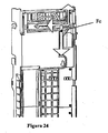
- Another one of the special features of the design of the casing is that it allows making a loop with the bundle of cables, following the path indicated by the arrow Fc (see Figure 24), to prevent disconnections or breakage of cables from occurring when the bundle is pulled on; it furthermore includes an embedded fastening which, in addition to serving as a complete fastening of the bundle of cables, serves as an anti-water (leak-tight) system.
- the configuration of the assembly of the casing has a special molding for the purpose of providing it with mechanical rigidity and making it leak-tight; it is not a simple "U" as are the known designs.
- the casing is provided with a decorative cover 59 to access the tubes, with an opening system 590 by means of a spring.
- the electronics of the change giver is designed such that it has the ability of connection in vending machines having both the Executive, MDB ICP 2.0 protocol, as well as BDV.
- the change giver can be reprogrammed through an external programming tool; this function is carried out by means of an RS-232 outlet, which allows:
- the electronics of the change giver are based on low consumption technology. This is achieved through the control card, which has control functions over the feeding of the other modules, such that it has the ability to disconnect itself if its activity is not necessary in a determined period of time.
- the idea of reducing consumption as much as possible, as previously explained, has been taken into account in the control of the electromagnets of the sorter, extraction motors and optical detectors.
- the change giver has a complete accounting control: number and types of coins, number and types of sales, events,...; it allows for internally storing events so that subsequently, if the user so desires, he or she can have access to the details of these events.
- the change giver also has the ability to inform the user at all times of its functional state by means of light indicators, for example LED diodes situated in the sorter and/or by means of the display.
- the operating program of the change giver is carried out such that:
Landscapes
- Physics & Mathematics (AREA)
- General Physics & Mathematics (AREA)
- Control Of Vending Devices And Auxiliary Devices For Vending Devices (AREA)
Applications Claiming Priority (2)
| Application Number | Priority Date | Filing Date | Title |
|---|---|---|---|
| ES200301519 | 2003-06-30 | ||
| ES200301519 | 2003-06-30 |
Publications (1)
| Publication Number | Publication Date |
|---|---|
| EP1494179A2 true EP1494179A2 (fr) | 2005-01-05 |
Family
ID=33427388
Family Applications (1)
| Application Number | Title | Priority Date | Filing Date |
|---|---|---|---|
| EP04380134A Withdrawn EP1494179A2 (fr) | 2003-06-30 | 2004-06-29 | Machine pour rendre la monnaie |
Country Status (1)
| Country | Link |
|---|---|
| EP (1) | EP1494179A2 (fr) |
Cited By (1)
| Publication number | Priority date | Publication date | Assignee | Title |
|---|---|---|---|---|
| EP1840847A1 (fr) * | 2006-03-27 | 2007-10-03 | Coges S.p.A. | Dispositif de verrouillage de tiroir dans un distributeur de monnaie |
-
2004
- 2004-06-29 EP EP04380134A patent/EP1494179A2/fr not_active Withdrawn
Cited By (1)
| Publication number | Priority date | Publication date | Assignee | Title |
|---|---|---|---|---|
| EP1840847A1 (fr) * | 2006-03-27 | 2007-10-03 | Coges S.p.A. | Dispositif de verrouillage de tiroir dans un distributeur de monnaie |
Similar Documents
| Publication | Publication Date | Title |
|---|---|---|
| CA2324005C (fr) | Compte-billets international personnalisable | |
| EP0137637A2 (fr) | Système de traitement de pièces de monnaie | |
| US3443107A (en) | Radiation sensitive currency testing device | |
| US4412607A (en) | Vending machine with improved means for dispensing products at a predetermined price | |
| US8517213B2 (en) | Vending machine user interface guide; electronic coin return; and hinged delivery bin | |
| WO1998024067A1 (fr) | Systeme de traitement de fonds | |
| KR920020365A (ko) | 화폐정리장치 | |
| EP0803844B1 (fr) | Magasin de pièces de monnaie | |
| US5715924A (en) | Game play media lending machine, for which bank notes can be used | |
| EP1494179A2 (fr) | Machine pour rendre la monnaie | |
| JP2002279473A (ja) | 硬貨選別装置 | |
| CA2388693C (fr) | Trieuse de monnaie avec leviers de triages | |
| US6109416A (en) | Method of operating a bill and coin changer | |
| EP1168256A2 (fr) | Procédé de fonctionnement d'un mécanisme de pièces de monnaie | |
| US5564549A (en) | Switch for the distribution of coins | |
| US5377809A (en) | Coin control systems for automatic machines | |
| CN1176443A (zh) | 自动售货机的硬币储存状态检测装置和方法 | |
| US876126A (en) | Vending-machine. | |
| KR101006776B1 (ko) | 자동판매기의 동전 처리 시스템 및 방법 | |
| EP0612045A1 (fr) | Ameliorations a des systemes de commande de pieces de monnaie pour machines de distribution automatique | |
| KR101054521B1 (ko) | 자동판매기의 동전 처리 시스템 및 방법 | |
| JP2005352841A (ja) | 自動販売機 | |
| KR19990041114U (ko) | 자동판매기의 반환버튼장치 | |
| GB2242050A (en) | Coin escrow unit | |
| MXPA99001097A (fr) |
Legal Events
| Date | Code | Title | Description |
|---|---|---|---|
| PUAI | Public reference made under article 153(3) epc to a published international application that has entered the european phase |
Free format text: ORIGINAL CODE: 0009012 |
|
| AK | Designated contracting states |
Kind code of ref document: A2 Designated state(s): AT BE BG CH CY CZ DE DK EE ES FI FR GB GR HU IE IT LI LU MC NL PL PT RO SE SI SK TR |
|
| AX | Request for extension of the european patent |
Extension state: AL HR LT LV MK |
|
| STAA | Information on the status of an ep patent application or granted ep patent |
Free format text: STATUS: THE APPLICATION HAS BEEN WITHDRAWN |
|
| 18W | Application withdrawn |
Effective date: 20050203 |