EP1494248B1 - Isolierhülse mit Schlitz - Google Patents
Isolierhülse mit Schlitz Download PDFInfo
- Publication number
- EP1494248B1 EP1494248B1 EP04011060A EP04011060A EP1494248B1 EP 1494248 B1 EP1494248 B1 EP 1494248B1 EP 04011060 A EP04011060 A EP 04011060A EP 04011060 A EP04011060 A EP 04011060A EP 1494248 B1 EP1494248 B1 EP 1494248B1
- Authority
- EP
- European Patent Office
- Prior art keywords
- insulation tube
- tube according
- restraining means
- insulation
- restraining
- Prior art date
- Legal status (The legal status is an assumption and is not a legal conclusion. Google has not performed a legal analysis and makes no representation as to the accuracy of the status listed.)
- Expired - Lifetime
Links
- 238000009413 insulation Methods 0.000 claims abstract 18
- 239000000853 adhesive Substances 0.000 claims description 9
- 230000001070 adhesive effect Effects 0.000 claims description 8
- 239000000463 material Substances 0.000 claims description 7
- 210000000078 claw Anatomy 0.000 claims description 2
- 230000000452 restraining effect Effects 0.000 claims 7
- 229920002994 synthetic fiber Polymers 0.000 claims 1
- 229920001169 thermoplastic Polymers 0.000 claims 1
- 239000004416 thermosoftening plastic Substances 0.000 claims 1
- 239000002759 woven fabric Substances 0.000 claims 1
- 239000004033 plastic Substances 0.000 abstract description 2
- 229920003023 plastic Polymers 0.000 abstract description 2
- 230000037431 insertion Effects 0.000 abstract 1
- 238000003780 insertion Methods 0.000 abstract 1
- 239000012815 thermoplastic material Substances 0.000 description 3
- 239000004698 Polyethylene Substances 0.000 description 2
- -1 polyethylene Polymers 0.000 description 2
- 229920000573 polyethylene Polymers 0.000 description 2
- 238000005299 abrasion Methods 0.000 description 1
- 230000001464 adherent effect Effects 0.000 description 1
- 239000012790 adhesive layer Substances 0.000 description 1
- 239000004744 fabric Substances 0.000 description 1
- 239000010410 layer Substances 0.000 description 1
- 229920002635 polyurethane Polymers 0.000 description 1
- 239000004814 polyurethane Substances 0.000 description 1
Images

Classifications
-
- H—ELECTRICITY
- H02—GENERATION; CONVERSION OR DISTRIBUTION OF ELECTRIC POWER
- H02G—INSTALLATION OF ELECTRIC CABLES OR LINES, OR OF COMBINED OPTICAL AND ELECTRIC CABLES OR LINES
- H02G3/00—Installations of electric cables or lines or protective tubing therefor in or on buildings, equivalent structures or vehicles
- H02G3/02—Details
- H02G3/04—Protective tubing or conduits, e.g. cable ladders or cable troughs
- H02G3/0462—Tubings, i.e. having a closed section
- H02G3/0481—Tubings, i.e. having a closed section with a circular cross-section
Definitions
- the present invention relates to an insulating hose with slot.
- EP 0 889 566 A1 discloses a polyethylene insulating tube having a continuous longitudinal slot with the edges of the slot overlapping each other.
- Object of the present invention is to provide an insulating hose with slot, which prevents the emergence of cables / lines without additional wrapping and the actual function, namely the protection of the guided cables / lines from abrasion and mechanical interference ensures.
- an insulating tube made of a plastic material with an axis-parallel, continuous longitudinal slot is characterized in that the insulating tube is elastic and dimensionally stable and that the longitudinal slot overlaps a portion of the insulating tube in a range of at least 30 ° up to 360 ° becomes.
- the overlap region has a constant width.
- adhesive is disposed between the underside of the overlap section and the top of the insulating tube.
- the adhesives may be self-adhesive or adhesive by pressure.
- the adhesives are a hook and loop fastener or otherwise made of hooks, claws, loops or loops.
- An alternative is adherent felt, knitted or fabric layers.
- the adhesive may consist of releasable adhesive layers, as they are basically known from notes.
- the adhesive is designed at least on one side in a width that different diameters of the insulating tube are adjustable.
- the holding force of the adhesive must overcome the elastic restoring force of the thermoplastic material.
- the insulating tube can consist of a slotted, thermoplastically deformed extruded tube, but also of a thermoplastically deformed strip material. In the former case, the insulating tube is extruded, then slotted and screwed to the smaller diameter In the second case, the insulating tube is deformed from a flat material. According to a preferred embodiment of the invention, the insulating tube is screwed in spirally.
- the thermoplastic material used is preferably a polyurethane. But it can also be used other materials such as PVC, polyethylene, etc.
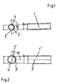
- FIGS. 1 and 2 each show an insulating tube 1 or 1 '. It consists of a round shaped strip material with two edges 3, 4, and 3 ', 4'. These edges do not abut one another, but overlap one another over a specific section 2, or 2 ', which is 180 ° in FIG. 1 and 90 ° in FIG. 2. It does not matter which side the other overlaps.
- the overlapping sections 2, or 2 ' are produced by screwing a slotted tube or a flat material and at the same time thermally deforming it.
- the insulating hoses 1, 1 'shown here can be made in two different sizes. However, the drawing can also be read so that Fig. 1 is a standard size and Fig. 2 shows how the standard size is expanded by inserting corresponding or correspondingly many cables, so that the overlap area is reduced from 180 ° to 90 °.
- FIGS. 3 and 4 basically represent the same situation as FIGS. 1 and 2.
- the insulating tube is spirally screwed in here, as shown by the course of the edge 3 ", 3". This design ensures a particularly high stability and an overall better buckling behavior.
Landscapes
- Engineering & Computer Science (AREA)
- Architecture (AREA)
- Civil Engineering (AREA)
- Structural Engineering (AREA)
- Insulating Bodies (AREA)
- Insulators (AREA)
- Coupling Device And Connection With Printed Circuit (AREA)
- Cable Accessories (AREA)
Description
- Die vorliegende Erfindung betrifft einen Isolierschlauch mit Schlitz.
- Es ist bekannt, Isolierschläuche aus einem thermoplastischen Material herzustellen, die zur leichtern Handhabung einen Längsschlitz aufweisen, da so Kabel oder Leitungen, bzw. Adern an beliebigen Stellen von der Seite her eingeführt werden können. Da bei solchen Längsschlitzen die Kabel/Leitungen durch den Schlitz heraustreten können, werden die Schläuche häufig umwickelt. Dies erfordert zusätzlichen Arbeitsaufwand.
-
EP 0 889 566 A1 offenbart einen Isolierschlauch aus Polyethylen mit einem durchgehenden Längsschlitz, wobei die Kanten des Schlitzes sich überlappen. - Aufgabe der vorliegenden Erfindung ist es, einen Isolierschlauch mit Schlitz zu schaffen, der ohne zusätzliche Umwicklung das Austreten von Kabeln/Leitungen verhindert und die eigentliche Funktion, nämlich den Schutz der geführten Kabel/Leitungen vor Abrieb und mechanischer Beeinflussung sicherstellt.
- Diese Aufgabe wird mit den Merkmalen des kennzeichnenden Teils des Anspruchs 1 gelöst. Fortbildungen und vorteilhafte Ausführungen der Erfindung sind in den weiteren Ansprüchen umfasst.
- Erfindungsgemäß ist ein Isolierschlauch aus einem Kunststoffmaterial mit einem achsparallelen, durchgehenden Längsschlitz dadurch gekennzeichnet, dass der Isolierschlauch elastisch und formstabil ausgeführt ist und dass der Längsschlitz durch einen Abschnitt des Isolierschlauchs in einen Bereich von mindestens 30° bis zu 360° überlappt wird. Vorzugsweise weist der Überlappungsbereich eine konstante Breite auf.
- Im Überlappungsbereich sind Haftmittel zwischen der Unterseite des Überlappungsabschnitts und der Oberseite des Isolierschlauchs angeordnet. Die Haftmittel können selbsthaftend oder durch Druck haftend ausgeführt sein. Zum Beispiel bestehen die Haftmittel ein Klettverschluss sind oder anderweitig aus Haken, Krallen, Ösen oder Schlingen. Eine Alternative sind miteinander haftende Filz-, Gewirke- oder Gewebeschichten. Außerdem können die Haftmittel aus lösbaren Kleberschichten bestehen, wie sie von Notizzetteln grundsätzlich her bekannt sind.
- Vorteilhafterweise sind die Haftmittel wenigstens an einer Seite in einer Breite ausgeführt, dass verschiedene Durchmesser des Isolierschlauchs einstellbar sind. Dabei muss die Haltekraft der Haftmittel jedoch die elastische Rückstellkraft des thermoplastischen Kunststoffmaterials überwinden.
- Der Isolierschlauch kann aus einem geschlitzten, thermoplastisch verformten extrudierten Schlauch bestehen, jedoch auch aus einem thermoplastisch verformten Streifenmaterial. Im ersteren Fall wird der Isolierschlauch extrudiert, danach geschlitzt und auf den kleineren Durchmesser eingedreht Im zweiten Fall wird der Isolierschlauch aus einem Flachmaterial verformt. Nach einer bevorzugten Ausführung der Erfindung ist der Isolierschlauch spiralförmig eingedreht. Das verwendete thermoplastische Material ist vorzugsweise ein Polyurethan. Es können aber auch andere Materialien wie PVC, Polyethylen usw. verwendet werden.
- Im Folgenden wird die Erfindung anhand von Zeichnungen beispielhaft näher beschrieben. Dabei zeigen:
- Fig. 1 und Fig. 2 eine erste Ausführung eines Isolierschlauchs;
- Fig. 3 und 4 eine zweite Ausführung eines Isolierschlauchs.
- Fig. 1 und 2 zeigen jeweils einen Isolierschlauch 1, bzw. 1'. Er besteht aus einem rund geformten Streifenmaterial mit zwei Kanten 3, 4, bzw. 3', 4'. Diese Kanten stoßen nicht aneinander, sondern überlappen sich um einen bestimmten Abschnitt 2, bzw. 2', der bei Fig. 1 180° und bei Fig. 2 90° beträgt. Dabei ist unerheblich, welche Seite die andere überlappt. Die Überlappungsabschnitte 2, bzw. 2' werden hergestellt, indem ein geschlitzter Schlauch, bzw. ein Flachmaterial eingedreht und gleichzeitig thermisch verformt wird. Die hier dargestellten Isolierschläuche 1, 1' können in zwei verschiedenen Größen hergestellt sein. Die Zeichnung kann jedoch auch so gelesen werden, dass Fig. 1 eine Standardgröße ist und Fig. 2 darstellt, wie die Standardgröße durch Einlegen entsprechender oder entsprechend vieler Kabel aufgedehnt wird, so dass der Überlappungsbereich von 180° auf 90° reduziert wird.
- Fig. 3 und 4 stellen grundsätzlich die gleiche Situation wie Fig. 1 und 2 dar. Jedoch ist der Isolierschlauch hier spiralförmig eingedreht, was durch den Verlauf der Kante 3", 3" gezeigt ist. Diese Ausführung gewährleistet eine besonders große Stabilität und ein gesamt besseres Einknickverhalten.
Claims (10)
- Isolierschlauch (1, 1') aus einem thermoplastischen Kunststoffmaterial mit einem durchgehenden Längsschlitz,
dadurch gekennzeichnet,
dass der Isolierschlauch elastisch und formstabil ausgeführt ist, und dass der Längsschlitz durch einen Abschnitt (2, 2') des Isolierschlauchs in einen Bereich von mindestens 30° bis zu 360° lose überlappt wird und im Überlappungsbereich Haftmittel zwischen der Unterseite des Überlappungsbereichs und der Oberseite des Isolierschlauchs angeordnet sind. - Isolierschlauch nach Anspruch 1,
dadurch gekennzeichnet,
dass der Überlappungsbereich eine konstante Breite aufweist. - Isolierschlauch nach Anspruch 1,
dadurch gekennzeichnet,
dass die Haftmittel selbsthaftend oder durch Druck haftend ausgeführt sind. - Isolierschlauch nach Anspruch 1,
dadurch gekennzeichnet,
dass die Haftmittel ein Klettverschluss sind oder anderweitig aus Haken, Krallen, Ösen oder Schlingen bestehen. - Isolierschlauch nach Anspruch 1,
dadurch gekennzeichnet,
dass die Haftmittel aus miteinander haftenden Filz-, Gewirke- oder Gewebeschichten bestehen. - Isolierschlauch nach Anspruch 1,
dadurch gekennzeichnet,
dass die Haftmittel aus lösbaren Kleberschichten bestehen. - Isolierschlauch nach einem der Ansprüche 1 bis 6,
dadurch gekennzeichnet,
dass die Haftmittel wenigstens an einer Seite in einer Breite ausgeführt sind, dass verschiedene Durchmesser des Isolierschlauchs einstellbar sind. - Isolierschlauch nach einem der vorhergehenden Ansprüche,
dadurch gekennzeichnet,
dass der Isolierschlauch aus einem geschlitzten, thermoplastisch verformten extrudierten Schlauch besteht. - Isolierschlauch nach einem der Ansprüche 1 bis 7,
dadurch gekennzeichnet,
dass der Isolierschlauch aus einem thermoplastisch verformten Streifenmaterial besteht. - Isolierschlauch nach einem der vorhergehenden Ansprüche,
dadurch gekennzeichnet,
dass der Isolierschlauch spiralförmig eingedreht ist.
Priority Applications (1)
| Application Number | Priority Date | Filing Date | Title |
|---|---|---|---|
| PL04011060T PL1494248T3 (pl) | 2003-05-09 | 2004-05-10 | Izolujący wąż ze szczeliną |
Applications Claiming Priority (2)
| Application Number | Priority Date | Filing Date | Title |
|---|---|---|---|
| DE20307300U | 2003-05-09 | ||
| DE20307300U DE20307300U1 (de) | 2003-05-09 | 2003-05-09 | Isolierschlauch mit Schlitz |
Publications (3)
| Publication Number | Publication Date |
|---|---|
| EP1494248A2 EP1494248A2 (de) | 2005-01-05 |
| EP1494248A3 EP1494248A3 (de) | 2005-02-02 |
| EP1494248B1 true EP1494248B1 (de) | 2007-07-11 |
Family
ID=28051467
Family Applications (1)
| Application Number | Title | Priority Date | Filing Date |
|---|---|---|---|
| EP04011060A Expired - Lifetime EP1494248B1 (de) | 2003-05-09 | 2004-05-10 | Isolierhülse mit Schlitz |
Country Status (5)
| Country | Link |
|---|---|
| EP (1) | EP1494248B1 (de) |
| AT (1) | ATE366987T1 (de) |
| DE (2) | DE20307300U1 (de) |
| ES (1) | ES2291771T3 (de) |
| PL (1) | PL1494248T3 (de) |
Families Citing this family (10)
| Publication number | Priority date | Publication date | Assignee | Title |
|---|---|---|---|---|
| DE102011086191A1 (de) * | 2011-09-01 | 2013-03-07 | Fränkische Industrial Pipes GmbH & Co. KG | Schutzschlauch |
| US10457033B2 (en) | 2016-11-07 | 2019-10-29 | The Boeing Company | Systems and methods for additively manufacturing composite parts |
| US11440261B2 (en) | 2016-11-08 | 2022-09-13 | The Boeing Company | Systems and methods for thermal control of additive manufacturing |
| US10759159B2 (en) * | 2017-05-31 | 2020-09-01 | The Boeing Company | Feedstock lines for additive manufacturing |
| US10814550B2 (en) | 2017-07-06 | 2020-10-27 | The Boeing Company | Methods for additive manufacturing |
| US10821672B2 (en) | 2017-07-06 | 2020-11-03 | The Boeing Company | Methods for additive manufacturing |
| US12409496B2 (en) | 2022-04-27 | 2025-09-09 | The Boeing Company | Pre-heating methods for performing electron beam powder bed fusion |
| US12485621B2 (en) | 2022-08-25 | 2025-12-02 | The Boeing Company | Methods of additively manufacturing a manufactured component and systems that perform the methods |
| US12343933B2 (en) | 2022-08-25 | 2025-07-01 | The Boeing Company | Methods of additively manufacturing a manufactured component and systems that perform the methods |
| DE202024101052U1 (de) | 2024-03-05 | 2024-03-26 | Gebauer & Griller Kabelwerke Gesellschaft M.B.H. | Vorrichtung zur Isolierung eines Kabels, Kabelstrangs oder Kabelbaums von Schwingungen |
Family Cites Families (3)
| Publication number | Priority date | Publication date | Assignee | Title |
|---|---|---|---|---|
| AU4937485A (en) * | 1984-11-05 | 1986-05-15 | Rheem Australia Pty Limited | Layered fabric |
| DE3927626A1 (de) * | 1989-08-22 | 1991-02-28 | Hoechst Ag | Schlauch aus polypropylen-schrumpffolie, verfahren zu seiner herstellung und seine verwendung |
| US20030029514A1 (en) * | 2001-08-10 | 2003-02-13 | Winzeler Michael D. | Flexible hose |
-
2003
- 2003-05-09 DE DE20307300U patent/DE20307300U1/de not_active Expired - Lifetime
-
2004
- 2004-05-10 AT AT04011060T patent/ATE366987T1/de not_active IP Right Cessation
- 2004-05-10 PL PL04011060T patent/PL1494248T3/pl unknown
- 2004-05-10 ES ES04011060T patent/ES2291771T3/es not_active Expired - Lifetime
- 2004-05-10 EP EP04011060A patent/EP1494248B1/de not_active Expired - Lifetime
- 2004-05-10 DE DE502004004275T patent/DE502004004275D1/de not_active Expired - Fee Related
Also Published As
| Publication number | Publication date |
|---|---|
| ATE366987T1 (de) | 2007-08-15 |
| DE20307300U1 (de) | 2003-09-11 |
| DE502004004275D1 (de) | 2007-08-23 |
| PL1494248T3 (pl) | 2008-02-29 |
| EP1494248A2 (de) | 2005-01-05 |
| EP1494248A3 (de) | 2005-02-02 |
| ES2291771T3 (es) | 2008-03-01 |
Similar Documents
| Publication | Publication Date | Title |
|---|---|---|
| DE60029848T2 (de) | Verfahren und Vorrichtung zum Unterteilen eines Kanals in Kammern | |
| EP3197968B1 (de) | Verfahren zur herstellung einer ummantelung für langgestrecktes gut | |
| EP1494248B1 (de) | Isolierhülse mit Schlitz | |
| DE10159277A1 (de) | Halter mit beweglichem Bogen | |
| DE112018001913B4 (de) | Verbindungsvorrichtung, Clippatrize, Sitzbezug und Sitz | |
| EP3180405B1 (de) | Verfahren zur herstellung einer ummantelung für langgestrecktes gut | |
| DE112018007359B4 (de) | Kabelbaum mit Befestigungselement | |
| EP0068128A1 (de) | Aus Bandmaterial gewickelter, durch Drahtwendel verstärkter flexibler Schlauch | |
| DE112016002742T5 (de) | Spule aus Papier | |
| WO2015052022A1 (de) | Umhüllungsmittel für ein langgestrecktes gut und dessen verwendung | |
| DE19641421A1 (de) | Wellrohr zur schützenden Ummantelung elektrischer Leitungen | |
| AT396533B (de) | Rohraggregat aus einer mehrzahl von kunststoffrohren | |
| EP2104970A1 (de) | Anordnung zum konfektionieren von schutzschläuchen mit darin eingebrachten kabeln, leitungen, und dergleichen | |
| DE19927958A1 (de) | Verfahren zur Herstellung eines Wellrohres mit einer längs einer Matellinie verlaufenden schlitzförmigen Öffnung | |
| DE1590543A1 (de) | Verfahren zur Herstellung eines luftraumisolierten Koaxialkabels | |
| AT522590B1 (de) | Rohr- und Leitungsdurchführung und Verfahren zur Montage | |
| DE102007014076A1 (de) | Anschluss- oder Abschlussband für Gebäude mit Sollknickstelle | |
| EP2067731A2 (de) | Aufwickelrohr oder Aufwickellhülse für Materialbahnen | |
| DE3231236C2 (de) | Kabelschelle | |
| DE606311C (de) | Gummischlauch mit eingelegten Fadenschichten | |
| DE102014114794A1 (de) | Verfahren zur Herstellung einer Ummantelung für langgestrecktes Gut | |
| DE10356973B3 (de) | Schutzummantelung für Kabelbäume von Kraftfahrzeugen | |
| EP0808592A2 (de) | Rollbare Isoliermatte | |
| AT399548B (de) | Mehrfachrohr | |
| DE102024125521A1 (de) | Laminiertes leitfähiges Stoffband |
Legal Events
| Date | Code | Title | Description |
|---|---|---|---|
| PUAI | Public reference made under article 153(3) epc to a published international application that has entered the european phase |
Free format text: ORIGINAL CODE: 0009012 |
|
| PUAL | Search report despatched |
Free format text: ORIGINAL CODE: 0009013 |
|
| AK | Designated contracting states |
Kind code of ref document: A2 Designated state(s): AT BE BG CH CY CZ DE DK EE ES FI FR GB GR HU IE IT LI LU MC NL PL PT RO SE SI SK TR |
|
| AX | Request for extension of the european patent |
Extension state: AL HR LT LV MK |
|
| AK | Designated contracting states |
Kind code of ref document: A3 Designated state(s): AT BE BG CH CY CZ DE DK EE ES FI FR GB GR HU IE IT LI LU MC NL PL PT RO SE SI SK TR |
|
| AX | Request for extension of the european patent |
Extension state: AL HR LT LV MK |
|
| RIC1 | Information provided on ipc code assigned before grant |
Ipc: 7H 01B 7/02 B Ipc: 7F 16L 11/04 B Ipc: 7H 01B 3/30 A |
|
| 17P | Request for examination filed |
Effective date: 20050802 |
|
| AKX | Designation fees paid |
Designated state(s): AT BE BG CH CY CZ DE DK EE ES FI FR GB GR HU IE IT LI LU MC NL PL PT RO SE SI SK TR |
|
| 17Q | First examination report despatched |
Effective date: 20060523 |
|
| GRAP | Despatch of communication of intention to grant a patent |
Free format text: ORIGINAL CODE: EPIDOSNIGR1 |
|
| GRAS | Grant fee paid |
Free format text: ORIGINAL CODE: EPIDOSNIGR3 |
|
| GRAA | (expected) grant |
Free format text: ORIGINAL CODE: 0009210 |
|
| AK | Designated contracting states |
Kind code of ref document: B1 Designated state(s): AT BE BG CH CY CZ DE DK EE ES FI FR GB GR HU IE IT LI LU MC NL PL PT RO SE SI SK TR |
|
| REG | Reference to a national code |
Ref country code: GB Ref legal event code: FG4D Free format text: NOT ENGLISH |
|
| REG | Reference to a national code |
Ref country code: CH Ref legal event code: EP |
|
| REF | Corresponds to: |
Ref document number: 502004004275 Country of ref document: DE Date of ref document: 20070823 Kind code of ref document: P |
|
| REG | Reference to a national code |
Ref country code: IE Ref legal event code: FG4D Free format text: LANGUAGE OF EP DOCUMENT: GERMAN |
|
| REG | Reference to a national code |
Ref country code: RO Ref legal event code: EPE |
|
| GBT | Gb: translation of ep patent filed (gb section 77(6)(a)/1977) |
Effective date: 20071212 |
|
| ET | Fr: translation filed | ||
| PG25 | Lapsed in a contracting state [announced via postgrant information from national office to epo] |
Ref country code: PT Free format text: LAPSE BECAUSE OF FAILURE TO SUBMIT A TRANSLATION OF THE DESCRIPTION OR TO PAY THE FEE WITHIN THE PRESCRIBED TIME-LIMIT Effective date: 20071211 Ref country code: NL Free format text: LAPSE BECAUSE OF FAILURE TO SUBMIT A TRANSLATION OF THE DESCRIPTION OR TO PAY THE FEE WITHIN THE PRESCRIBED TIME-LIMIT Effective date: 20070711 Ref country code: FI Free format text: LAPSE BECAUSE OF FAILURE TO SUBMIT A TRANSLATION OF THE DESCRIPTION OR TO PAY THE FEE WITHIN THE PRESCRIBED TIME-LIMIT Effective date: 20070711 |
|
| NLV1 | Nl: lapsed or annulled due to failure to fulfill the requirements of art. 29p and 29m of the patents act | ||
| REG | Reference to a national code |
Ref country code: HU Ref legal event code: AG4A Ref document number: E002323 Country of ref document: HU |
|
| REG | Reference to a national code |
Ref country code: PL Ref legal event code: T3 |
|
| REG | Reference to a national code |
Ref country code: ES Ref legal event code: FG2A Ref document number: 2291771 Country of ref document: ES Kind code of ref document: T3 |
|
| REG | Reference to a national code |
Ref country code: IE Ref legal event code: FD4D |
|
| PG25 | Lapsed in a contracting state [announced via postgrant information from national office to epo] |
Ref country code: GR Free format text: LAPSE BECAUSE OF FAILURE TO SUBMIT A TRANSLATION OF THE DESCRIPTION OR TO PAY THE FEE WITHIN THE PRESCRIBED TIME-LIMIT Effective date: 20071012 Ref country code: DK Free format text: LAPSE BECAUSE OF FAILURE TO SUBMIT A TRANSLATION OF THE DESCRIPTION OR TO PAY THE FEE WITHIN THE PRESCRIBED TIME-LIMIT Effective date: 20070711 |
|
| PLBE | No opposition filed within time limit |
Free format text: ORIGINAL CODE: 0009261 |
|
| STAA | Information on the status of an ep patent application or granted ep patent |
Free format text: STATUS: NO OPPOSITION FILED WITHIN TIME LIMIT |
|
| PG25 | Lapsed in a contracting state [announced via postgrant information from national office to epo] |
Ref country code: IE Free format text: LAPSE BECAUSE OF FAILURE TO SUBMIT A TRANSLATION OF THE DESCRIPTION OR TO PAY THE FEE WITHIN THE PRESCRIBED TIME-LIMIT Effective date: 20070711 |
|
| 26N | No opposition filed |
Effective date: 20080414 |
|
| PG25 | Lapsed in a contracting state [announced via postgrant information from national office to epo] |
Ref country code: SE Free format text: LAPSE BECAUSE OF FAILURE TO SUBMIT A TRANSLATION OF THE DESCRIPTION OR TO PAY THE FEE WITHIN THE PRESCRIBED TIME-LIMIT Effective date: 20071011 |
|
| BERE | Be: lapsed |
Owner name: UNIWELL WELLROHR G.M.B.H. Effective date: 20080531 |
|
| PG25 | Lapsed in a contracting state [announced via postgrant information from national office to epo] |
Ref country code: MC Free format text: LAPSE BECAUSE OF NON-PAYMENT OF DUE FEES Effective date: 20080531 |
|
| PG25 | Lapsed in a contracting state [announced via postgrant information from national office to epo] |
Ref country code: EE Free format text: LAPSE BECAUSE OF FAILURE TO SUBMIT A TRANSLATION OF THE DESCRIPTION OR TO PAY THE FEE WITHIN THE PRESCRIBED TIME-LIMIT Effective date: 20070711 |
|
| PG25 | Lapsed in a contracting state [announced via postgrant information from national office to epo] |
Ref country code: BE Free format text: LAPSE BECAUSE OF NON-PAYMENT OF DUE FEES Effective date: 20080531 |
|
| PG25 | Lapsed in a contracting state [announced via postgrant information from national office to epo] |
Ref country code: SI Free format text: LAPSE BECAUSE OF FAILURE TO SUBMIT A TRANSLATION OF THE DESCRIPTION OR TO PAY THE FEE WITHIN THE PRESCRIBED TIME-LIMIT Effective date: 20070711 |
|
| PG25 | Lapsed in a contracting state [announced via postgrant information from national office to epo] |
Ref country code: CY Free format text: LAPSE BECAUSE OF FAILURE TO SUBMIT A TRANSLATION OF THE DESCRIPTION OR TO PAY THE FEE WITHIN THE PRESCRIBED TIME-LIMIT Effective date: 20070711 |
|
| PGFP | Annual fee paid to national office [announced via postgrant information from national office to epo] |
Ref country code: BG Payment date: 20090526 Year of fee payment: 6 Ref country code: ES Payment date: 20090521 Year of fee payment: 6 Ref country code: RO Payment date: 20090505 Year of fee payment: 6 |
|
| PGFP | Annual fee paid to national office [announced via postgrant information from national office to epo] |
Ref country code: AT Payment date: 20090515 Year of fee payment: 6 Ref country code: CZ Payment date: 20090430 Year of fee payment: 6 Ref country code: FR Payment date: 20090513 Year of fee payment: 6 Ref country code: PL Payment date: 20090505 Year of fee payment: 6 |
|
| PGFP | Annual fee paid to national office [announced via postgrant information from national office to epo] |
Ref country code: SK Payment date: 20090507 Year of fee payment: 6 |
|
| PGFP | Annual fee paid to national office [announced via postgrant information from national office to epo] |
Ref country code: CH Payment date: 20090518 Year of fee payment: 6 |
|
| PGFP | Annual fee paid to national office [announced via postgrant information from national office to epo] |
Ref country code: DE Payment date: 20090728 Year of fee payment: 6 Ref country code: GB Payment date: 20090507 Year of fee payment: 6 Ref country code: HU Payment date: 20090513 Year of fee payment: 6 |
|
| PG25 | Lapsed in a contracting state [announced via postgrant information from national office to epo] |
Ref country code: LU Free format text: LAPSE BECAUSE OF NON-PAYMENT OF DUE FEES Effective date: 20080510 |
|
| PG25 | Lapsed in a contracting state [announced via postgrant information from national office to epo] |
Ref country code: TR Free format text: LAPSE BECAUSE OF FAILURE TO SUBMIT A TRANSLATION OF THE DESCRIPTION OR TO PAY THE FEE WITHIN THE PRESCRIBED TIME-LIMIT Effective date: 20070711 |
|
| REG | Reference to a national code |
Ref country code: CH Ref legal event code: PL |
|
| GBPC | Gb: european patent ceased through non-payment of renewal fee |
Effective date: 20100510 |
|
| PG25 | Lapsed in a contracting state [announced via postgrant information from national office to epo] |
Ref country code: AT Free format text: LAPSE BECAUSE OF NON-PAYMENT OF DUE FEES Effective date: 20100510 |
|
| REG | Reference to a national code |
Ref country code: SK Ref legal event code: MM4A Ref document number: E 2488 Country of ref document: SK Effective date: 20100510 |
|
| REG | Reference to a national code |
Ref country code: FR Ref legal event code: ST Effective date: 20110131 |
|
| PG25 | Lapsed in a contracting state [announced via postgrant information from national office to epo] |
Ref country code: HU Free format text: LAPSE BECAUSE OF NON-PAYMENT OF DUE FEES Effective date: 20100511 Ref country code: CZ Free format text: LAPSE BECAUSE OF NON-PAYMENT OF DUE FEES Effective date: 20100510 Ref country code: IT Free format text: LAPSE BECAUSE OF NON-PAYMENT OF DUE FEES Effective date: 20080531 Ref country code: CH Free format text: LAPSE BECAUSE OF NON-PAYMENT OF DUE FEES Effective date: 20100531 Ref country code: BG Free format text: LAPSE BECAUSE OF NON-PAYMENT OF DUE FEES Effective date: 20101230 Ref country code: SK Free format text: LAPSE BECAUSE OF NON-PAYMENT OF DUE FEES Effective date: 20100510 Ref country code: LI Free format text: LAPSE BECAUSE OF NON-PAYMENT OF DUE FEES Effective date: 20100531 |
|
| PG25 | Lapsed in a contracting state [announced via postgrant information from national office to epo] |
Ref country code: DE Free format text: LAPSE BECAUSE OF NON-PAYMENT OF DUE FEES Effective date: 20101201 |
|
| PG25 | Lapsed in a contracting state [announced via postgrant information from national office to epo] |
Ref country code: FR Free format text: LAPSE BECAUSE OF NON-PAYMENT OF DUE FEES Effective date: 20100531 Ref country code: RO Free format text: LAPSE BECAUSE OF NON-PAYMENT OF DUE FEES Effective date: 20100510 |
|
| REG | Reference to a national code |
Ref country code: ES Ref legal event code: FD2A Effective date: 20110711 |
|
| PG25 | Lapsed in a contracting state [announced via postgrant information from national office to epo] |
Ref country code: ES Free format text: LAPSE BECAUSE OF NON-PAYMENT OF DUE FEES Effective date: 20110629 Ref country code: GB Free format text: LAPSE BECAUSE OF NON-PAYMENT OF DUE FEES Effective date: 20100510 |
|
| PG25 | Lapsed in a contracting state [announced via postgrant information from national office to epo] |
Ref country code: ES Free format text: LAPSE BECAUSE OF NON-PAYMENT OF DUE FEES Effective date: 20100511 |
|
| REG | Reference to a national code |
Ref country code: PL Ref legal event code: LAPE |
|
| PG25 | Lapsed in a contracting state [announced via postgrant information from national office to epo] |
Ref country code: PL Free format text: LAPSE BECAUSE OF NON-PAYMENT OF DUE FEES Effective date: 20100510 |