EP1494496A1 - Mobiles Kommunikationssystem und dazugehöriges Kommunikationssteuerverfahren - Google Patents
Mobiles Kommunikationssystem und dazugehöriges Kommunikationssteuerverfahren Download PDFInfo
- Publication number
- EP1494496A1 EP1494496A1 EP04015420A EP04015420A EP1494496A1 EP 1494496 A1 EP1494496 A1 EP 1494496A1 EP 04015420 A EP04015420 A EP 04015420A EP 04015420 A EP04015420 A EP 04015420A EP 1494496 A1 EP1494496 A1 EP 1494496A1
- Authority
- EP
- European Patent Office
- Prior art keywords
- radio device
- radio
- last
- base station
- mobile unit
- Prior art date
- Legal status (The legal status is an assumption and is not a legal conclusion. Google has not performed a legal analysis and makes no representation as to the accuracy of the status listed.)
- Granted
Links
- 238000004891 communication Methods 0.000 title claims abstract description 220
- 238000010295 mobile communication Methods 0.000 title claims abstract description 55
- 238000000034 method Methods 0.000 title claims description 34
- 238000009434 installation Methods 0.000 claims description 37
- 238000005259 measurement Methods 0.000 claims description 5
- 238000010586 diagram Methods 0.000 description 18
- 238000012545 processing Methods 0.000 description 5
- 238000010276 construction Methods 0.000 description 4
- 230000002349 favourable effect Effects 0.000 description 3
- 239000000470 constituent Substances 0.000 description 1
- 238000012986 modification Methods 0.000 description 1
- 230000004048 modification Effects 0.000 description 1
- 238000002360 preparation method Methods 0.000 description 1
- 230000000717 retained effect Effects 0.000 description 1
Images





Classifications
-
- H—ELECTRICITY
- H04—ELECTRIC COMMUNICATION TECHNIQUE
- H04W—WIRELESS COMMUNICATION NETWORKS
- H04W88/00—Devices specially adapted for wireless communication networks, e.g. terminals, base stations or access point devices
- H04W88/18—Service support devices; Network management devices
-
- H—ELECTRICITY
- H04—ELECTRIC COMMUNICATION TECHNIQUE
- H04W—WIRELESS COMMUNICATION NETWORKS
- H04W16/00—Network planning, e.g. coverage or traffic planning tools; Network deployment, e.g. resource partitioning or cells structures
-
- H—ELECTRICITY
- H04—ELECTRIC COMMUNICATION TECHNIQUE
- H04W—WIRELESS COMMUNICATION NETWORKS
- H04W4/00—Services specially adapted for wireless communication networks; Facilities therefor
- H04W4/30—Services specially adapted for particular environments, situations or purposes
- H04W4/40—Services specially adapted for particular environments, situations or purposes for vehicles, e.g. vehicle-to-pedestrians [V2P]
- H04W4/42—Services specially adapted for particular environments, situations or purposes for vehicles, e.g. vehicle-to-pedestrians [V2P] for mass transport vehicles, e.g. buses, trains or aircraft
-
- H—ELECTRICITY
- H04—ELECTRIC COMMUNICATION TECHNIQUE
- H04W—WIRELESS COMMUNICATION NETWORKS
- H04W84/00—Network topologies
Definitions
- the present invention relates to a mobile communication system and a communication control method for use with the system including cells of which each defines a predetermined radio wave arrival range of radio waves from a fixed base station associated with the cell, and in particular, to a mobile communication system and a communication control method for use with the system suitable for a mobile unit or module such as a train moving at a high speed.
- Japanese Patent Laid-Open No. Hei11-298967 filed before the present specification describes a technique in which a wireless mobile station which can be connected to a public communication line and/or a leased communication line to communicate with an outer-vehicle wireless base station disposed outside a vehicle and an inner-vehicle wireless base station to communicate with the mobile station and a wireless terminal device in a vehicle are arranged so that signals are transmitted from the vehicle to the outer-vehicle base station.
- Japanese Patent Laid-Open Ser. No. 09-327057 proposes a mobile communication system in which to enable communication in a running train by use of a mobile terminal device (PS) for a micro-cell system, there are disposed a plurality of inside wireless stations (CS) in a train for a micro-cell system to communicate with the mobile terminal so that a wireless base station (BS) disposed outside of the train is connected to the inside stations (CS).
- PS mobile terminal device
- CS inside wireless stations
- BS wireless base station
- Japanese Patent Laid-Open No. Hei-10-164640 describes a mobile communication system in which a communicating device to communicate with a mobile terminal in a mobile unit is arranged in a place of a first end thereof and in a place of a last end thereof.
- the communicating devices at the first and last ends of the mobile unit conduct a change-over operation with respect to an external fixed base station to continuously retain a linked state in which each of the communicating devices establishes a link with the fixed base station.
- cells are adjacent to each other or overlap with each other to continuously use a communication line between a mobile wireless device and a fixed wireless station.
- a mobile wireless device 100 in a linked state for a fixed wireless base station A namely, in a state capable of communicating with the base station A moves in a running direction to a position outside a cell a configured by the base station A
- the device 100 enters a non-linked or disconnected state for the base station A, i.e., a state in which the device 100 cannot communicate with the base station A. That is, the link between the wireless device 100 and the base station A is disconnected and hence communication is not possible therebetween.
- the system is configured so that the cell a of the base station A is contiguous to a cell b constructed by a fixed wireless base station B or the cell a overlaps with the cell b as shown in Fig. 17. Thanks to this configuration, the link between the mobile device 100 and the base station A is released and a new link is prepared between the device 100 and the base station B in the situation described above. As a result, the communication line being used by the wireless terminal device 100 is kept connected.
- the cells (a and b) are adjacent to each other or overlap with each other in consideration of each size of a radio signal receivable range of each fixed wireless base station and a distance between the base stations. That is, the cells are configured only according to the fixed base stations. To reduce the number of base stations in this case, it is favorable to separate the cells (a and b) from each other as shown in Fig. 18. However, in accordance with Japanese Patent Laid-Open Nos.
- the technique has an object in which the first and second mobile communication units are alternately set to the linked state, namely, either one there of is in the communicable state to continuously carry out communication when the cells overlap with each other.
- a switching section releases the linked state of the other one thereof into a non-linked state so that only one of the communication units is in the linked state. This complicates control processing of the switching section and hence there exits a fear of delay in the switching operation to establish a linked state in the mobile communication unit.
- a mobile communication system including a plurality of fixed radio base stations each of which configures a predetermined wave arrival range and establishes a linked state with a radio device within the wave arrival range to conduct radio communication with the radio device, and a mobile unit with at least two modules of the radio devices mounted at positions of the mobile unit to be in a wave arrival range of any one of the base stations, the unit including a communication control unit for controlling the radio devices on the mobile unit.
- the base stations are disposed at positions at which the base stations form wave arrival ranges not overlapping with each other.
- the communication control unit includes a radio device connecting module for establishing a communication network between a plurality of mobile terminals in the mobile unit and at least one radio device selected from a first-end radio device mounted in a first-end section of the mobile unit and linked in a linked state with one of the base stations and a last-end radio device mounted in a last-end section of the mobile unit and linked in a linked state with one of the base stations.
- the radio device connecting module establishes a communication network between the first-end radio device and the mobile terminals at occurrence of an event in which the linked state of the first-end radio device with a first fixed radio base station is once released and then a linked state of the first-end radio device with a second fixed radio base station is established.
- the radio device connecting module establishes a communication network between the last-end radio device and the mobile terminals at occurrence of an event in which the linked state of the last-end radio device with the first fixed radio base station is once released and then a linked state of the last-end radio device with the second fixed radio base station is established.
- the communication control unit includes a radio wave control module for comparing a value of a radio wave level received by the first-end radio device from the base station associated therewith with a value of a radio wave level received by the last-end radio device from the base station associated therewith.
- the radio device connecting module establishes a communication network between the mobile terminals in the mobile unit and one of the radio devices having a higher value of the radio wave level determined as a result of the comparison by the radio wave control module.
- the radio wave control module compares, when a radio wave received by the first-end radio device from the base station associated therewith is transmitted from the first-end radio device or when a radio wave received by the last-end radio device from the base station associated therewith is transmitted from the last-end radio device, values of radio wave levels of the radio waves with each other, and establishes a communication network between the mobile terminals in the mobile unit and one of the radio devices having a higher value of the radio wave level determined as a result of the comparison by the radio wave control module.
- the first-end radio device measures therein a value of a level of a radio wave received by the first-end radio device from the base station associated therewith and the last-end radio device measures therein a value of a level of a radio wave received by the last-end radio device from the base station associated therewith.
- the radio wave control module compares, when the values resultant from measurement by the respective radio devices are transmitted therefrom, the values with each other and then establishes a communication network between the mobile terminals in the mobile unit and one of the radio devices having a higher value of the radio wave level determined as a result of the comparison by the radio wave control module.
- the communication control unit includes a positional information measuring module for measuring a central position of the mobile unit while the mobile unit is moving, a positional information storage module for storing installation positions respectively of the fixed radio base stations, and a positional information retrieval module for retrieving from the positional information storage means an installation position of one of the base stations according to the central position of the mobile unit measured by the positional information measuring module, the installation position being most associated with the central position.
- the radio device connecting module establishes a communication network between the first-end radio device and the mobile terminals when it is determined that the installation position of the base station retrieved by the positional information retrieval module is at a forward position of the mobile unit.
- the radio device connecting module establishes a communication network between the last-end radio device and the mobile terminals when it is determined that the installation position of the base station retrieved by the positional information retrieval module is at a backward position of the mobile unit.
- the communication control unit includes a passage time calculating module for obtaining a period of incoming time from when the first-end radio device enters a radio wave arrival range formed by the base station associated therewith to when a central radio device disposed at a central position of the mobile unit enters the radio wave arrival range and a period of outgoing time from when the first-end radio device leaves the radio wave arrival range formed by the base station to when the central radio device leaves the radio wave arrival range.
- the radio device connecting module establishes a communication network between the last-end radio device and the mobile terminals by predicting, on the basis of the period of incoming time obtained by the passage time calculating module, a period of time from when the central radio device enters the radio wave arrival range to when the last-end radio device enters the radio wave arrival range.
- the radio device connecting module establishes a communication network between the first-end radio device and the mobile terminals by predicting, on the basis of the period of outgoing time obtained by the passage time calculating module, a period of time from when the central radio device leaves the radio wave arrival range to when the last-end radio device leaves the radio wave arrival range.
- the radio device connecting module establishes a communication network between the last-end radio device and the mobile terminals and a communication network between the first-end radio device and the mobile terminals when the last-end radio device is in the linked state with the first base station and the last-end radio device is in the linked state with the second base station.
- the communication control unit includes a communication data distributor module for making, when the radio device connecting module establishes a communication network between the last-end radio device and the mobile terminals and a communication network between the first-end radio device and the mobile terminals, a check to determine whether data is transmitted to the first-end radio device or the last-end radio device and sends a data packet to the first-end or last-end radio device determined as a result of the check.
- a communication control method for use with a mobile communication system comprising a plurality of fixed radio base stations each of which configures a predetermined wave arrival range and establishes a linked state with a radio device within the wave arrival range to conduct radio communication with the radio device and a mobile unit with at least two modules of the radio devices mounted at positions of the mobile unit to be in a wave arrival range of any one of the base stations, the unit including communication control unit for controlling the radio devices on the mobile unit, the communication control unit including a radio device connecting module for establishing a communication network between a plurality of mobile terminals in the mobile unit and at least one radio device selected from a first-end radio device mounted in a first-end section of the mobile unit and linked in a linked state with one of the base stations and a last-end radio device mounted in a last-end section of the mobile unit and linked in a linked state with one of the base stations.
- the method includes the steps of selecting by the radio device connecting module, when the radio device connecting module senses occurrence of an event in which the linked state of the first-end radio device with a first fixed radio base station is once released and then a linked state of the first-end radio device with a second fixed radio base station is established, the first-end radio.
- the radio device connecting module selects by the radio device connecting module, when the radio device connecting module senses occurrence of an event in which the linked state of the last-end radio device with the first fixed radio base station is once released and then a linked state of the last-end radio device with the second fixed radio base station is established, the last-end radio device and establishing a communication network between the last-end radio device and the mobile terminals.
- the communication control unit further includes a radio wave control module for comparing a value of a radio wave level received by the first-end radio device from the base station associated therewith with a value of a radio wave level received by the last-end radio device from the base station associated therewith.
- the method further includes the steps of comparing by the radio wave control module a value of a radio wave level received by the first-end radio device from the base station associated therewith with a value of a radio wave level received by the last-end radio device from the base station associated therewith, and establishing by the radio device connecting module a communication network between the mobile terminals in the mobile unit and one of the radio devices having a higher value of the radio wave level determined as a result of the comparison by the radio wave control module.
- the communication control method further includes the steps of comparing by the radio wave control module, when a radio wave received by the first-end radio device from the base station associated therewith is transmitted from the first-end radio device or when a radio wave received by the last-end radio device from the base station associated therewith is transmitted from the last-end radio device, values of radio wave levels of the radio waves with each other, and establishing by the radio device connecting module a communication network between the mobile terminals in the mobile unit and one of the radio devices having a higher value of the radio wave level determined as a result of the comparison by the radio wave control module.
- the communication control method further includes the steps of measuring by the first-end radio device a value of a level of a radio wave received from the base station associated therewith and transmitting the value to the radio wave control module, measuring by the last-end radio device a value of a level of a radio wave received from the base station associated therewith and transmitting the value to the radio wave control module, comparing by the radio wave control module, when the values resultant from measurement by the respective radio devices are transmitted therefrom, the values with each other, and establishing the radio device connecting module a communication network between the mobile terminals in the mobile unit and one of the radio devices having a higher value of the radio wave level determined as a result of the comparison by the radio wave control module.
- the communication control unit further includes a positional information measuring module for measuring a central position of the mobile unit while the mobile unit is moving, a positional information storage module for storing installation positions respectively of the fixed radio base stations, and a positional information retrieval module for retrieving from the positional information storage module an installation position of one of the base stations according to the central position of the mobile unit measured by the positional information measuring module, the installation position being most associated with the central position.
- the method further includes the steps of measuring by the positional information measuring module a central position of the mobile unit while the mobile unit is moving, and transmitting the central position to the positional information retrieval module; retrieving, by the positional information retrieval module, from the positional information storage module an installation position of one of the base stations according to the central position of the mobile unit measured by the positional information measuring module, the installation position being most associated with the central position, and delivering the installation position to the radio device connecting module; and establishing by the radio device connecting module a communication network between the first-end radio device and the mobile terminals when it is determined that the installation position of the base station retrieved by the positional information retrieval module is at a forward position of the mobile unit, and establishing a communication network between the last-end radio device and the mobile terminals when it is determined that the installation position of the base station retrieved by the positional information retrieval module is at a backward position of the mobile unit.
- the communication control unit further includes a passage time calculating module for obtaining a period of incoming time from when the first-end radio device enters a radio wave arrival range formed by the base station associated therewith to when a central radio device disposed at a central position of the mobile unit enters the radio wave arrival range and a period of outgoing time from when the first-end radio device leaves the radio wave arrival range formed by the base station to when the central radio device leaves the radio wave arrival range.
- the method further includes the steps of obtaining by the passage time calculating module the period of incoming time from when the first-end radio device enters a radio wave arrival range formed by the base station associated therewith to when a central radio device disposed at a central position of the mobile unit enters the radio wave arrival range, and transmitting the period of incoming time to the radio device connecting module; establishing by the radio device connecting module a communication network between the last-end radio device and the mobile terminals by predicting, on the basis of the period of incoming time obtained by the passage time calculating module, a period of time from when the central radio device enters the radio wave arrival range to when the last-end radio device enters the radio wave arrival range; obtaining by the passage time calculating module the period of outgoing time from when the first-end radio device leaves the radio wave arrival range formed by the base station to when the central radio device leaves the radio wave arrival range, and transmitting the period o outgoing time to the radio device connecting module; and establishing by the radio device connecting module a communication network between the first-end radio device and
- the communication control method further includes the step of establishing by the radio device connecting module a communication network between the last-end radio device and the mobile terminals and a communication network between the first-end radio device and the mobile terminals when the last-end radio device is in the linked state with the first base station and the last-end radio device is in the linked state with the second base station.
- the communication control unit further includes a communication data distributor module for making a check to determine whether data is transmitted to the first-end radio device or the last-end radio device and sends a data packet to the first-end or last-end radio device determined as a result of the check.
- the method further includes the steps of making a check by the communication data distributor module, when the radio device connecting module establishes a communication network between the last-end radio device and the mobile terminals and a communication network between the first-end radio device and the mobile terminals, to determine whether data is transmitted to the first-end radio device or the last-end radio device and sending a data packet to the first-end or last-end radio device determined as a result of the check.
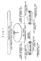
- the system includes fixed radio base stations 1-1 to 1-N (N is an integer more than one) and a mobile unit 2.
- the unit 2 includes wireless device 10 and 11 to conduct wireless or radio communication with the base stations 1-1 to 1-N.
- the base stations 1-1 to 1-N configure respective cells as ranges of arrival of a particular radio wave and communicate signals with the wireless devices 10 and 11 of the mobile unit 2 existing in such a cell.
- a link is set between the wireless devices 10 and 11 and the pertinent base station to conduct communication therebetween.
- the mobile unit 2 is, for example, a mobile unit having a predetermined length such as a train and moves between the cells of the base stations 1-1 to 1-N.
- a radio device i.e., a first-end radio unit 10 is disposed in a first-end section of the mobile unit 2 and a radio device, i.e., a last-end radio unit 11 is arranged in a last-end section of the unit 2 to communicate data with the base stations 1-1 to 1-N.
- the first-end and last-end radio units 10 and 11 alternately establish a link with one of the base stations 1-1 to 1-N to form a zone in which communication can be successively conducted.
- the configuration of the mobile unit 2 will now be described in detail by referring to Fig. 2.
- the wireless devices 10 and 11 are connected to a communication controller 20 controlling a communication network in the mobile unit 2.
- Each car of the train of the mobile unit 2 includes an inside communication unit 30.
- the controller 20 selects either one of wireless devices 10 and 11, the selected device conducts communication via the inside communication unit 30 with a mobile radio unit 40 disposed in the car.
- the unit 30 is a device to establish a communication network with the mobile radio unit 40 in the mobile unit 2.
- a network is established between the base stations 1-1 to 1-N and the mobile wireless devices 40 via the radio devices 10 and 11 and the inside communication device 30.
- the communication controller 20 of the first embodiment includes a communication path selecting section 21 and a communication processing section 22 to control a communication network between the inside communication unit 30 and the first-end radio unit 10 or the last-end radio unit 10. Description will next be given of functions of the controller 20 of the first embodiment.
- the communication path selector 21 selects connection between the wireless devices 10 and the communication processor 22 or between the wireless devices 11 and communication processor 22 to change a communication network to the mobile unit 2.
- the wireless device 10 or 11 When the wireless device 10 or 11 is disconnected from one of the base stations 1-1 to 1-N or is connected thereto, the wireless device 10 or 11 notifies the condition to the selector 21. Then, the selector 21 accomplishes the switching operation as described above.
- the communication processor 22 connects the communication network selected and set by the path selector 21 to the inside communication unit 30 of each car of the mobile unit 2. Resultantly, the processor 22 configures a communication network from the mobile radio unit 40 of each car via the inside communication unit 30 to the wireless device 10 or a communication network between the mobile radio unit 40 and the wireless device 11.
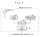
- Each of the wireless units 10 and 11 includes a controller 10a, a radio section 10b, a communication processing section 10c, a network interface (NW I/F) section 10d, and an antenna 10e.
- a network is constructed in the mobile unit 2. Description will no be given of functions of the constituent components of the unit 10 or 11.
- the controller 10a controls overall operation in the wireless unit.
- the wireless section 10b transmits data signals from the base stations 1-1 to 1-N disposed outside the mobile unit via the antenna 10e to the communication processor 10c.
- the section 10b also delivers a data signal sent from the communication processor 10c via the antenna 10e to the associated base station.
- the communication processor 10c feeds data signals of the base station from the wireless section 10b via the interface 10d to the communication controller 20.
- the communication section 10c also transmits a data signal from the controller 20 via the interface 10d to the radio section 10b.
- the network interface 10d delivers a data signal from the communication processor 10c to the communication controller 20.
- the interface 10d also feeds a data signal from the controller 20 to the communication processor 10c.
- the first embodiment includes the first-end wireless device 10 in the first-end section of the mobile unit 2 and the last-end wireless device 11 in the last-end section of the mobile unit 2.
- the present invention is not restricted by the embodiment. It is also possible to configure a mobile unit 2 in which the radio units 10 and 11 are respectively disposed at least in the first-end and the last-end sections of the unit 2.
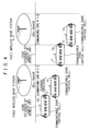
- the radio device 10 on the mobile unit 2 enters a cell formed by the first base station 1-1, the device 10 is linked with the base station 1-1.
- the path selecting section 21 of the communication controller 20 connects the radio device 10 to the communication processor 22 to set a linked state between the radio device 10 and the first base station 1-1 in the mobile unit 2.
- the mobile radio device 40 in the mobile unit 2 can communicate data with the base station 1-1 via the inside communication unit 30 in the train connected to the radio device 10.
- the device 11 is set to a linked state with respect to the base station 1-1. Resultantly, the radio devices 10 and 11 are linked with the base station 1-1.
- the path selector 21 of the controller 20 selects the linked state between the radio device 11 and the communication processor 22 and does not select the linked state between the radio device 10 and the processor 22. This forms only the linked state between the radio device 11 and the base station 1-1 in the mobile unit 2. Therefore, the mobile radio device 40 in the mobile unit 2 can conduct data communication with the base station 1-1 via the inside communication unit 30 in the train connected to the radio device 11.
- the mobile unit 2 further travels and leaves the cell of the base station 1-1 in the linked state with respect to the first-end radio device 10 on the mobile unit 2.
- the selector 21 of the controller 20 senses the event that the device 10 has left the cell of the base station 1-1.
- the selector 21 recognizes that the device 10 is going to enter a cell formed by the second base station 1-2 and prepares for a change to the connection between the device 10 and the communication processor 22.
- the mobile unit 2 proceeds in the running direction and the first-end radio device 10 thereof enters a cell of the second base station 1-2, the device 10 is linked with the base station 1-2.
- the selector 21 of the controller 20 changes the selection from the linked state between the radio device 11 and the communication processor 22 to that between the radio device 10 and the communication processor 22 to set only the linked state between the radio device 11 and the base station 1-2. Consequently, the mobile wireless module 40 in the mobile unit 2 can communicate data with the second base station 1-2 via the inside communication unit 30 in the train connected to the radio device 10.
- the moving unit 2 advances and the last-end radio device 11 thereon leaves the cell of the first base station 1-1 linked with the radio device 11.
- the selector 21 of the controller 20 detects the condition that the device 10 is out of the cell of the base station 1-1.
- the selector 21 recognizes that the device 10 is about to enter a cell of the second base station 1-2 and makes preparations for a change to the connection between the last-end wireless device 11 and the communication processor 22.
- the mobile unit 2 further travels and the last-end radio device 11 thereon enters a cell of the second base station 1-2, the device 11 is set to the linked state with the base station 1-2.
- the wireless devices 10 and 11 are linked with the base station 1-2 in this case.
- the path selector 21 of the communication controller 20 conducts a change-over operation from the connection between the radio device 10 and the communication processor 22 to that between the radio device 11 and the communication processor 22. This resultantly establishes only the linked state between the radio device 11 and the first-end base station 1-1. Therefore, the wireless module 40 in the mobile unit 2 can conduct data communication with the second base station 1-2 via the inside communication unit 30 in the train coupled with the last-end radio device 11.
- the communication path selector 21 alternately selects the connection between the communication processor 22 and first-end wireless device 10 linked with the base station associated therewith and that between the communication processor 22 and the last-end wireless device 11 linked with the base stations associated therewith. This consequent makes it possible for the mobile radio device 40 in the mobile unit 2 to communicate data with the pertinent base station.
- the path selector 21 alternately selects the wireless devices 10 and 11 in the linked state on the mobile unit 2 (1 ⁇ to 2 ⁇ , 2 ⁇ to 1 ⁇ ) and hence the communicable range between the mobile unit 2 and the base stations 1-1 to 1-N can be extended by the length between the wireless devices 10 and 11. Therefore, as shown in Fig. 6, a non-sensitive zone (in which no link can be established between the mobile wireless device 40 and the base stations 1-1 to 1-N) appearing between the cells of the base stations can be supported by a virtual cell formed by the mobile unit 2, the virtual cell having the length of the mobile unit 2, specifically, that between the wireless devices 10 and 11.
- the selector 21 can easily recognize the linked state of the device 10 or 11 to readily conduct the change-over operation between the connection between the radio device 10 in the linked state and the communication processor 22 and that between the radio device 11 in the linked state and the communication processor 22.
- the second embodiment differs from the first embodiment as below.
- a radio wave level received by the device 10 from the base station linked with the device 10 is compared with a radio wave level received by the device 11 from the base station linked therewith.
- the system sets the linked state in the mobile unit 2 for the radio device 10 or 11 with a higher radio wave level.
- the communication controller 20 connected to the first-end and last-end wireless devices 10 and 11 includes a radio wave controller 23 to control the radio wave level received by the device 10 from the base station associated therewith and that received by the device 11 from the base station related thereto.
- the controller 23 compares the values of the radio wave levels with each other to establish a link for the device 10 or 11 higher in the radio wave level.
- the radio wave controller 23 sets the linked state for the device 10 or 11 having a higher radio wave level by comparing the radio wave level between the devices 10 and 11 as described above. Therefore, the mobile wireless device 40 in the mobile unit 2 can conduct data communication with the associated base station via the inside communication module 30 in the train coupled with the radio device 10 or 11 in a better communication state.
- the radio wave controller 23 of the communication controller 20 compares the values of the radio wave levels with each other to establish the linked state for the radio device 10 or 11 having a higher radio wave level. It is also possible that the radio devices 10 and 11 measure the radio wave levels respectively received from the base stations related thereto to feed results of the measurement to the communication controller 20. Using the resultant values received by the controller 20, the radio wave controller 23 makes a check to set the linked state for the radio device 10 or 11 having a higher wave level value.
- the third embodiment is implemented by additionally disposing in the first embodiment a positional information measuring section 24 to measure a present position (a central position) of the mobile unit 2 in a moving state thereof, a positional information storing section 25 to store installation positions of fixed radio base stations 1-1 to 1-N (N is an integer more than one), and a positional information retrieving section 26 to retrieve the installation position of one of the base stations 1-1 to 1-N nearest to the mobile unit 2.
- a positional information measuring section 24 to measure a present position (a central position) of the mobile unit 2 in a moving state thereof
- a positional information storing section 25 to store installation positions of fixed radio base stations 1-1 to 1-N (N is an integer more than one)
- a positional information retrieving section 26 to retrieve the installation position of one of the base stations 1-1 to 1-N nearest to the mobile unit 2.
- the connection between the first-end radio device 10 and the communication processor 22 or that between the last-end radio device 11 and the processor 22 is selectively changed. Description will now be given of functions as aspects of the
- the positional information measuring section 24 obtains a current position of the mobile unit 2 using the global positioning system (GPS).
- GPS global positioning system
- the section 24 is favorably placed at a central position of the unit 2 to measure the position thereof. This increases precision of the position thus measured.
- the positional information storage 25 beforehand stores installation positions of the fixed radio base stations 1-1 to 1-N installed along a line on which the mobile unit 2 travels.
- the positional information retrieval section 26 carries out a retrieval through the storage 25 according to the positional information of the mobile unit 2 obtained by the measuring section 24 to resultantly attain an installation position of one of the base stations most associated with the positional information.
- the section 26 delivers the installation position of the base station to the path selector 21.
- the selector 21 conducts a change-over operation to set a linked state or a link between the mobile unit 2 and the base station at the installation position.
- the selector 21 determines that the installation position of the base station is in a forward position of the mobile unit 2, the first-end radio module 10 is nearest to the base station. Therefore, the selector 21 carries out a change-over operation to connect the radio module 10 linked with the base station to the communication processor 22.
- the selector 21 determines that the installation position of the base station is in a backward position of the mobile unit 2, it is assumed that the last-end radio module 11 is nearest to the base station. In consequence, the selector 21 accomplishes a switching operation to couple the radio module 11 linked with the base station to the communication processor 22.
- the installation position of the base station nearest to the current position of the mobile unit 2 is attained. It is therefore possible that the connection between the module 10 and the processor 22 or that between the module 11 and the processor 22 can be selected by the switching operation to thereby establish a linked state between the mobile unit 2 and the base station nearest to the present position of the unit 2. Consequently, the mobile radio device 40 in the mobile unit 2 can communicate data with the base station via the inside communication unit 30 in the train coupled with the first-end or last-end radio module 10 or 11 in a more favorable communication state.
- the fourth embodiment of a mobile communication system includes a radio device (a central radio device) 12 at a central position of the mobile unit 2 as shown in Fig. 9.
- a radio device a central radio device 12 at a central position of the mobile unit 2 as shown in Fig. 9.
- a point of time when the first-end radio device 10 on the mobile unit 2 enters a cell formed by a fixed radio base station and a point of time when the device 10 leaves the cell of the base station as well as a point of time when the central radio device 12 on the unit 2 enters the cell of the radio base station and a point of time when the device 12 leaves the cell of the base station are obtained.
- the system predicts a point of time ( ⁇ t2) when the last-end radio device 11 on the unit 2 enters the cell of the radio base station and a point of time ( ⁇ t2') when the device 11 leaves the cell.
- the system uses the predicted time values, the system selectively conducts a change-over operation between the connection between the first-end radio device 10 and the communication processor 22 and that between the last-end radio device 11 and the processor 22.
- the communication controller 20 includes a passage time calculating section 27.
- the calculating section 27 first acquires the time value when the first-end radio device 10 enters a cell of a base station and the time value when the device 10 leaves the cell and the time value when the central radio device 12 enters the cell and the time value when the device 12 leaves the cell. Using the time values, the section 27 obtains passage time values ( ⁇ t1, ⁇ t1') for the radio devices 10 and 12. According to the passage time values, the section 27 calculates a point of time ( ⁇ t2) when the last-end radio device 11 enters the cell and a point of time ( ⁇ t2') when the device 11 leaves the cell.
- the calculating section 27 Based on the time value ( ⁇ t2) from when the central radio device 12 enters the cell and when the device 12 leaves the cell, the calculating section 27 issues a switching request to the path selector 21 to accomplish a switching operation between the connection between the first-end radio device 10 and the communication processor 22 and that between the last-end radio device 11 and the processor 22. According to the time value ( ⁇ t2') from when the central radio device 12 leaves the cell and when the last-end device 11 leaves the cell, the calculating section 27 sends a change-over request to the path selector 21 to carry out a change-over operation between the connection between the last-end radio device 11 and the processor 22 and that between the first-end radio device 10 and the processor 22.
- a period of time ( ⁇ t1) from when the device 10 enters a cell to when the device 12 enters the cell is almost equal to a period of time ( ⁇ t2) from when the device 12 enters the cell to when the device 11 enters the cell.
- ⁇ t2 ⁇ t1.
- the switching operation is carried out between the connection between the first-end radio device 10 and the communication processor 22 and that between the last-end radio device 11 and the processor 22.
- the path selector 21 of the communication controller 20 shown in Fig. 12 selectively establishes connection between the device 11 and the communication processor 22 and connection between the device 10 and the processor 22. It is therefore possible to set a communication network between each of the radio devices 10 and 11 and the base stations respectively associated therewith.
- the mobile unit 2 can occupy a band which is twice as wide as an ordinary band.
- Fig. 13 includes a graph in its lower section showing a band change in the first-end position (the position of the first-end radio device 10) of the mobile unit 2.
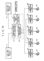
- the communication controller 20 includes a communication data distributor 28 to determine the radio device 10 or 11 as the destination of data.
- the distributor 28 indicates the path selector 21 to send a data packet to the device 10 or 11 determined as the destination of data.
- the path selecting section 21 selects a communication path to the radio device 10 or 11 to deliver a data packet thereto.
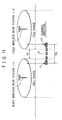
- the mobile communication system of the fifth embodiment can increase the period of time in which the linked state is kept established for the radio devices 10 and 11.
- the distance R1 between the cells of the base stations becomes shorter.
- the period of time in which the linked state is kept established for the radio devices 10 and 11 is elongated.
- the linked state for the devices 10 and 11 is kept retained for a band zone expressed as R2 - R1.
- the mobile unit 2 can use only one radio band.
- the networks established in the mobile unit 2 in the embodiments of the mobile communication system are not limitative. That is, wired and wireless networks can also be used.
- the network in the mobile unit 2 may be configured as a combination of wireless and wired communication paths.
- a first-end radio device mounted in a first-end section of a mobile unit and linked with a fixed radio base station or a last-end radio device mounted in a last-end section of the mobile unit and linked with a fixed radio base station is selected.
- the radio device thus selected is connected to a plurality of mobile terminals in the mobile unit to construct a communication network. Therefore, even when cells formed by the base stations are apart from each other, communication can be continuously carried out by readily conducting a switching operation between the cells. It is consequently possible to reduce the number of fixed radio base stations installed in the system.
- the switching operation between the cells is easily carried out to conduct continuous communication.
- a first-end radio device(10) mounted in a first-end section of a mobile unit and linked with one of fixed radio base stations(1-1 to 1-N) or a last-end radio device(11) mounted in a last-end section of a mobile unit and linked with one of fixed radio base stations(1-1 to 1-N) is selected.
- a communication network is established between the first-end or last-end radio device(10, 11) thus selected and a plurality of mobile terminals in the mobile unit.
Landscapes
- Engineering & Computer Science (AREA)
- Computer Networks & Wireless Communication (AREA)
- Signal Processing (AREA)
- Aviation & Aerospace Engineering (AREA)
- Mobile Radio Communication Systems (AREA)
Applications Claiming Priority (2)
| Application Number | Priority Date | Filing Date | Title |
|---|---|---|---|
| JP2003188921 | 2003-06-30 | ||
| JP2003188921A JP4289043B2 (ja) | 2003-06-30 | 2003-06-30 | 移動体通信システム、移動体、通信制御方法及び通信制御プログラム |
Publications (2)
| Publication Number | Publication Date |
|---|---|
| EP1494496A1 true EP1494496A1 (de) | 2005-01-05 |
| EP1494496B1 EP1494496B1 (de) | 2008-03-26 |
Family
ID=33432297
Family Applications (1)
| Application Number | Title | Priority Date | Filing Date |
|---|---|---|---|
| EP04015420A Expired - Lifetime EP1494496B1 (de) | 2003-06-30 | 2004-06-30 | Mobiles Kommunikationssystem und dazugehöriges Kommunikationssteuerverfahren |
Country Status (6)
| Country | Link |
|---|---|
| US (1) | US7096000B2 (de) |
| EP (1) | EP1494496B1 (de) |
| JP (1) | JP4289043B2 (de) |
| KR (1) | KR100649412B1 (de) |
| CN (1) | CN1328916C (de) |
| DE (1) | DE602004012661T2 (de) |
Families Citing this family (20)
| Publication number | Priority date | Publication date | Assignee | Title |
|---|---|---|---|---|
| CN1816976A (zh) * | 2003-06-30 | 2006-08-09 | 日本电气株式会社 | 通信系统 |
| JP4355599B2 (ja) * | 2004-03-17 | 2009-11-04 | 富士通株式会社 | ブロードバンド路車間通信システム |
| GB2421875B (en) * | 2004-12-31 | 2007-06-06 | Motorola Inc | Mobile communication system and controller, mobile station and method for use therein |
| US7646355B2 (en) * | 2005-05-04 | 2010-01-12 | Sandwave Ip, Llc | Enclosure with ground plane |
| US7664504B2 (en) * | 2005-07-14 | 2010-02-16 | Sandwave Ip, Llc | Virtual cells for wireless networks |
| KR100741414B1 (ko) * | 2005-12-08 | 2007-07-20 | 한국전자통신연구원 | 분산 무선 시스템에서의 이중 가상셀 구조를 형성하는 장치및 그 운용 방법 |
| US8504678B2 (en) * | 2005-12-30 | 2013-08-06 | Sandwave Ip, Llc | Traffic routing based on geophysical location |
| US20070167171A1 (en) * | 2005-12-30 | 2007-07-19 | Mediacell Licensing Corp | Determining the Location of a Device Having Two Communications Connections |
| US8582498B2 (en) * | 2006-03-07 | 2013-11-12 | Sandwave Ip, Llc | Service subscription using geophysical location |
| US8755804B2 (en) * | 2006-08-18 | 2014-06-17 | Wifi Rail, Inc | System for providing redundant communication with mobile devices |
| EP1995985B1 (de) * | 2007-05-22 | 2009-11-18 | Nethawk Oyj | Verfahren, Messsystem, Basisstation, Netzwerkelement und Messgerät |
| US8326156B2 (en) | 2009-07-07 | 2012-12-04 | Fiber-Span, Inc. | Cell phone/internet communication system for RF isolated areas |
| JP2011077635A (ja) * | 2009-09-29 | 2011-04-14 | Panasonic Corp | 無線基地局およびハンドオーバ指示方法 |
| KR101585067B1 (ko) * | 2009-10-28 | 2016-01-13 | 삼성전자주식회사 | 최적화된 망접속 구조를 갖는 통신 시스템 |
| US8918062B2 (en) * | 2009-12-08 | 2014-12-23 | Qualcomm Incorporated | Combined intelligent receive diversity (IRD) and mobile transmit diversity (MTD) with independent antenna switching for uplink and downlink |
| US20110250926A1 (en) * | 2009-12-21 | 2011-10-13 | Qualcomm Incorporated | Dynamic antenna selection in a wireless device |
| JP5312671B2 (ja) * | 2010-02-19 | 2013-10-09 | 三菱電機株式会社 | 列車制御システムおよび列車制御システムにおけるハンドオーバ方法 |
| KR20120071757A (ko) * | 2010-12-23 | 2012-07-03 | 한국전자통신연구원 | 이동 수단을 위한 무선랜 서비스 제공장치 및 시스템 |
| JP5847451B2 (ja) * | 2011-06-21 | 2016-01-20 | 株式会社東芝 | 列車制御システムにおける地上制御装置、地上制御方法及び通信方法 |
| KR101597280B1 (ko) * | 2011-12-12 | 2016-02-24 | 한국전자통신연구원 | 고속철도용 무선통신망의 안정적 이중화 운용방법 및 무선통신 기반 고속철도 제어 시스템 |
Citations (4)
| Publication number | Priority date | Publication date | Assignee | Title |
|---|---|---|---|---|
| EP0726689A2 (de) * | 1995-02-11 | 1996-08-14 | Alcatel SEL Aktiengesellschaft | Mobilfunksystem und Verfahren zur Übergabe einer Funkverbindung |
| EP0933898A1 (de) * | 1997-06-24 | 1999-08-04 | Ntt Mobile Communications Network Inc. | Kommunikationssystem, kommunikationssteuerverfahren und kommunikationssteuerung |
| US5970408A (en) * | 1997-05-02 | 1999-10-19 | Telefonaktiebolaget L/M Ericsson (Publ) | Communication control circuitry and method for a group of commonly-moving mobile transceiver units |
| US6345186B1 (en) * | 1998-12-11 | 2002-02-05 | Telefonaktiebolaget Lm Ericsson (Publ) | Arrangement, system and method relating to mobile communications |
Family Cites Families (4)
| Publication number | Priority date | Publication date | Assignee | Title |
|---|---|---|---|---|
| US5673307A (en) * | 1994-02-17 | 1997-09-30 | Spectralink Corporation | Handoff method for indoor cellular phone system |
| JPH09327057A (ja) | 1996-06-06 | 1997-12-16 | Hitachi Ltd | 移動通信システムおよびその通信制御方法 |
| JPH10164640A (ja) | 1996-11-28 | 1998-06-19 | Matsushita Electric Works Ltd | 移動体通信システム |
| JPH11298967A (ja) | 1998-04-14 | 1999-10-29 | Mitsubishi Heavy Ind Ltd | 乗物用ネットワークおよび乗物用ネットワークにおける通信方法 |
-
2003
- 2003-06-30 JP JP2003188921A patent/JP4289043B2/ja not_active Expired - Lifetime
-
2004
- 2004-06-24 US US10/874,212 patent/US7096000B2/en not_active Expired - Lifetime
- 2004-06-29 CN CNB2004100619605A patent/CN1328916C/zh not_active Expired - Fee Related
- 2004-06-30 EP EP04015420A patent/EP1494496B1/de not_active Expired - Lifetime
- 2004-06-30 DE DE602004012661T patent/DE602004012661T2/de not_active Expired - Lifetime
- 2004-06-30 KR KR1020040050104A patent/KR100649412B1/ko not_active Expired - Fee Related
Patent Citations (4)
| Publication number | Priority date | Publication date | Assignee | Title |
|---|---|---|---|---|
| EP0726689A2 (de) * | 1995-02-11 | 1996-08-14 | Alcatel SEL Aktiengesellschaft | Mobilfunksystem und Verfahren zur Übergabe einer Funkverbindung |
| US5970408A (en) * | 1997-05-02 | 1999-10-19 | Telefonaktiebolaget L/M Ericsson (Publ) | Communication control circuitry and method for a group of commonly-moving mobile transceiver units |
| EP0933898A1 (de) * | 1997-06-24 | 1999-08-04 | Ntt Mobile Communications Network Inc. | Kommunikationssystem, kommunikationssteuerverfahren und kommunikationssteuerung |
| US6345186B1 (en) * | 1998-12-11 | 2002-02-05 | Telefonaktiebolaget Lm Ericsson (Publ) | Arrangement, system and method relating to mobile communications |
Also Published As
| Publication number | Publication date |
|---|---|
| US7096000B2 (en) | 2006-08-22 |
| CN1328916C (zh) | 2007-07-25 |
| KR20050002640A (ko) | 2005-01-07 |
| DE602004012661D1 (de) | 2008-05-08 |
| KR100649412B1 (ko) | 2006-11-24 |
| JP4289043B2 (ja) | 2009-07-01 |
| DE602004012661T2 (de) | 2009-05-20 |
| CN1578194A (zh) | 2005-02-09 |
| HK1072843A1 (en) | 2005-09-09 |
| US20040266444A1 (en) | 2004-12-30 |
| JP2005026919A (ja) | 2005-01-27 |
| EP1494496B1 (de) | 2008-03-26 |
Similar Documents
| Publication | Publication Date | Title |
|---|---|---|
| EP1494496B1 (de) | Mobiles Kommunikationssystem und dazugehöriges Kommunikationssteuerverfahren | |
| EP1471665B1 (de) | Nahtloses umschalten in einem kombinierten drahtlosen kommunikationssystem für grosse und kleine distanzen | |
| US6243575B1 (en) | Mobile communication system, mobile base station, and method of controlling them | |
| US8874115B2 (en) | Method and system for supporting handover between macro base station and vehicular base station | |
| JP2004538732A (ja) | セルラー無線システムにおけるハンドオーバ | |
| EP1215930B1 (de) | Sendeempfangsstation und Verfahren für dessen Benutzung bei zellularer Funkkommunikation | |
| JP4140633B2 (ja) | 通信システム | |
| EP1804437A1 (de) | Mobilfunkgerät und Kanalumschaltungsverfahren zur Kommunikation Ad-hoc | |
| KR20000022799A (ko) | 통신의 강제 절단의 발생율을 감소시키기 위한 핸드 오프 제어 | |
| CN112533265B (zh) | 基于无线测距的多网关无线信道及网络路由快速切换方法 | |
| JPH1146380A (ja) | セルラ方式の移動通信システム | |
| KR20040037637A (ko) | 무선통신 단말기의 통신경로 선택장치 | |
| JPS6329862B2 (de) | ||
| JP2001513286A (ja) | ホームセルを加入者局に割り当てる方法 | |
| JP2946492B2 (ja) | セルラ移動通信方式 | |
| WO1998052366A2 (en) | Method and apparatus for dynamically adjusting number of handover guard channels in a mobile communication system | |
| JPS6090441A (ja) | 移動通信のゾ−ン切替え方式 | |
| HK1072843B (en) | Mobile communication system and communication control method for the same | |
| JP3392825B2 (ja) | データ通信方法及びそのシステム | |
| JPH0514265A (ja) | 移動通信装置 | |
| JP2001507540A (ja) | 無線ネットワークのホットスポットエリアの位置を決定するための方法及びトランシーバ | |
| JPH0888877A (ja) | 移動通信における移動機の基地局選択方式 | |
| JP2009004829A (ja) | 基地局、サーバ装置及び無線lanシステム | |
| JPH07123460A (ja) | 移動体通信システムの迂回呼接続制御方式 | |
| EP1364485B1 (de) | Apparat und zugeordnetes verfahren zum erbringen eines wlan dienstes in einem stationären, drahtlosen zugangskommunikationssystem |
Legal Events
| Date | Code | Title | Description |
|---|---|---|---|
| PUAI | Public reference made under article 153(3) epc to a published international application that has entered the european phase |
Free format text: ORIGINAL CODE: 0009012 |
|
| AK | Designated contracting states |
Kind code of ref document: A1 Designated state(s): AT BE BG CH CY CZ DE DK EE ES FI FR GB GR HU IE IT LI LU MC NL PL PT RO SE SI SK TR |
|
| AX | Request for extension of the european patent |
Extension state: AL HR LT LV MK |
|
| 17P | Request for examination filed |
Effective date: 20050616 |
|
| AKX | Designation fees paid |
Designated state(s): DE FR GB |
|
| GRAP | Despatch of communication of intention to grant a patent |
Free format text: ORIGINAL CODE: EPIDOSNIGR1 |
|
| GRAS | Grant fee paid |
Free format text: ORIGINAL CODE: EPIDOSNIGR3 |
|
| GRAA | (expected) grant |
Free format text: ORIGINAL CODE: 0009210 |
|
| AK | Designated contracting states |
Kind code of ref document: B1 Designated state(s): DE FR GB |
|
| REG | Reference to a national code |
Ref country code: GB Ref legal event code: FG4D |
|
| REF | Corresponds to: |
Ref document number: 602004012661 Country of ref document: DE Date of ref document: 20080508 Kind code of ref document: P |
|
| ET | Fr: translation filed | ||
| PLBE | No opposition filed within time limit |
Free format text: ORIGINAL CODE: 0009261 |
|
| STAA | Information on the status of an ep patent application or granted ep patent |
Free format text: STATUS: NO OPPOSITION FILED WITHIN TIME LIMIT |
|
| 26N | No opposition filed |
Effective date: 20081230 |
|
| REG | Reference to a national code |
Ref country code: FR Ref legal event code: PLFP Year of fee payment: 13 |
|
| REG | Reference to a national code |
Ref country code: FR Ref legal event code: PLFP Year of fee payment: 14 |
|
| PGFP | Annual fee paid to national office [announced via postgrant information from national office to epo] |
Ref country code: FR Payment date: 20170511 Year of fee payment: 14 Ref country code: GB Payment date: 20170628 Year of fee payment: 14 |
|
| PGFP | Annual fee paid to national office [announced via postgrant information from national office to epo] |
Ref country code: DE Payment date: 20170627 Year of fee payment: 14 |
|
| REG | Reference to a national code |
Ref country code: DE Ref legal event code: R119 Ref document number: 602004012661 Country of ref document: DE |
|
| GBPC | Gb: european patent ceased through non-payment of renewal fee |
Effective date: 20180630 |
|
| PG25 | Lapsed in a contracting state [announced via postgrant information from national office to epo] |
Ref country code: DE Free format text: LAPSE BECAUSE OF NON-PAYMENT OF DUE FEES Effective date: 20190101 Ref country code: GB Free format text: LAPSE BECAUSE OF NON-PAYMENT OF DUE FEES Effective date: 20180630 Ref country code: FR Free format text: LAPSE BECAUSE OF NON-PAYMENT OF DUE FEES Effective date: 20180630 |