EP1494510A1 - Zündgerät mit intelligenter Abschaltung - Google Patents
Zündgerät mit intelligenter Abschaltung Download PDFInfo
- Publication number
- EP1494510A1 EP1494510A1 EP04012533A EP04012533A EP1494510A1 EP 1494510 A1 EP1494510 A1 EP 1494510A1 EP 04012533 A EP04012533 A EP 04012533A EP 04012533 A EP04012533 A EP 04012533A EP 1494510 A1 EP1494510 A1 EP 1494510A1
- Authority
- EP
- European Patent Office
- Prior art keywords
- ignition
- gas discharge
- time
- discharge lamp
- lamp
- Prior art date
- Legal status (The legal status is an assumption and is not a legal conclusion. Google has not performed a legal analysis and makes no representation as to the accuracy of the status listed.)
- Granted
Links
Images



Classifications
-
- H—ELECTRICITY
- H05—ELECTRIC TECHNIQUES NOT OTHERWISE PROVIDED FOR
- H05B—ELECTRIC HEATING; ELECTRIC LIGHT SOURCES NOT OTHERWISE PROVIDED FOR; CIRCUIT ARRANGEMENTS FOR ELECTRIC LIGHT SOURCES, IN GENERAL
- H05B41/00—Circuit arrangements or apparatus for igniting or operating discharge lamps
- H05B41/02—Details
- H05B41/04—Starting switches
- H05B41/042—Starting switches using semiconductor devices
-
- H—ELECTRICITY
- H05—ELECTRIC TECHNIQUES NOT OTHERWISE PROVIDED FOR
- H05B—ELECTRIC HEATING; ELECTRIC LIGHT SOURCES NOT OTHERWISE PROVIDED FOR; CIRCUIT ARRANGEMENTS FOR ELECTRIC LIGHT SOURCES, IN GENERAL
- H05B41/00—Circuit arrangements or apparatus for igniting or operating discharge lamps
- H05B41/14—Circuit arrangements
- H05B41/26—Circuit arrangements in which the lamp is fed by power derived from DC by means of a converter, e.g. by high-voltage DC
- H05B41/28—Circuit arrangements in which the lamp is fed by power derived from DC by means of a converter, e.g. by high-voltage DC using static converters
- H05B41/288—Circuit arrangements in which the lamp is fed by power derived from DC by means of a converter, e.g. by high-voltage DC using static converters with semiconductor devices and specially adapted for lamps without preheating electrodes, e.g. for high-intensity discharge lamps, high-pressure mercury or sodium lamps or low-pressure sodium lamps
- H05B41/292—Arrangements for protecting lamps or circuits against abnormal operating conditions
- H05B41/2921—Arrangements for protecting lamps or circuits against abnormal operating conditions for protecting the circuit against abnormal operating conditions
- H05B41/2925—Arrangements for protecting lamps or circuits against abnormal operating conditions for protecting the circuit against abnormal operating conditions against abnormal lamp operating conditions
Definitions
- the invention relates to an ignitor for gas discharge lamps, in particular with electromagnetic ballast and a method for igniting and re-igniting gas discharge lamps.
- Gas discharge lamps such as sodium vapor lamps, Metallic vapor halide lamps, especially when used as high-pressure gas discharge lamps are trained, are usually sensitive to mains voltage fluctuations.
- the mains voltage superimposed interference voltages can high pressure gas discharge lamps to extinguish.
- the reignition needs in the Rule of a lamp type dependent time which is in the range of a few seconds to several minutes. This applies in particular if the igniter emits ignition voltage, the Although not to ignite a cold but to ignite a hot Lamp is sufficient.
- EP 0 847 680 B1 discloses a method for the operation or ignition of high-pressure gas discharge lamps, in which after an unintentional shutdown of the Lamp the number of lamp firings is counted and the Ignition circuit is switched off when the lamp after a predetermined number of lamp ignitions again unintentionally off.
- the solution to the problem lies in the definition of a critical Burning time and monitoring whether the high-pressure gas discharge lamp burns longer than this time. Fills the high-pressure gas discharge lamp this condition, it will be considered operational classified and operated. Turn it off, however within the critical burning time, this is registered. Following several such registrations, these registrations are counted. Exceeds the count a predetermined or alternatively also specifiable value is the lamp classified as worn and shut down. This For example, value is set to three events. He can however, if necessary, be set larger or smaller.
- the critical burning time is set so that on the one hand so great is that a occurring at the end of life Periodic extinction takes place at intervals, the shorter are the critical burning time, whereas the other Probability of several consecutive network disturbances, which can lead to lamp extinction within the critical burning time is very low.
- the critical firing time can be set to one or more hours.
- the ignitor contains a discriminator for differentiation from cold and warm start.
- This also as cold-start detection device designated discriminator sets the resettable Erase counter upon detection of a cold start preferably to its initial value, so even gone in advance Firing cycle as defect switched off high-pressure gas discharge lamps be ignited first. Is the counter at the value 3? set, they remain after the third unintentional extinguishing permanently switched off until the next cold start.
- a discriminator for differentiation from cold and warm start.
- This also as cold-start detection device designated discriminator sets the resettable Erase counter upon detection of a cold start preferably to its initial value, so even gone in advance Firing cycle as defect switched off high-pressure gas discharge lamps be ignited first. Is the counter at the value 3? set, they remain after the third unintentional extinguishing permanently switched off until the next cold start.
- FIG. 1 shows the circuit diagram of a gas discharge lamp 1 and an associated ballast 2 and an ignitor 3 illustrates.
- the gas discharge lamp 1 is, for example a sodium vapor lamp, a metal halide lamp or another gas discharge lamp. While you have a connection is connected to a reference potential N is her another connection via a Zündimpulstransformator 4 and the Ballast 2 to an AC voltage leading line L. connected. The reference potential N and the line L can be interchanged with each other.
- the ballast 2 is in simplest case of a choke which serves to limit the lamp current of the gas discharge lamp 1 and the Stabilize gas discharge.
- the ignition pulse transformer 4 has a secondary winding between the ballast 2 and the gas discharge lamp 1 is connected. His primary winding is connected to the ignitor 3.
- the other end of the primary winding the Zündimpulstransformators 4 is over a Break-through switch device, such as the Sidac 7, connected, the other end with the intermediate potential 6 is connected. The latter is via a current limiting resistor 8 and a capacitor 9 with the reference potential N. connected.
- the Zündimpulstransformator 4 forms together with the ignitor 3 is a high voltage generator 11.
- the control circuit 12 can also be parallel to the capacitor 5 are switched.
- the control circuit 12 is out of sight 7 sidacs a switch 15 shorting the sidac 7 can to prevent the generation of ignition pulses.
- the control circuit 12 includes an electronic circuit 16 for driving the switch 15.
- the control circuit monitors the voltage applied to the terminals 13, 14 voltage and evaluate these. It is through in the preferred case a microcontroller 17 is formed, which corresponds to that of FIG. 4 is provided schematically apparent external circuit.
- a microcontroller 17 is formed, which corresponds to that of FIG. 4 is provided schematically apparent external circuit.
- the Switch 15 is connected through a thyristor with upstream Graetz Bridge 18 formed.
- the thyristor is a working resistor 19 connected in series.
- the microcontroller 17 controls the thyristor at its gate.
- a resistor 21 branches in conjunction with a Zener diode 22 the operating voltage for the microcontroller 17 from.
- the zener diode 22, a buffer capacitor 23 may be connected in parallel.
- the Zener diode 22 can also be replaced by a voltage regulator become.
- the microcontroller 17 is a recognition device 24th assigned to short-term operating voltage dips that too cause an unintentional extinguishing of the gas discharge lamp or can lead to recognize.
- This recognition device 24 supplies at operating voltage interruptions from the buffer capacitor 23 are bridged, a short signal pulse to a corresponding input of the microcontroller 17, to signal that now a re-ignition pending.
- the recognizer 24 is included in the embodiment According to Figure 4, 4a or Figure 4b one with the Graetz bridge 18 and thus the unfiltered operating voltage connected Zener diode 25 whose other electrode (anode) with the associated input of the microcontroller 17 is connected (dashed components are optional). With this are as well a resistor 27 and optionally a capacitor 26 connected the two switched to ground and thus turn connected to the other end of the Graetz bridge 18.
- the Zener diode 25 can also be replaced by a resistor.
- the microcontroller 17 is program-controlled. His programming takes place in the appropriate for the specific type Language for performing the function described below.
- the Zündimpulstransformator therefore generates a Sequence of ignition pulses. With a cold lamp these lead in the Usually immediately to ignite the gas discharge lamp 1. This ignites thus at the first half-wave or shortly thereafter. burns the gas discharge lamp 1 decreases the voltage between the ballast 2 and the gas discharge lamp 1 so far that the Capacitor 5 the breakdown voltage of the Sidacs 7 no longer reached. There are thus no more ignition pulses generated.
- the microcontroller 17 remains active. Although at the terminals 13, 14 the supply of the control circuit 12 for a short time This can be omitted by the buffer capacitor 23 bridged.
- the Zener diode 25 indicates the operational breakdown or However, other interference pulse directly to the input of Microcontroller 17 continues, making this particular reference the sudden increase in voltage between the terminals 13, 14 recognizes that the gas discharge lamp 1 in the meantime is extinguished. He now leads the start of the gas discharge lamp 1 in "Warm ignition” or "Re-ignition mode" by.
- the re-ignition mode monitors how long the unsuccessful Emission of ignition pulses to the gas discharge lamp 1 takes.
- the breaks between individual ignition attempts can be extended for example, 52 seconds or 1 minute.
- the duration of the ignition attempts can be extended be, for example, 24 seconds.
- the from the embodiment described above by the Programming the microcontroller 17 is different, is during warm - up (re - ignition) the time from extinguishing the Lamp until successful re-ignition or alternatively the Number of ignition tests carried out and monitored during considered next reignition.
- the number of Re-ignition tests occurring in a given period monitored in the event of unintentional extinction of the gas discharge lamp 1 and any new Wiederzünd bath be prevented if a given limit is exceeded. hereby it avoids that at the end of life arrived lamps, which are constantly re-extinguished, constantly re-ignited which causes unpleasant blinking effects would.
- FIG 2 illustrates a modified embodiment the circuit of Figure 1, wherein for the same circuit parts with reference to the previous description, the same reference numerals be based on.
- the embodiment of FIG 2 differs from that of Figure 1 by the arrangement the control circuit 12 'in a lamp current carrying path.
- the functional description also applies corresponding.
- FIG 3 illustrates an embodiment of the circuit for the gas discharge lamp 1, which without Zündimpulstransformator gets along.
- the ballast 2 with a Tapped. This tap is via a capacitor 28, a triac 29 and an optional current limiting resistor 31 or alternatively a throttle to the reference potential N connected.
- the control electrode of the triac 19 is connected via a Diac 32 to one of two resistors 33, 34 existing Voltage divider, which picks up the lamp voltage, connected.
- the resistor 34 is a phase shifter capacitor 35 connected in parallel.
- the switch 15 serves to prevent drive pulses Diacs 29 to the generation of high voltage pulses prevent. If it is open, high voltage pulses are generated until the gas discharge lamp 1 ignites. If he is closed, omits the generation of the ignition pulses.
- the circuit 16 opens and closes the switch 15 according to the diagrams 5 and 6 and the associated description.
- FIG 3a illustrates a modified embodiment the circuit for the gas discharge lamp 1, the without Zündimpulstransformator requires.
- the ballast 2 with a tap provided by a capacitor 28, a triac 29 and an optional current limiting resistor 31 or alternatively a throttle to the reference potential N is connected.
- the control circuit described above 16 is not used here to control a switch 15, the Ignition pulses of the triac 29 shorts, but it controls the triac 29 directly on. Should the generation of Lampenzündimpulsen stay the triac 29 receives no ignition pulses more of the control circuit 16. It is connected to the phase shifter network consisting of the resistors 33, 34 and the capacitor 35 connected to, if necessary, the ignition pulses for to generate the triac 29.
- the detection of warm start situations takes place as in the circuit of Figure 4 wherein the corresponding circuit parts not specified here individually are.
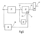
- Figure 5 illustrates the function of the microcontroller 17 as a block diagram.
- Its input 36 leads to a time filter 37, which examines incoming impulses to see if they arrive at a time interval greater than one Minimum time.
- the time filter 37 serves to successive Extinguishing the high-pressure gas discharge lamp as it may flash several times while igniting same accidental extinction during the quiet burning the high-pressure gas discharge lamp 1 in a row of network disturbances can occur.
- the time filter 37 may be, for example set to 1, 3 or 5 seconds. The However, the minimum time specified by him is much lower as the end of life of the high pressure gas discharge lamp. 1 occurring flashing times.
- a Cold starter detection device 38 connected to it serves to distinguish a cold start from a warm start. For example, it compares the temporal relationship of the Arrivals of the operating voltage of the microcontroller 17 with the arrival of a signal at the input 36. Meets this Signal rather than delayed by the buffer capacitor 23 Operating voltage is the cold-start detection device 38 at its output 39 from a reset signal. This becomes too one of two alternative reset inputs 41, 42 of a Counting block 43 passed.
- the count block 43 has a count input 44, which is connected to the output of the time filter 37.
- Its own exit 45 leads to an entrance of an Oder gate 46, whose output 47, the output of the microcontroller 17th forms and controls the gate of the thyristor 15.
- the other entrance the OR gate 46 leads blocking pulses, which consist of more unillustrated blocks of the microcontroller 17 e.g. can come to interrupt the ignition.
- the pulses conducted to the counting input 44 pass also to a timer circuit 48, which is a critical burning time sets.
- the critical burning time can, for example, on one or two hours.
- the output of the timer circuit 48 is connected to the reset input 42. receives the counter block 43 at its reset input 41 or at its Reset input 42 a signal it is at its original value reset. At its output 45, it gives a signal, when at its entrance 44 a predetermined number of Counts received without having reset in the meantime to have been.
- the burning (B) or non-burning (N) is the Gas discharge lamp 1 illustrated as a timing diagram.
- the gas discharge lamp 1 is turned on cold.
- the count block 43 is thereby in consequence of an output signal the cold starter detection means 38 to its basic value of for example 3 reset.
- Lost at a time t2 the gas discharge lamp 2 in turn as a result of a power failure again before the critical burning time Z expired is, the count block 43 is again decremented. He has now the value 1.
- the critical burning time Z expires and that of the last count triggered timer circuit 48 then provides at its output at a time t3 a reset signal for it now has the value 3.
- the gas discharge lamp 1 continues to burn undisturbed.
- you can Place the full reset of the count block 43 also counting in the opposite direction (increment) done. It is also possible, in such a case by several steps x to count up (n: n + x)).
- the step number x can be a given Constant or a variable that stems from the prehistory certainly.
- An ignition method and an ignition device are proposed, where the distances between deletion events of a High-pressure gas discharge lamp 1 are monitored. The supervision the burning or erasing is done by monitoring the Burning voltage. There will only be a certain number of short-term consecutive deletion events allowed. Will the Maximum number of deletion events consecutive in the short term is reached or exceeded the ignitor or the Gas discharge lamp stopped. Will not this maximum number an event counter is reset to its initial value or it will take one or more steps in the opposite direction counted (n + 1 or n + x).
Landscapes
- Circuit Arrangements For Discharge Lamps (AREA)
- Ignition Installations For Internal Combustion Engines (AREA)
- Pharmaceuticals Containing Other Organic And Inorganic Compounds (AREA)
Abstract
Description
- Figur 1 bis 3
- Gasentladungslampen mit Vorschalt- und Zündgerat in unterschiedlichen Ausführungsformen in schematisierten Schaltbildern,
- Figur 3a
- eine Steuerschaltung für die Vorschaltgeräte nach Figur 1 bis 3 in vereinfachter Darstellung,
- Figur 4
- eine andere Steuerschaltung für die Vorschaltgeräte nach Figur 1 bis 3 in vereinfachter Darstellung,
- Figur 4a, 4b
- Schaltungsvarianten für eine Erkennungseinrichtung,
- Figur 5
- einen Teil der Steuerschaltung nach Figur 4 als Blockschaltbild und
- Figur 6
- ein Zeitdiagramm zur Veranschaulichung der Betriebsweise des Zündgeräts.
Claims (12)
- Zündgerät, für Gasentladungslampen (1), insbesondere mit elektromagnetischem Vorschaltgerät (2),
mit einem steuerbaren Hochspannungsgenerator (11), der an die Gasentladungslampe (1) angeschlossen ist, um Zündimpulse an diese zu liefern,
mit einer Steuerschaltung (12), die an den Hochspannungsgenerator (11) angeschlossen ist, um diesen zu steuern, und die in wenigstens zwei unterschiedlichen Betriebsarten betreibbar ist,
mit einer Kaltstarterkennungseinrichtung (38), die mit der Steuerschaltung (12) verbunden ist oder die Teil derselben ist,
mit einem rücksetzbaren Löschzähler (24), der Teil der Steuerschaltung (12) ist oder der an diese angeschlossen ist, um Löschungen und/oder Zündungen der Gasentladungslampe (1) zu zählen und um weitere Zündversuche bis zum nächsten Kaltstart zu unterbinden, wenn ein Zählgrenzwert erreicht ist,
mit einem Timer (38), der durch eine Zündung der Gasentladungslampe (1) getriggert wird und der mit dem Löschzähler (43) verbunden ist, um diesen bei Ablauf seiner Triggerzeit zurückzusetzen. - Zündgerät nach Anspruch 1, dadurch gekennzeichnet, dass dem Löschzähler (43) eine Filterschaltung (37) vorgeschaltet ist, um kurzfristig aufeinander folgende Löschereignisse oder Lampenzündungen nur einfach zu zählen.
- Zündgerät nach Anspruch 2, dadurch gekennzeichnet, dass die Filterschaltung (37) Löschereignisse oder Lampenzündungen ausblendet, die in einem zeitlichen Abstand zueinander auftreten, wie er bei einem Zündvorgang einer intakten Gasentladungslampe (1) zu erwarten ist.
- Zündverfahren für Gasentladungslampen (1) mittels eines Zündgeräts (3), bei dem das Zündgerät (3) bei in Betrieb befindlicher Gasentladungslampe (1) die in einem gegebenen Zeitfenster auftretende Anzahl von Wiederzündvorgängen überwacht und sich für weitere Zündversuche sperrt, wenn eine Maximalzahl von Wiederzündvorgängen überschritten wird.
- Zündverfahren für Gasentladungslampen (1) mittels eines Zündgeräts (3), bei demdas Zündgerät (3) bei in Betrieb befindlicher Gasentladungslampe (1) mit einem Zähler (43) die Anzahl von Wiederzündvorgängen zählt, wobei immer dann um Eins weitergezählt wird, wenn seit dem letzen Wiederzündvorgang eine Zeit verstrichen ist, die kürzer ist als eine Minimalzeit,der Zähler (43) ein- oder mehrstufig in Gegenrichtung zählt oder zurückgesetzt wird, wenn seit dem letzten Wiederzündvorgang eine Brennzeit erreicht wird, die größer ist als eine kritische Brennzeit, unddas Zündgerät für weitere Zündversuche gesperrt wird, wenn der Zähler einen vorgegebenen oder vorgebbaren Zählwert erreicht.
- Zündverfahren nach Anspruch 5, dadurch gekennzeichnet, dass die Minimalzeit gleich der kritischen Brennzeit ist.
- Zündverfahren nach Anspruch 5, dadurch gekennzeichnet, dass ein Wiederzündvorgang nur gezählt wird, wenn der Zeitabstand zu dem letzten Wiederzündvorgang größer ist als eine Mindestzeit.
- Zündverfahren nach Anspruch 7, dadurch gekennzeichnet, dass die Mindestzeit wesentlich geringer ist sowohl als die Minimalzeit als auch als die kritische Brennzeit.
- Zündverfahren nach Anspruch 5, dadurch gekennzeichnet, dass die von dem Zündgerät (11) gelieferten Hochspannungsimpulse zeitlich getaktet geliefert werden.
- Zündverfahren nach Anspruch 14, dadurch gekennzeichnet, dass die Steuerschaltung (12) bei einem Wiederzündvorgang die Wiederzündzeit registriert, die vom Wiederzündbeginn bis zum tatsächlichen Zünden verstreicht, und beim nächsten Wiederzündvorgang eine Wartezeit berücksichtigt.
- Zündverfahren nach Anspruch 10, dadurch gekennzeichnet, dass die Wartezeit anhand der Wiederzündzeit bestimmt wird.
- Zündverfahren nach Anspruch 14, dadurch gekennzeichnet, dass die Steuerschaltung (12) bei einem Wiederzündvorgang die Anzahl der Zündversuche registriert, die vom Wiederzündbeginn bis zum tatsächlichen Zünden unternommen werden, und beim nächsten Wiederzündvorgang eine Wartezeit berücksichtigt, die anhand der Anzahl der vorigen Zündversuche bestimmt wird.
Applications Claiming Priority (2)
| Application Number | Priority Date | Filing Date | Title |
|---|---|---|---|
| DE10330013A DE10330013A1 (de) | 2003-07-03 | 2003-07-03 | Zündgerät mit intelligenter Abschaltung |
| DE10330013 | 2003-07-03 |
Publications (2)
| Publication Number | Publication Date |
|---|---|
| EP1494510A1 true EP1494510A1 (de) | 2005-01-05 |
| EP1494510B1 EP1494510B1 (de) | 2007-05-23 |
Family
ID=33426844
Family Applications (1)
| Application Number | Title | Priority Date | Filing Date |
|---|---|---|---|
| EP04012533A Expired - Lifetime EP1494510B1 (de) | 2003-07-03 | 2004-05-27 | Zündgerät mit intelligenter Abschaltung |
Country Status (5)
| Country | Link |
|---|---|
| EP (1) | EP1494510B1 (de) |
| AT (1) | ATE363194T1 (de) |
| DE (2) | DE10330013A1 (de) |
| DK (1) | DK1494510T3 (de) |
| ES (1) | ES2283900T3 (de) |
Cited By (1)
| Publication number | Priority date | Publication date | Assignee | Title |
|---|---|---|---|---|
| EP1494508A3 (de) * | 2003-07-03 | 2009-05-20 | Elektrobau Oschatz GmbH & Co. KG | Universelles Zündgerät |
Citations (2)
| Publication number | Priority date | Publication date | Assignee | Title |
|---|---|---|---|---|
| EP0252438A1 (de) * | 1986-07-09 | 1988-01-13 | NORKA Norddeutsche Kunststoff- und Elektro-Gesellschaft Stäcker & Co. mbH | Zündgerät für Hochdruckentladungslampen |
| US5969483A (en) * | 1998-03-30 | 1999-10-19 | Motorola | Inverter control method for electronic ballasts |
-
2003
- 2003-07-03 DE DE10330013A patent/DE10330013A1/de not_active Withdrawn
-
2004
- 2004-05-27 EP EP04012533A patent/EP1494510B1/de not_active Expired - Lifetime
- 2004-05-27 AT AT04012533T patent/ATE363194T1/de active
- 2004-05-27 DK DK04012533T patent/DK1494510T3/da active
- 2004-05-27 DE DE502004003861T patent/DE502004003861D1/de not_active Expired - Lifetime
- 2004-05-27 ES ES04012533T patent/ES2283900T3/es not_active Expired - Lifetime
Patent Citations (2)
| Publication number | Priority date | Publication date | Assignee | Title |
|---|---|---|---|---|
| EP0252438A1 (de) * | 1986-07-09 | 1988-01-13 | NORKA Norddeutsche Kunststoff- und Elektro-Gesellschaft Stäcker & Co. mbH | Zündgerät für Hochdruckentladungslampen |
| US5969483A (en) * | 1998-03-30 | 1999-10-19 | Motorola | Inverter control method for electronic ballasts |
Cited By (1)
| Publication number | Priority date | Publication date | Assignee | Title |
|---|---|---|---|---|
| EP1494508A3 (de) * | 2003-07-03 | 2009-05-20 | Elektrobau Oschatz GmbH & Co. KG | Universelles Zündgerät |
Also Published As
| Publication number | Publication date |
|---|---|
| EP1494510B1 (de) | 2007-05-23 |
| DE502004003861D1 (de) | 2007-07-05 |
| DE10330013A1 (de) | 2005-02-03 |
| ATE363194T1 (de) | 2007-06-15 |
| DK1494510T3 (da) | 2007-10-01 |
| ES2283900T3 (es) | 2007-11-01 |
Similar Documents
| Publication | Publication Date | Title |
|---|---|---|
| DE19531622B4 (de) | Zündschaltung für eine Hochdruck-Gasentladungslampe | |
| DE3046617C2 (de) | ||
| DE4136486A1 (de) | Vorschaltgeraet zum starten und betreiben von wechselstrom-hochdruck-gasentladungslampen | |
| EP0847680B1 (de) | Verfahren und schaltungsanordnung zum zünden einer hochdruck-gasentladungslampe | |
| DE3887262T2 (de) | Wechselrichter zum Zünden und Speisen einer Gasentladungslampe. | |
| DE60109446T2 (de) | Zündschaltung | |
| EP0614052A2 (de) | Feuerungsautomat | |
| EP1494510B1 (de) | Zündgerät mit intelligenter Abschaltung | |
| EP1086609B1 (de) | Zünder für eine gasentladungslampe, insbesondere hochdruck-gasentladungslampe für kraftfahrzeugscheinwerfer | |
| EP1494508B1 (de) | Universelles Zündgerät | |
| DE3625499C2 (de) | ||
| DE3127876A1 (de) | Verfahren und einrichtung zum starten von leuchtstofflampen | |
| EP1618766B1 (de) | Zündschaltung mit geregelter zündspannung | |
| DE2606088A1 (de) | Brenner-regelvorrichtung | |
| DE3227170C2 (de) | Verfahren zur Signalisierung über eine Beleuchtungsanlage | |
| EP0252438A1 (de) | Zündgerät für Hochdruckentladungslampen | |
| DE3126639C2 (de) | ||
| DE19805801A1 (de) | Lampen-Steuerschaltung | |
| DE19955001C1 (de) | Zündeinheit für Gas-Durchlauferhitzer | |
| DE3411300C2 (de) | Elektronische Schaltungsanordnung für Feuerungsautomaten | |
| DE2904875A1 (de) | Schaltanordnung fuer ein sicherheitslicht-versorgungsgeraet fuer leuchtstofflampen | |
| DE1764238C2 (de) | Schaltanordnung zum gleichzeitigen oder zeitlich aufeinanderfolgenden Zünden und Löschen von Hochspannungsleuchtröhrenanlagen aus mehreren im gleichen Versorgungskreis liegenden, eine oder mehrere Leuchtröhren enthaltenden Leuchtröhrensystemen | |
| DE29522356U1 (de) | Zündschaltung für eine Hochdruck-Gasentladungslampe | |
| DE1100168B (de) | Schaltungsanordnung zum gleichzeitigen Zuenden einer groesseren Anzahl von Niederspannungs-Leuchtstofflampen | |
| DE4333884A1 (de) | Zündschaltung für eine Hochdruck-Gasentladungslampe |
Legal Events
| Date | Code | Title | Description |
|---|---|---|---|
| PUAI | Public reference made under article 153(3) epc to a published international application that has entered the european phase |
Free format text: ORIGINAL CODE: 0009012 |
|
| AK | Designated contracting states |
Kind code of ref document: A1 Designated state(s): AT BE BG CH CY CZ DE DK EE ES FI FR GB GR HU IE IT LI LU MC NL PL PT RO SE SI SK TR |
|
| AX | Request for extension of the european patent |
Extension state: AL HR LT LV MK |
|
| 17P | Request for examination filed |
Effective date: 20050211 |
|
| AKX | Designation fees paid |
Designated state(s): AT BE BG CH CY CZ DE DK EE ES FI FR GB GR HU IE IT LI LU MC NL PL PT RO SE SI SK TR |
|
| GRAP | Despatch of communication of intention to grant a patent |
Free format text: ORIGINAL CODE: EPIDOSNIGR1 |
|
| GRAS | Grant fee paid |
Free format text: ORIGINAL CODE: EPIDOSNIGR3 |
|
| GRAA | (expected) grant |
Free format text: ORIGINAL CODE: 0009210 |
|
| STAA | Information on the status of an ep patent application or granted ep patent |
Free format text: STATUS: THE PATENT HAS BEEN GRANTED |
|
| AK | Designated contracting states |
Kind code of ref document: B1 Designated state(s): AT BE BG CH CY CZ DE DK EE ES FI FR GB GR HU IE IT LI LU MC NL PL PT RO SE SI SK TR |
|
| REG | Reference to a national code |
Ref country code: GB Ref legal event code: FG4D Free format text: NOT ENGLISH |
|
| GBT | Gb: translation of ep patent filed (gb section 77(6)(a)/1977) |
Effective date: 20070523 |
|
| REG | Reference to a national code |
Ref country code: CH Ref legal event code: EP Ref country code: CH Ref legal event code: NV Representative=s name: KIRKER & CIE S.A. |
|
| REG | Reference to a national code |
Ref country code: IE Ref legal event code: FG4D Free format text: LANGUAGE OF EP DOCUMENT: GERMAN |
|
| REF | Corresponds to: |
Ref document number: 502004003861 Country of ref document: DE Date of ref document: 20070705 Kind code of ref document: P |
|
| REG | Reference to a national code |
Ref country code: SE Ref legal event code: TRGR |
|
| REG | Reference to a national code |
Ref country code: DK Ref legal event code: T3 |
|
| REG | Reference to a national code |
Ref country code: ES Ref legal event code: FG2A Ref document number: 2283900 Country of ref document: ES Kind code of ref document: T3 |
|
| PG25 | Lapsed in a contracting state [announced via postgrant information from national office to epo] |
Ref country code: PL Free format text: LAPSE BECAUSE OF FAILURE TO SUBMIT A TRANSLATION OF THE DESCRIPTION OR TO PAY THE FEE WITHIN THE PRESCRIBED TIME-LIMIT Effective date: 20070523 |
|
| PG25 | Lapsed in a contracting state [announced via postgrant information from national office to epo] |
Ref country code: CZ Free format text: LAPSE BECAUSE OF FAILURE TO SUBMIT A TRANSLATION OF THE DESCRIPTION OR TO PAY THE FEE WITHIN THE PRESCRIBED TIME-LIMIT Effective date: 20070523 Ref country code: MC Free format text: LAPSE BECAUSE OF NON-PAYMENT OF DUE FEES Effective date: 20070531 Ref country code: BG Free format text: LAPSE BECAUSE OF FAILURE TO SUBMIT A TRANSLATION OF THE DESCRIPTION OR TO PAY THE FEE WITHIN THE PRESCRIBED TIME-LIMIT Effective date: 20070823 Ref country code: PT Free format text: LAPSE BECAUSE OF FAILURE TO SUBMIT A TRANSLATION OF THE DESCRIPTION OR TO PAY THE FEE WITHIN THE PRESCRIBED TIME-LIMIT Effective date: 20071023 Ref country code: SI Free format text: LAPSE BECAUSE OF FAILURE TO SUBMIT A TRANSLATION OF THE DESCRIPTION OR TO PAY THE FEE WITHIN THE PRESCRIBED TIME-LIMIT Effective date: 20070523 |
|
| PG25 | Lapsed in a contracting state [announced via postgrant information from national office to epo] |
Ref country code: SK Free format text: LAPSE BECAUSE OF FAILURE TO SUBMIT A TRANSLATION OF THE DESCRIPTION OR TO PAY THE FEE WITHIN THE PRESCRIBED TIME-LIMIT Effective date: 20070523 |
|
| PLAZ | Examination of admissibility of opposition: despatch of communication + time limit |
Free format text: ORIGINAL CODE: EPIDOSNOPE2 |
|
| PLBI | Opposition filed |
Free format text: ORIGINAL CODE: 0009260 |
|
| 26 | Opposition filed |
Opponent name: TRIDONICATCO GMBH & CO.KG Effective date: 20080226 |
|
| PG25 | Lapsed in a contracting state [announced via postgrant information from national office to epo] |
Ref country code: GR Free format text: LAPSE BECAUSE OF FAILURE TO SUBMIT A TRANSLATION OF THE DESCRIPTION OR TO PAY THE FEE WITHIN THE PRESCRIBED TIME-LIMIT Effective date: 20070824 |
|
| PLAQ | Examination of admissibility of opposition: information related to despatch of communication + time limit deleted |
Free format text: ORIGINAL CODE: EPIDOSDOPE2 |
|
| PG25 | Lapsed in a contracting state [announced via postgrant information from national office to epo] |
Ref country code: RO Free format text: LAPSE BECAUSE OF FAILURE TO SUBMIT A TRANSLATION OF THE DESCRIPTION OR TO PAY THE FEE WITHIN THE PRESCRIBED TIME-LIMIT Effective date: 20070523 |
|
| NLR1 | Nl: opposition has been filed with the epo |
Opponent name: TRIDONICATCO GMBH & CO.KG |
|
| PG25 | Lapsed in a contracting state [announced via postgrant information from national office to epo] |
Ref country code: EE Free format text: LAPSE BECAUSE OF FAILURE TO SUBMIT A TRANSLATION OF THE DESCRIPTION OR TO PAY THE FEE WITHIN THE PRESCRIBED TIME-LIMIT Effective date: 20070523 |
|
| PLBG | Opposition deemed not to have been filed |
Free format text: ORIGINAL CODE: 0009274 |
|
| 26D | Opposition deemed not to have been filed |
Opponent name: TRIDONICATCO GMBH & CO.KG Effective date: 20090415 |
|
| PG25 | Lapsed in a contracting state [announced via postgrant information from national office to epo] |
Ref country code: CY Free format text: LAPSE BECAUSE OF FAILURE TO SUBMIT A TRANSLATION OF THE DESCRIPTION OR TO PAY THE FEE WITHIN THE PRESCRIBED TIME-LIMIT Effective date: 20070523 |
|
| PG25 | Lapsed in a contracting state [announced via postgrant information from national office to epo] |
Ref country code: LU Free format text: LAPSE BECAUSE OF NON-PAYMENT OF DUE FEES Effective date: 20070527 |
|
| PG25 | Lapsed in a contracting state [announced via postgrant information from national office to epo] |
Ref country code: TR Free format text: LAPSE BECAUSE OF FAILURE TO SUBMIT A TRANSLATION OF THE DESCRIPTION OR TO PAY THE FEE WITHIN THE PRESCRIBED TIME-LIMIT Effective date: 20070523 Ref country code: HU Free format text: LAPSE BECAUSE OF FAILURE TO SUBMIT A TRANSLATION OF THE DESCRIPTION OR TO PAY THE FEE WITHIN THE PRESCRIBED TIME-LIMIT Effective date: 20071124 |
|
| PGFP | Annual fee paid to national office [announced via postgrant information from national office to epo] |
Ref country code: GB Payment date: 20140521 Year of fee payment: 11 Ref country code: IE Payment date: 20140526 Year of fee payment: 11 |
|
| PGFP | Annual fee paid to national office [announced via postgrant information from national office to epo] |
Ref country code: NL Payment date: 20140521 Year of fee payment: 11 Ref country code: FI Payment date: 20140513 Year of fee payment: 11 Ref country code: CH Payment date: 20140521 Year of fee payment: 11 Ref country code: SE Payment date: 20140520 Year of fee payment: 11 Ref country code: FR Payment date: 20140527 Year of fee payment: 11 Ref country code: IT Payment date: 20140528 Year of fee payment: 11 Ref country code: ES Payment date: 20140528 Year of fee payment: 11 |
|
| PGFP | Annual fee paid to national office [announced via postgrant information from national office to epo] |
Ref country code: BE Payment date: 20140523 Year of fee payment: 11 Ref country code: DK Payment date: 20140521 Year of fee payment: 11 |
|
| PGFP | Annual fee paid to national office [announced via postgrant information from national office to epo] |
Ref country code: AT Payment date: 20150521 Year of fee payment: 12 |
|
| REG | Reference to a national code |
Ref country code: DK Ref legal event code: EBP Effective date: 20150531 |
|
| REG | Reference to a national code |
Ref country code: CH Ref legal event code: PL |
|
| GBPC | Gb: european patent ceased through non-payment of renewal fee |
Effective date: 20150527 |
|
| PG25 | Lapsed in a contracting state [announced via postgrant information from national office to epo] |
Ref country code: FI Free format text: LAPSE BECAUSE OF NON-PAYMENT OF DUE FEES Effective date: 20150527 Ref country code: CH Free format text: LAPSE BECAUSE OF NON-PAYMENT OF DUE FEES Effective date: 20150531 Ref country code: IT Free format text: LAPSE BECAUSE OF NON-PAYMENT OF DUE FEES Effective date: 20150527 Ref country code: LI Free format text: LAPSE BECAUSE OF NON-PAYMENT OF DUE FEES Effective date: 20150531 |
|
| REG | Reference to a national code |
Ref country code: NL Ref legal event code: MM Effective date: 20150601 |
|
| REG | Reference to a national code |
Ref country code: IE Ref legal event code: MM4A |
|
| REG | Reference to a national code |
Ref country code: FR Ref legal event code: ST Effective date: 20160129 |
|
| PG25 | Lapsed in a contracting state [announced via postgrant information from national office to epo] |
Ref country code: SE Free format text: LAPSE BECAUSE OF NON-PAYMENT OF DUE FEES Effective date: 20150528 |
|
| PG25 | Lapsed in a contracting state [announced via postgrant information from national office to epo] |
Ref country code: DK Free format text: LAPSE BECAUSE OF NON-PAYMENT OF DUE FEES Effective date: 20150531 Ref country code: GB Free format text: LAPSE BECAUSE OF NON-PAYMENT OF DUE FEES Effective date: 20150527 Ref country code: NL Free format text: LAPSE BECAUSE OF NON-PAYMENT OF DUE FEES Effective date: 20150601 Ref country code: IE Free format text: LAPSE BECAUSE OF NON-PAYMENT OF DUE FEES Effective date: 20150527 |
|
| PG25 | Lapsed in a contracting state [announced via postgrant information from national office to epo] |
Ref country code: FR Free format text: LAPSE BECAUSE OF NON-PAYMENT OF DUE FEES Effective date: 20150601 |
|
| REG | Reference to a national code |
Ref country code: ES Ref legal event code: FD2A Effective date: 20160627 |
|
| PG25 | Lapsed in a contracting state [announced via postgrant information from national office to epo] |
Ref country code: ES Free format text: LAPSE BECAUSE OF NON-PAYMENT OF DUE FEES Effective date: 20150528 |
|
| REG | Reference to a national code |
Ref country code: AT Ref legal event code: MM01 Ref document number: 363194 Country of ref document: AT Kind code of ref document: T Effective date: 20160527 |
|
| PG25 | Lapsed in a contracting state [announced via postgrant information from national office to epo] |
Ref country code: AT Free format text: LAPSE BECAUSE OF NON-PAYMENT OF DUE FEES Effective date: 20160527 |
|
| PG25 | Lapsed in a contracting state [announced via postgrant information from national office to epo] |
Ref country code: BE Free format text: LAPSE BECAUSE OF NON-PAYMENT OF DUE FEES Effective date: 20150531 |
|
| PGFP | Annual fee paid to national office [announced via postgrant information from national office to epo] |
Ref country code: DE Payment date: 20180626 Year of fee payment: 15 |
|
| REG | Reference to a national code |
Ref country code: DE Ref legal event code: R119 Ref document number: 502004003861 Country of ref document: DE |
|
| PG25 | Lapsed in a contracting state [announced via postgrant information from national office to epo] |
Ref country code: DE Free format text: LAPSE BECAUSE OF NON-PAYMENT OF DUE FEES Effective date: 20191203 |
|
| PLAB | Opposition data, opponent's data or that of the opponent's representative modified |
Free format text: ORIGINAL CODE: 0009299OPPO |
|
| REG | Reference to a national code |
Ref country code: CH Ref legal event code: L10 Free format text: ST27 STATUS EVENT CODE: U-0-0-L10-L00 (AS PROVIDED BY THE NATIONAL OFFICE) Effective date: 20260304 |
|
| R26D | Opposition deemed not to have been filed (corrected) |
Opponent name: TRIDONICATCO GMBH & CO.KG Effective date: 20090415 |
|
| REG | Reference to a national code |
Ref country code: ES Ref legal event code: FD2A Effective date: 20260424 |