EP1494559B1 - Haftverschlussanordnung - Google Patents
Haftverschlussanordnung Download PDFInfo
- Publication number
- EP1494559B1 EP1494559B1 EP03725868A EP03725868A EP1494559B1 EP 1494559 B1 EP1494559 B1 EP 1494559B1 EP 03725868 A EP03725868 A EP 03725868A EP 03725868 A EP03725868 A EP 03725868A EP 1494559 B1 EP1494559 B1 EP 1494559B1
- Authority
- EP
- European Patent Office
- Prior art keywords
- velcro
- covering
- type
- connection
- attached
- Prior art date
- Legal status (The legal status is an assumption and is not a legal conclusion. Google has not performed a legal analysis and makes no representation as to the accuracy of the status listed.)
- Expired - Lifetime
Links
- 239000000463 material Substances 0.000 claims description 6
- 239000004753 textile Substances 0.000 claims description 5
- 230000000694 effects Effects 0.000 description 2
- 238000006243 chemical reaction Methods 0.000 description 1
- 238000000034 method Methods 0.000 description 1
- 230000000474 nursing effect Effects 0.000 description 1
- 238000000926 separation method Methods 0.000 description 1
- 238000010008 shearing Methods 0.000 description 1
Images





Classifications
-
- A—HUMAN NECESSITIES
- A44—HABERDASHERY; JEWELLERY
- A44B—BUTTONS, PINS, BUCKLES, SLIDE FASTENERS, OR THE LIKE
- A44B18/00—Fasteners of the touch-and-close type; Making such fasteners
Definitions
- the invention relates to a system provided with a Velcro connecting assembly provided with a first part and a second part which are detachably interconnected by means of a first Velcro connection, wherein the Velcro connecting assembly is further provided with a channel-shaped covering with at least one opening, wherein the first part extends from outside the covering through the at least one opening into the covering and the first Velcro connection is at least partly received in the covering, wherein the covering closely covers the first Velcro connection so that the first Velcro connection is not suitable to be detached manually.
- the invention relates to a belt or a hoisting belt provided with such a Velcro connecting assembly.
- Such a Velcro assembly is known from US-A-4,054,952 .
- a Velcro connecting Assembly is known per se and is widely used.
- the Velcro connecting assembly is used for inter alia fastening a belt, a hoisting belt, clothing, a tent door, etc. For some applications, it is highly important that the Velcro connecting assembly cannot be easily opened.
- the Velcro connecting assembly When the Velcro connecting assembly is used in a hoisting belt, for instance, with the hoisting belt being used as an aid to lift an invalid person into or out of bed, the Velcro connecting assembly should not open at the wrong moment. This could cause the patient to slip from the hoisting belt, fall and get hurt. In particular with mentally handicapped patients, the risk of these patients detaching the first and second part inadvertently is very undesired.
- the Velcro is used in a belt for strapping patients in a bed or in a wheelchair in clinical and geriatric nursing. In this case, too, it is important that the connection between the first and the second part cannot be easily opened by the patient, to prevent accidents.
- the Velcro connecting assembly is used in closing systems in a child's environment, such as stair gates and the like. Here, it is also important that the children cannot open the Velcro connecting assembly themselves.
- the Velcro connecting assembly is used by mountaineers and in tower wagons.
- the invention has as an object to provide a Velcro connecting assembly preventing the possibility that the connection between the first and the second part is easily opened, as is the case in conventional Velcro connections.
- the first Velcro connection is covered by the covering with a close fit so that the first Velcro connection is not suitable to be detached manually, which prevents the first Velcro connection from being detached undesirably, whether by accident or on purpose.
- the Velcro connection consisting of two parts cannot or not easily be detached manually. This is however also regarded as a disadvantage.
- the invention provides a solution to this problem.
- the system is characterized in that the system is further provided with a rigid key (18), wherein the key (18) is of spatula-shaped design and has a width suitable to slide into the covering to open the first Velcro connection.
- the result is that the first Velcro connection can be opened. It is then possible to detach the first and second part manually.
- the Velcro connection is in particular provided with Velcro of the first type and Velcro of the second type which are attached to each other.
- the Velcro of the first type can be provided with the well-known eyes and the Velcro of the second type can be provided with the well-known hooks and vice versa.
- the Velcro of the first type and the Velcro of the second type are the same or similar to each other.
- both the Velcro of the first type and the Velcro of the second type are, for instance, each provided with loops and hooks. The key is then slid between the Velcro of the first type and the Velcro of the second type to open the first Velcro connection.
- the first Velcro connection is provided with Velcro of the first type and Velcro of the second type, with the Velcro of the first type being attached to the first part and the Velcro of the second type being attached to the inside of the covering, with the covering being attached to or part of the second part.
- the key can be slid into the covering between the Velcro of the first type and the Velcro of the second type. In this manner, the first Velcro connection is broken, allowing the first part to be slid out of the covering through the at least one opening.
- the key will then be left in the covering and can be removed after the first part has been slid out of the covering.
- the key is slid into the covering again through the at least one opening. Then, the first part is slid into the covering through the at least one opening. When the first part is at its position, which means that the key is present between the Velcro of the first type and the Velcro of the second type, the key can be removed from the covering, resulting in the first Velcro connection and the connection between the first and second part.
- the first part is of strip-shaped design, with a turn-back part adjoining an end of the first part being turned back over a contact part of the first part adjoining the turn-back part, so that a loop is formed to which the second part is connected, with the turn-back part and the contact part being detachably interconnected by the first Velcro connection and with the turn-back part and the contact part being covered by the covering.
- the covering again, ensures that the turn-back part and the contact part cannot be pulled apart, thus breaking the first Velcro connection.
- the Velcro connecting assembly is further provided with a second Velcro connection that connects an inside of the covering to the first part.
- the second Velcro connection can be broken using the key referred to above by sliding the key into the covering into the second Velcro connection. In this manner, the second Velcro connection is broken, allowing the covering to be removed so that the- first and the second part and hence the first Velcro connection are exposed.
- the first Velcro connection can be broken by pulling apart the contact part and the turn-back part in a direction perpendicular to a surface of the first Velcro connection.
- the second Velcro connection is provided with Velcro of the first type and Velcro of the second type, with the Velcro of the first type and the Velcro of the second type, respectively, being attached to the inside of the covering or the first part, and the first part or the inside of the covering.
- the Velcro connecting assembly is further provided with a second Velcro connection that connects an inside of the covering to the second part, with the first and second Velcro connections being present on both sides of the second part.
- the invention also relates to a belt provided with such a Velcro connecting assembly, with the first and second part of the Velcro connecting assembly respectively being part of the ends of the belt. Also, the invention relates to a hoisting belt provided with such a Velcro connecting assembly, with the first and second part respectively being part of the ends of the hoisting belt.
- GB-A-1,103,471 , FR-A-2,764,783 and GB-A-2,237,062 each disclose a Velcro connecting assembly provided with a rigid key, wherein the key is of spatula-shaped design and has a width suitable to slide into the covering to open the first Velcro connection. It is however not disclosed in these documents that the system is further provided with a rigid key to slide into the covering for opening the Velcro connection.
- the reference numeral 1 refers to a Velcro connecting assembly according to the invention.
- the Velcro connecting assembly 1 is provided with a first part 2 and a second part 4 interconnected by means of a first Velcro connection 6a, 6b.
- the Velcro connecting assembly is further provided with a channel-shaped covering 8 with a first opening 10 and a second opening 12.
- the covering 8 is formed by a part 14 of the second part and a third part 16 fixedly attached to the second part.
- the first part 2 consists of a free end of a hoisting belt.
- the second part 4 also consists of a free end of a hoisting belt.
- the first and the second part have a strip-shaped design and are manufactured from flexible material such as textile or plastic. These parts can also be flat or rigid, however, or manufactured from Velcro material only.
- the third part 16 is also manufactured from a flexible material such as textile or plastic. This part does not need to be flexible either.
- the first Velcro connection 6a, 6b is provided with Velcro of the first type 6a and Velcro of the second type 6b.
- the Velcro of the first type 6a is attached to the first part 2.
- the Velcro of the second type 6b is attached to an inside of the covering 8.
- the Velcro of the second type 6b is attached to the part 14 of the second part 4.
- the Velcro of the first type 6a can, for instance, be provided with the loops known per se, while the Velcro of the second type 6b is provided with the hooks known per se.
- both the Velcro of the first type and the Velcro of the second type can each be provided with loops and hooks.
- the Velcro of the first type and the Velcro of the second type can be of the same type. It is also possible, however, that the Velcro of the second type is provided with the loops while the Velcro of the first type is provided with the hooks. It is essential that the Velcro of the first type and the Velcro of the second type can be interconnected for obtaining the first Velcro connection.
- Figure 1 also shows a rigid key 18 with a spatula-shaped design.
- the key 18 has a width b and thickness so that the rigid key is suitable to be slid into the covering through the first opening 10 or the second opening 12.
- the key 18 has been slid into the covering through the second opening 12.
- the first part 2 is also slid into the covering through the first opening 10. All this is carried out such that the key 18 is present between the Velcro of the first type 6a and the Velcro of the second type 6b.
- the key 18 thus prevents the Velcro of the first type 6a from attaching to the Velcro of the second type 6b.
- the key 18 is removed from the covering by, for instance, pulling it from the second opening 12.
- the effect is that the first and the second part 2, 4 are interconnected.
- the covering 8 close-fittingly covers the first Velcro connection, which results in the first Velcro connection not being suitable to be detached manually.
- the cover prevents this. In other words, the cover prevents the first Velcro connection from being broken in the regular manner in which a Velcro connection is broken, that is, pulling apart the first and second part in perpendicular direction.
- the key 18 is again slid into the covering into the first Velcro connection.
- the key 18 can again be slid through the first opening 10 or through the second opening 12.
- the key 18 is slid into the first Velcro connection, that is, between the Velcro of the first type 6a and the Velcro of the second type 6b.
- the Velcro of the first type 6a and the Velcro of the second type 6b are separated by the key.
- the key drives a wedge and thus provides for the conversion of horizontal force to vertical force (in this example perpendicular to the surface of the Velcro of the first and second type).
- the key can also be provided with, for instance, a tapered end 20 which facilitates the separation of the Velcro of the first and second type.
- a tapered end 20 which facilitates the separation of the Velcro of the first and second type.
- the covering in closed position as in Figure 1b, the covering thus covers the first part. Furthermore, the Velcro of the second type is attached to the second part. The covering, in its turn, is fixedly attached and is part of the second part 4. The first part extends through the opening into the covering.
- the Velcro of the second type 6b in the covering is attached to the third part 16.
- the third part 16 provides the first Velcro connection, that is, the connection between the second part 4 and the first part 2. In that case, it is also important that the third part 16 is firmly attached to the second part 4.
- FIG. 2 shows a second embodiment of the invention, in which parts corresponding to Figures 1a and 1b have the same reference numerals.
- the Velcro connecting assembly is used in a belt 22.
- the belt 22 is provided with a buckle known per se.
- the first part 2 is again part of a free end of the belt, while the second part 4 is also part of a free end of the belt.
- the covering 8 is again formed by a part 14 of the second part and a third part 16.
- the third part 16 is provided on top of the second part and turned back over the longitudinal edges of the second part 4 to be attached to the lower side of the second part, for instance by means of a stitch connection. In this manner, a flat tubular shape is formed.
- the Velcro of the first type 6a is provided on top of the second part 4.
- the Velcro of the second type 6b is attached within the covering 8 to the third part 16.
- Figure 2 shows the situation in which the lock is closed.
- the fact that the third part is provided with the Velcro of the first type is never a problem because the Velcro connecting assembly is only part of a belt and not of a hoisting belt as discussed with reference to Figures 1a and 1b.
- the forces exerted on the first Velcro connection 6a, 6b are thus less great.
- the key 18 can be slid into the first Velcro connection through the second opening 12, as discussed above.
- the tip 20 of the key 18 separates the Velcro of the first type 6a and the Velcro of the second type 6b.
- the first part can be manipulated out of the covering 8. After this, the key can be removed.
- the key is, for instance, again inserted in the covering through the opening 12.
- the first part is then slid into the covering such that the key 18 is present between the Velcro of the first type 6a and the Velcro of the second type 6b.
- the key 18 can be removed, establishing the first Velcro connection again.
- the Velcro of the first type 6a is provided on the lower side of the second part while the Velcro of the second type 6b is provided on top of the part 14 of the second part 4.
- the first part 2 is of strip-shaped design with a turn-back part 24 adjoining an end of the first part being turned back over a contact part 26 of the first part adjoining the turn-back part 24, so that a loop 28 is formed.
- the second part4 is provided with a buckle 30 inserted in the loop 28.
- the first Velcro connection6a; 6b is provided to interconnect the turn-back part 24 and the contact part26-
- the Velcro of the first type 6a is provided on the turn-back part 24 and the Velcro of the second type 6b is provided on the contact part 26.
- the contact part 26 can thus be connected to the turn-back part 24 by means of the first Velcro connection 6a, 6b.
- the loop 28 is then closed and the first part 2 and second part 4 are interconnected.
- the covering 8 is provided around the first part 2 so that it is freely slidable in the direction of the arrow Q.
- the first part 2 extends through the first and second opening 10, 12 through the covering.
- a Velcro of the second type 32b is provided on an inside of the covering 8 which lies above the first part 2.
- a Velcro of the first type 32a is further provided.
- the Velcro of the first type 32a and the Velcro of the second type 32b are arranged to provide a second Velcro connection 32a, 32b. All this works as follows.
- the key 18 is slid through the, for instance, second opening 12 into the covering 8 such that the key 18 abuts the Velcro of the first type 32a. So the key is then present between the Velcro of the first type 32a and the first part 2.
- the covering 8 is slid over the turn-back part 24 and the contact part 26 together with the key.
- a lower side of the key 18 slides over the Velcro of the second type 32b.
- the key 18 is slid out of the covering through the opening 12 or the opening 10, resulting in a second Velcro connection 32a, 32b between the covering 8 and the first part 2 (Fig. 3b).
- the covering 8 is connected to the turn-back part 24 of the first part 2.
- the second Velcro connection 32a, 32b thus connects the inside of the covering to an outside of the turn-back part, with the first and the second Velcro connections being present on both sides of the turn-back part.
- the second Velcro connection connects the inside of the covering 8 and an outside 34 of the contact part 26.
- the Velcro of the second type 32b can be attached to this outside 34.
- the Velcro of the first type 32a can attached to the inside of the covering 8 which adjoins a lower side 34 of the first part 2.
- the Velcro of the first type 32a and the Velcro of the second type 32b can be provided with loops and hooks respectively.
- the Velcro of the first and second type 32a, 32b are interchangeable, so that the inside of the covering 8 is provided with hooks 32b instead of loops and so that the first part is provided with loops 32a instead of hooks.
- the second part does not comprise Velcro but only the buckle 30.
- the second part can also be provided with a plurality of buckles 30', 30" which are provided, in the longitudinal direction of the second part, at separate positions. Then, the second part can consist of a belt that can be fastened at different diameters by providing the loop 28 around one of the buckles 30 as desired.
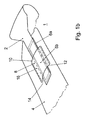
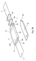
- FIG 4a shows a fourth embodiment of a Velcro connecting assembly according to the invention, with the parts corresponding to the Figures 1-3 having the same reference numerals.
- the Velcro of the first type 6a of the first Velcro connection is provided on top of the second part 4 while the Velcro of the second type 6b of the first Velcro connection is provided at the lower side of the first part 2.
- the first part 2 and the second part 4 are part of a hoisting belt.
- the covering 8 is provided around the second part so that it is freely slidable in the direction of the arrow Q.
- an upper side of the first part 2 is provided with the Velcro of the second type 32b of the second Velcro connection.
- An inside of the covering 8 is provided with a Velcro of the first type 32a of the second Velcro connection 32a, 32b. This is the inside that is present above the second part 4.
- the Velcro of the first type 6a is connected to the Velcro of the second type 6b.
- the key 20 is then laid on top of the first part 2, such that the key 18 covers the Velcro of the second type 32b (Fig. 4b).
- the covering 8 is then slid over the key 18 and thus over the first part 2. All this is done such that the key 18 is present between the Velcro of the first type 32a and the Velcro of the second type 32b.
- the key 18 can also be inserted into the opening 12, so that the key 18 completely extends through the covering and is present above the second part 4.
- the covering 8 can then be slid over the first Velcro connection 6a, 6b together with the key, after which the key 18 is removed by, for instance, pulling it from the first opening or the second opening 12. After this, the second Velcro connection 32a, 32b is established..
- the covering 8 can also be provided so that it is slidable over the first part.
- the covering 8 is and remains provided over the first part and slides over the first part over the Velcro connection 6a, 6b.
- the Velcro of the second type 32b is provided on the lower side of the second part 4 (Fig. 5).
- the Velcro of the first type 6a and the Velcro of the second type 32b are present on both sides of the second part 4.
- the Velcro of the first type 32a is provided on the inside of the covering 8 which extends below the second part 4.
- the Velcro of the first type 32a can consist of hooks, or loops, while the Velcro of the second type 32b consists of loops, or hooks.
- the key can be laid on top of the Velcro of the second type 32b before the covering8 is slid over the Velcro connection 6a, 6b, after which the covering 8 is slid over the key and thus over the Velcro connection 6a, 6b.
- the key is placed on the first part, after which the first part and the key together are slid into the covering to establish the Velcro connection 6a, 6b.
- such a method is also applicable in the arrangement of Figure 1.
- the key 18 can be positioned below the first part 2, after which the first part and the key 18 are then slid into the covering 8 together.
- the opening 12 of the covering can be closed.
- these openings remain open so that it is clear that the first part 2 is sufficiently deeply and preferably even completely slid into the covering, and even partly sticks out of the opening 12.
Landscapes
- Purses, Travelling Bags, Baskets, Or Suitcases (AREA)
- Slide Fasteners, Snap Fasteners, And Hook Fasteners (AREA)
- Details Of Garments (AREA)
- Orthopedics, Nursing, And Contraception (AREA)
- Materials For Medical Uses (AREA)
- Sealing Battery Cases Or Jackets (AREA)
- Hooks, Suction Cups, And Attachment By Adhesive Means (AREA)
- Infusion, Injection, And Reservoir Apparatuses (AREA)
Claims (24)
- System (1), das mit einer Klettverbindungsanordnung ausgestattet ist, die mit einem ersten Teil (2) und einem zweiten Teil (4, 8) ausgestattet ist, die unmittelbar lösbar mit Hilfe einer ersten Klettverbindung (6a, 6b, 32a, 32b) verbunden sind, wobei die Klettverbindungsanordnung ferner mit einer kanalförmigen Abdeckung (8, 4) mit mindestens einer Öffnung (10, 12) ausgestattet ist, wobei sich das erste Teil (2) von außerhalb der Abdeckung (8, 4) durch die mindestens eine Öffnung in die Abdeckung (8) erstreckt und die erste Klettverbindung (6a, 6b, 32a, 32b) zumindest teilweise in der Abdeckung (8) aufgenommen ist, wobei die Abdeckung die erste Klettverbindung (6a, 6b, 32a, 32b) dicht abdeckt, so dass die erste Klettverbindung nicht geeignet ist, um manuell gelöst zu werden, dadurch gekennzeichnet, dass das System ferner mit einem starren Löse/Schließelement (18) ausgestattet ist, wobei das Löse/Schließelement (18) von spatelförmiger Ausgestaltung ist und eine Breite hat, die geeignet ist, um in die Abdeckung zu gleiten, um die erste Klettverbindung zu öffnen.
- System nach Anspruch 1, dadurch gekennzeichnet, dass die erste Klettverbindung mit einem Klettelement eines ersten Typs (6a) und einem Klettelement eines zweiten Typs (6b) ausgestattet ist, wobei das Klettelement des ersten Typs (6a) an dem ersten Teil (2) befestigt ist und das Klettelement des zweiten Typs (6b) an einer Innenseite der Abdeckung (8) befestigt ist, wobei die Abdeckung (8, 4) an dem zweiten Teil (4, 8) befestigt ist oder einen Teil von diesem bildet.
- System nach Anspruch 2, dadurch gekennzeichnet, dass die Abdeckung (8, 4) durch einen Teil des zweiten Teils und ein drittes Teil (26) gebildet wird, das fest an dem zweiten Teil befestigt ist.
- System nach Anspruch 2 oder 3, dadurch gekennzeichnet, dass das Klettelement des zweiten Typs (6b) an dem dritten Teil (26) befestigt ist.
- System nach Anspruch 2 oder 3, dadurch gekennzeichnet, dass das Klettelement des zweiten Typs an dem zweiten Teil (4, 8) befestigt ist.
- System nach Anspruch 1, dadurch gekennzeichnet, dass das erste Teil (2) von streifenförmiger Ausgestaltung ist, wobei ein Umlenkteil (24), der an ein Ende des ersten Teils angrenzt, über ein Kontaktteil (26) des ersten Teils umgelenkt ist, der an den Umlenkteil angrenzt, so dass eine Schlaufe (28) ausgebildet ist, mit der das zweite Teil verbunden ist, wobei der Umlenkteil (24) und der Kontaktteil (26) lösbar durch die erste Klettverbindung (6a, 6b) verbunden sind und wobei der Umlenkteil und der Kontaktteil durch die Abdeckung abgedeckt sind. (Figur 3)
- System nach Anspruch 6, dadurch gekennzeichnet, dass die erste Klettverbindung (6a, 6b) mit einem Klettelement des ersten Typs (6a) und einem Klettelement des zweiten Typs (6b) ausgestattet ist, wobei das Klettelement des ersten Typs an dem Kontaktteil (26) befestigt ist und das Klettelement des zweiten Typs an dem Umlenkteil (24) befestigt ist.
- System nach Anspruch 6 oder 7, dadurch gekennzeichnet, dass die Klettverbindungsanordnung ferner mit einer zweiten Klettverbindung (32a, 32b) ausgestattet ist, die eine Innenseite der Abdeckung mit dem ersten Teil verbindet.
- System nach Anspruch 8, dadurch gekennzeichnet, dass die zweite Klettverbindung (32a, 32b) die Innenseite der Abdeckung (8) und eine Außenseite des Umlenkteils (24) verbindet, wobei die erste und die zweite Klettverbindung an beiden Seiten des Umlenkteils (24) vorhanden sind.
- System nach Anspruch 9, dadurch gekennzeichnet, dass die zweite Klettverbindung (32a, 32b) mit einem Klettelement des ersten Typs (32a) und einem Klettelement des zweiten Typs (32b) ausgestattet ist, wobei das Klettelement des ersten Typs und das Klettelement des zweiten Typs an der Innenseite der Abdeckung (8) oder dem Umlenkteil (24) beziehungsweise dem Umlenkteil oder der Innenseite der Abdeckung befestigt sind.
- System nach Anspruch 8, dadurch gekennzeichnet, dass die zweite Klettverbindung (32a, 32b) die Innenseite der Abdeckung und eine Außenseite des Kontaktteils verbindet, wobei die erste und die zweite Klettverbindung an beiden Seiten des Kontaktteils (26) vorhanden sind.
- System nach Anspruch 11, dadurch gekennzeichnet, dass die zweite Klettverbindung (32a, 32b) mit einem Klettelement des ersten Typs (32a) und einem Klettelement des zweiten Typs (32b) ausgestattet ist, wobei das Klettelement des ersten Typs und das Klettelement des zweiten Typs an der Innenseite der Abdeckung (8) oder dem Kontaktteil (26) beziehungsweise dem Kontaktteil (26) oder der Innenseite der Abdeckung (8) befestigt sind.
- System nach Anspruch 1, dadurch gekennzeichnet, dass die Klettverbindungsanordnung ferner mit einer zweiten Klettverbindung (32a, 32b) ausgestattet ist, die eine Innenseite der Abdeckung (8) mit dem ersten Teil (2) verbindet, wobei die erste und die zweite Klettverbindung an beiden Seiten des ersten Teils (2) vorhanden sind. (Figur 4)
- System nach Anspruch 13, dadurch gekennzeichnet, dass die zweite Klettverbindung (32a, 32b) mit einem Klettelement des ersten Typs und einem Klettelement des zweiten Typs ausgestattet ist, wobei das Klettelement des ersten Typs und das Klettelement des zweiten Typs an der Innenseite der Abdeckung (8) oder dem ersten Teil (2) beziehungsweise dem ersten Teil (2) oder der Innenseite der Abdeckung (8) befestigt sind.
- System nach Anspruch 1, dadurch gekennzeichnet, dass die Klettverbindungsanordnung ferner mit einer zweiten Klettverbindung (32a, 32b) ausgestattet ist, die eine Innenseite der Abdeckung (8) mit dem zweiten Teil (4) verbindet, wobei die erste und die zweite Klettverbindung an beiden Seiten des zweiten Teils (4) vorhanden sind. (Figur 5)
- System nach Anspruch 15, dadurch gekennzeichnet, dass die zweite Klettverbindung (32a, 32b) mit einem Klettelement des erste Typs (32a) und einem Klettelement des zweiten Typs (32b) ausgestattet ist, wobei das Klettelement des ersten Typs und das Klettelement des zweiten Typs an der Innenseite der Abdeckung (8) oder dem zweiten Teil (4) beziehungsweise dem zweiten Teil (4) oder der Innenseite der Abdeckung (8) befestigt sind.
- System nach einem der Ansprüche 6 bis 11, dadurch gekennzeichnet, dass die Abdeckung (8) ferner mit einer zweiten Öffnung (12) ausgestattet ist, wobei sich das erste oder das zweite Teil (2, 4) von außerhalb der Abdeckung durch die zweite Öffnung (12) in die Abdeckung erstreckt.
- System nach einem der vorhergehenden Ansprüche, dadurch gekennzeichnet, dass das erste Teil (2) von streifenförmiger Ausgestaltung ist.
- System nach einem der vorhergehenden Ansprüche, dadurch gekennzeichnet, dass das zweite Teil (4) von streifenförmiger Ausgestaltung ist.
- System nach einem der vorhergehenden Ansprüche, dadurch gekennzeichnet, dass das erste Teil (2) aus einem flexiblen Material hergestellt ist, wie etwa einem Textil oder einem Kunststoff.
- System nach einem der vorhergehenden Ansprüche, dadurch gekennzeichnet, dass das zweite Teil (4) aus einem flexiblen Material hergestellt ist, wie etwa einem Textil oder einem Kunststoff.
- System nach einem der vorhergehenden Ansprüche, dadurch gekennzeichnet, dass die Abdeckung (8) aus einem flexiblen Material hergestellt ist, wie etwa einem Textil oder einem Kunststoff.
- Gürtel mit einem System (1) nach einem der vorhergehenden Ansprüche 1 bis 33, wobei das erste und das zweite Teil (2, 4) jeweils Teil der Enden des Gürtels sind.
- Förderband, das mit einem System (1) nach einem der vorhergehenden Ansprüche 1 bis 22 ausgestattet ist, wobei das erste und das zweite Teil (2, 4) jeweils Teil der Enden des Förderbandes sind.
Applications Claiming Priority (3)
| Application Number | Priority Date | Filing Date | Title |
|---|---|---|---|
| NL1020414 | 2002-04-17 | ||
| NL1020414A NL1020414C2 (nl) | 2002-04-17 | 2002-04-17 | Klittenbandverbindingssamenstel. |
| PCT/NL2003/000290 WO2003086131A1 (en) | 2002-04-17 | 2003-04-17 | Hook and loop fastener assembly |
Publications (2)
| Publication Number | Publication Date |
|---|---|
| EP1494559A1 EP1494559A1 (de) | 2005-01-12 |
| EP1494559B1 true EP1494559B1 (de) | 2007-08-01 |
Family
ID=29244988
Family Applications (1)
| Application Number | Title | Priority Date | Filing Date |
|---|---|---|---|
| EP03725868A Expired - Lifetime EP1494559B1 (de) | 2002-04-17 | 2003-04-17 | Haftverschlussanordnung |
Country Status (6)
| Country | Link |
|---|---|
| EP (1) | EP1494559B1 (de) |
| AT (1) | ATE368396T1 (de) |
| AU (1) | AU2003228131A1 (de) |
| DE (1) | DE60315277T2 (de) |
| NL (1) | NL1020414C2 (de) |
| WO (1) | WO2003086131A1 (de) |
Families Citing this family (1)
| Publication number | Priority date | Publication date | Assignee | Title |
|---|---|---|---|---|
| WO2015160975A2 (en) | 2014-04-16 | 2015-10-22 | Infinity Pharmaceuticals, Inc. | Combination therapies |
Family Cites Families (5)
| Publication number | Priority date | Publication date | Assignee | Title |
|---|---|---|---|---|
| GB1103471A (en) * | 1965-03-02 | 1968-02-14 | Selectus Ltd | Improvements in or relating to the securement of faster members |
| US4054952A (en) * | 1976-04-13 | 1977-10-25 | The Kendall Company | Belt assembly |
| GB2237062A (en) * | 1989-10-18 | 1991-04-24 | Harry Tew | Securing strap |
| FR2764783B1 (fr) * | 1997-06-23 | 1999-09-10 | Europ De Dev Ind Comp | Attache en boucle, notamment pour brelage, ceinturon et ceinture |
| US6449815B1 (en) * | 2001-01-12 | 2002-09-17 | Karmicheal Spiller | Adjustable strap assembly |
-
2002
- 2002-04-17 NL NL1020414A patent/NL1020414C2/nl not_active IP Right Cessation
-
2003
- 2003-04-17 AT AT03725868T patent/ATE368396T1/de not_active IP Right Cessation
- 2003-04-17 DE DE60315277T patent/DE60315277T2/de not_active Expired - Lifetime
- 2003-04-17 EP EP03725868A patent/EP1494559B1/de not_active Expired - Lifetime
- 2003-04-17 AU AU2003228131A patent/AU2003228131A1/en not_active Abandoned
- 2003-04-17 WO PCT/NL2003/000290 patent/WO2003086131A1/en not_active Ceased
Non-Patent Citations (1)
| Title |
|---|
| None * |
Also Published As
| Publication number | Publication date |
|---|---|
| DE60315277D1 (de) | 2007-09-13 |
| NL1020414C2 (nl) | 2003-10-20 |
| AU2003228131A1 (en) | 2003-10-27 |
| WO2003086131A1 (en) | 2003-10-23 |
| ATE368396T1 (de) | 2007-08-15 |
| EP1494559A1 (de) | 2005-01-12 |
| DE60315277T2 (de) | 2008-04-17 |
Similar Documents
| Publication | Publication Date | Title |
|---|---|---|
| EP1495459B1 (de) | Informationsband | |
| US4826193A (en) | Wheel chair restraint | |
| US5279386A (en) | Rescue harness | |
| EP0567530B1 (de) | Kindertrageschultergeschirr | |
| KR970009504B1 (ko) | 그네용 안전 바아 조립체 | |
| US5584105A (en) | Quick disconnect buckle | |
| US20070271744A1 (en) | Hook and loop fastener assembly | |
| CA2666734C (en) | Single waistband belt system convertible between a sit harness and quick release utility belt | |
| US4860560A (en) | Restraining device | |
| JP3161739U (ja) | カーテン吊下具 | |
| US6644597B1 (en) | Canopy quick release device for parachutes | |
| AU2001252820B2 (en) | A baby carrying harness | |
| US5032104A (en) | Front opening brassiere for easy access and removal by a handicapped person | |
| EP1606141A1 (de) | Kindersitzüberzug | |
| EP0917837A3 (de) | Trennbarer unterer Endanschlag für Reissverschlüsse | |
| AU2001252820A1 (en) | A baby carrying harness | |
| US20030150088A1 (en) | Quick-release buckle | |
| EP2305196A1 (de) | Patientengurtsystem für ein Notbett | |
| EP1494559B1 (de) | Haftverschlussanordnung | |
| EP1990035B1 (de) | Matratze | |
| EP1647249B1 (de) | Befestigungsvorrichtung | |
| JP4509694B2 (ja) | 折畳み式サイドレール用カバー | |
| CN108741286A (zh) | 一种多功能安全行装 | |
| EP4301176B1 (de) | Verriegelbarer reissverschluss und damit assoziierte kleidungsstücke | |
| CN211559502U (zh) | 便于人为控制分离的防儿童走失牵引带 |
Legal Events
| Date | Code | Title | Description |
|---|---|---|---|
| PUAI | Public reference made under article 153(3) epc to a published international application that has entered the european phase |
Free format text: ORIGINAL CODE: 0009012 |
|
| 17P | Request for examination filed |
Effective date: 20041103 |
|
| AK | Designated contracting states |
Kind code of ref document: A1 Designated state(s): AT BE BG CH CY CZ DE DK EE ES FI FR GB GR HU IE IT LI LU MC NL PT RO SE SI SK TR |
|
| AX | Request for extension of the european patent |
Extension state: AL LT LV MK |
|
| GRAP | Despatch of communication of intention to grant a patent |
Free format text: ORIGINAL CODE: EPIDOSNIGR1 |
|
| GRAS | Grant fee paid |
Free format text: ORIGINAL CODE: EPIDOSNIGR3 |
|
| GRAA | (expected) grant |
Free format text: ORIGINAL CODE: 0009210 |
|
| AK | Designated contracting states |
Kind code of ref document: B1 Designated state(s): AT BE BG CH CY CZ DE DK EE ES FI FR GB GR HU IE IT LI LU MC NL PT RO SE SI SK TR |
|
| REG | Reference to a national code |
Ref country code: GB Ref legal event code: FG4D |
|
| REG | Reference to a national code |
Ref country code: CH Ref legal event code: EP |
|
| REG | Reference to a national code |
Ref country code: IE Ref legal event code: FG4D |
|
| REF | Corresponds to: |
Ref document number: 60315277 Country of ref document: DE Date of ref document: 20070913 Kind code of ref document: P |
|
| REG | Reference to a national code |
Ref country code: SE Ref legal event code: TRGR |
|
| PG25 | Lapsed in a contracting state [announced via postgrant information from national office to epo] |
Ref country code: FI Free format text: LAPSE BECAUSE OF FAILURE TO SUBMIT A TRANSLATION OF THE DESCRIPTION OR TO PAY THE FEE WITHIN THE PRESCRIBED TIME-LIMIT Effective date: 20070801 Ref country code: BG Free format text: LAPSE BECAUSE OF FAILURE TO SUBMIT A TRANSLATION OF THE DESCRIPTION OR TO PAY THE FEE WITHIN THE PRESCRIBED TIME-LIMIT Effective date: 20071101 Ref country code: ES Free format text: LAPSE BECAUSE OF FAILURE TO SUBMIT A TRANSLATION OF THE DESCRIPTION OR TO PAY THE FEE WITHIN THE PRESCRIBED TIME-LIMIT Effective date: 20071112 |
|
| REG | Reference to a national code |
Ref country code: CH Ref legal event code: PL |
|
| PG25 | Lapsed in a contracting state [announced via postgrant information from national office to epo] |
Ref country code: LI Free format text: LAPSE BECAUSE OF FAILURE TO SUBMIT A TRANSLATION OF THE DESCRIPTION OR TO PAY THE FEE WITHIN THE PRESCRIBED TIME-LIMIT Effective date: 20070801 Ref country code: CH Free format text: LAPSE BECAUSE OF FAILURE TO SUBMIT A TRANSLATION OF THE DESCRIPTION OR TO PAY THE FEE WITHIN THE PRESCRIBED TIME-LIMIT Effective date: 20070801 Ref country code: AT Free format text: LAPSE BECAUSE OF FAILURE TO SUBMIT A TRANSLATION OF THE DESCRIPTION OR TO PAY THE FEE WITHIN THE PRESCRIBED TIME-LIMIT Effective date: 20070801 |
|
| EN | Fr: translation not filed | ||
| PG25 | Lapsed in a contracting state [announced via postgrant information from national office to epo] |
Ref country code: BE Free format text: LAPSE BECAUSE OF FAILURE TO SUBMIT A TRANSLATION OF THE DESCRIPTION OR TO PAY THE FEE WITHIN THE PRESCRIBED TIME-LIMIT Effective date: 20070801 |
|
| PG25 | Lapsed in a contracting state [announced via postgrant information from national office to epo] |
Ref country code: DK Free format text: LAPSE BECAUSE OF FAILURE TO SUBMIT A TRANSLATION OF THE DESCRIPTION OR TO PAY THE FEE WITHIN THE PRESCRIBED TIME-LIMIT Effective date: 20070801 Ref country code: GR Free format text: LAPSE BECAUSE OF FAILURE TO SUBMIT A TRANSLATION OF THE DESCRIPTION OR TO PAY THE FEE WITHIN THE PRESCRIBED TIME-LIMIT Effective date: 20071102 |
|
| PG25 | Lapsed in a contracting state [announced via postgrant information from national office to epo] |
Ref country code: PT Free format text: LAPSE BECAUSE OF FAILURE TO SUBMIT A TRANSLATION OF THE DESCRIPTION OR TO PAY THE FEE WITHIN THE PRESCRIBED TIME-LIMIT Effective date: 20080102 Ref country code: SK Free format text: LAPSE BECAUSE OF FAILURE TO SUBMIT A TRANSLATION OF THE DESCRIPTION OR TO PAY THE FEE WITHIN THE PRESCRIBED TIME-LIMIT Effective date: 20070801 Ref country code: CZ Free format text: LAPSE BECAUSE OF FAILURE TO SUBMIT A TRANSLATION OF THE DESCRIPTION OR TO PAY THE FEE WITHIN THE PRESCRIBED TIME-LIMIT Effective date: 20070801 |
|
| PLBE | No opposition filed within time limit |
Free format text: ORIGINAL CODE: 0009261 |
|
| STAA | Information on the status of an ep patent application or granted ep patent |
Free format text: STATUS: NO OPPOSITION FILED WITHIN TIME LIMIT |
|
| PG25 | Lapsed in a contracting state [announced via postgrant information from national office to epo] |
Ref country code: RO Free format text: LAPSE BECAUSE OF FAILURE TO SUBMIT A TRANSLATION OF THE DESCRIPTION OR TO PAY THE FEE WITHIN THE PRESCRIBED TIME-LIMIT Effective date: 20070801 |
|
| 26N | No opposition filed |
Effective date: 20080506 |
|
| PG25 | Lapsed in a contracting state [announced via postgrant information from national office to epo] |
Ref country code: FR Free format text: LAPSE BECAUSE OF FAILURE TO SUBMIT A TRANSLATION OF THE DESCRIPTION OR TO PAY THE FEE WITHIN THE PRESCRIBED TIME-LIMIT Effective date: 20080328 |
|
| PG25 | Lapsed in a contracting state [announced via postgrant information from national office to epo] |
Ref country code: MC Free format text: LAPSE BECAUSE OF NON-PAYMENT OF DUE FEES Effective date: 20080430 |
|
| PG25 | Lapsed in a contracting state [announced via postgrant information from national office to epo] |
Ref country code: EE Free format text: LAPSE BECAUSE OF FAILURE TO SUBMIT A TRANSLATION OF THE DESCRIPTION OR TO PAY THE FEE WITHIN THE PRESCRIBED TIME-LIMIT Effective date: 20070801 |
|
| PG25 | Lapsed in a contracting state [announced via postgrant information from national office to epo] |
Ref country code: IE Free format text: LAPSE BECAUSE OF NON-PAYMENT OF DUE FEES Effective date: 20080417 |
|
| PG25 | Lapsed in a contracting state [announced via postgrant information from national office to epo] |
Ref country code: SI Free format text: LAPSE BECAUSE OF FAILURE TO SUBMIT A TRANSLATION OF THE DESCRIPTION OR TO PAY THE FEE WITHIN THE PRESCRIBED TIME-LIMIT Effective date: 20070801 |
|
| PG25 | Lapsed in a contracting state [announced via postgrant information from national office to epo] |
Ref country code: CY Free format text: LAPSE BECAUSE OF FAILURE TO SUBMIT A TRANSLATION OF THE DESCRIPTION OR TO PAY THE FEE WITHIN THE PRESCRIBED TIME-LIMIT Effective date: 20070801 |
|
| PG25 | Lapsed in a contracting state [announced via postgrant information from national office to epo] |
Ref country code: LU Free format text: LAPSE BECAUSE OF NON-PAYMENT OF DUE FEES Effective date: 20080417 Ref country code: HU Free format text: LAPSE BECAUSE OF FAILURE TO SUBMIT A TRANSLATION OF THE DESCRIPTION OR TO PAY THE FEE WITHIN THE PRESCRIBED TIME-LIMIT Effective date: 20080202 |
|
| PG25 | Lapsed in a contracting state [announced via postgrant information from national office to epo] |
Ref country code: TR Free format text: LAPSE BECAUSE OF FAILURE TO SUBMIT A TRANSLATION OF THE DESCRIPTION OR TO PAY THE FEE WITHIN THE PRESCRIBED TIME-LIMIT Effective date: 20070801 |
|
| PGFP | Annual fee paid to national office [announced via postgrant information from national office to epo] |
Ref country code: DE Payment date: 20100423 Year of fee payment: 8 Ref country code: NL Payment date: 20100415 Year of fee payment: 8 |
|
| PGFP | Annual fee paid to national office [announced via postgrant information from national office to epo] |
Ref country code: GB Payment date: 20100420 Year of fee payment: 8 Ref country code: SE Payment date: 20100422 Year of fee payment: 8 |
|
| PG25 | Lapsed in a contracting state [announced via postgrant information from national office to epo] |
Ref country code: IT Free format text: LAPSE BECAUSE OF NON-PAYMENT OF DUE FEES Effective date: 20080430 |
|
| REG | Reference to a national code |
Ref country code: NL Ref legal event code: V1 Effective date: 20111101 |
|
| REG | Reference to a national code |
Ref country code: SE Ref legal event code: EUG |
|
| GBPC | Gb: european patent ceased through non-payment of renewal fee |
Effective date: 20110417 |
|
| PG25 | Lapsed in a contracting state [announced via postgrant information from national office to epo] |
Ref country code: NL Free format text: LAPSE BECAUSE OF NON-PAYMENT OF DUE FEES Effective date: 20111101 Ref country code: DE Free format text: LAPSE BECAUSE OF NON-PAYMENT OF DUE FEES Effective date: 20111101 |
|
| PG25 | Lapsed in a contracting state [announced via postgrant information from national office to epo] |
Ref country code: GB Free format text: LAPSE BECAUSE OF NON-PAYMENT OF DUE FEES Effective date: 20110417 |
|
| REG | Reference to a national code |
Ref country code: DE Ref legal event code: R119 Ref document number: 60315277 Country of ref document: DE Effective date: 20111101 |
|
| PG25 | Lapsed in a contracting state [announced via postgrant information from national office to epo] |
Ref country code: SE Free format text: LAPSE BECAUSE OF NON-PAYMENT OF DUE FEES Effective date: 20110418 |