EP1494567B1 - Appareil permettant la mouture de matieres, notamment d'epices ou de cereales - Google Patents
Appareil permettant la mouture de matieres, notamment d'epices ou de cereales Download PDFInfo
- Publication number
- EP1494567B1 EP1494567B1 EP03714276A EP03714276A EP1494567B1 EP 1494567 B1 EP1494567 B1 EP 1494567B1 EP 03714276 A EP03714276 A EP 03714276A EP 03714276 A EP03714276 A EP 03714276A EP 1494567 B1 EP1494567 B1 EP 1494567B1
- Authority
- EP
- European Patent Office
- Prior art keywords
- grinding
- bit
- lever
- grinder
- grinder bit
- Prior art date
- Legal status (The legal status is an assumption and is not a legal conclusion. Google has not performed a legal analysis and makes no representation as to the accuracy of the status listed.)
- Expired - Lifetime
Links
- 239000000463 material Substances 0.000 title claims abstract description 27
- 235000013599 spices Nutrition 0.000 title claims abstract description 7
- 230000007246 mechanism Effects 0.000 claims abstract description 51
- 230000033001 locomotion Effects 0.000 claims abstract description 10
- 230000007935 neutral effect Effects 0.000 claims description 6
- 239000002245 particle Substances 0.000 abstract description 2
- 230000005540 biological transmission Effects 0.000 description 3
- 235000002566 Capsicum Nutrition 0.000 description 2
- 239000006002 Pepper Substances 0.000 description 2
- 241000722363 Piper Species 0.000 description 2
- 235000016761 Piper aduncum Nutrition 0.000 description 2
- 235000017804 Piper guineense Nutrition 0.000 description 2
- 235000008184 Piper nigrum Nutrition 0.000 description 2
- 230000008878 coupling Effects 0.000 description 2
- 238000010168 coupling process Methods 0.000 description 2
- 238000005859 coupling reaction Methods 0.000 description 2
- 238000004519 manufacturing process Methods 0.000 description 2
- 150000003839 salts Chemical class 0.000 description 2
- 230000006835 compression Effects 0.000 description 1
- 238000007906 compression Methods 0.000 description 1
- 230000001419 dependent effect Effects 0.000 description 1
- 210000003811 finger Anatomy 0.000 description 1
- 239000012530 fluid Substances 0.000 description 1
- 235000013305 food Nutrition 0.000 description 1
- 238000012986 modification Methods 0.000 description 1
- 230000004048 modification Effects 0.000 description 1
- 238000002360 preparation method Methods 0.000 description 1
- 210000003813 thumb Anatomy 0.000 description 1
Images

Classifications
-
- A—HUMAN NECESSITIES
- A47—FURNITURE; DOMESTIC ARTICLES OR APPLIANCES; COFFEE MILLS; SPICE MILLS; SUCTION CLEANERS IN GENERAL
- A47J—KITCHEN EQUIPMENT; COFFEE MILLS; SPICE MILLS; APPARATUS FOR MAKING BEVERAGES
- A47J42/00—Coffee mills; Spice mills
- A47J42/38—Parts or details
- A47J42/46—Driving mechanisms; Coupling to drives
-
- A—HUMAN NECESSITIES
- A47—FURNITURE; DOMESTIC ARTICLES OR APPLIANCES; COFFEE MILLS; SPICE MILLS; SUCTION CLEANERS IN GENERAL
- A47J—KITCHEN EQUIPMENT; COFFEE MILLS; SPICE MILLS; APPARATUS FOR MAKING BEVERAGES
- A47J42/00—Coffee mills; Spice mills
- A47J42/32—Coffee mills; Spice mills with other grinding or pulverising members
- A47J42/34—Coffee mills; Spice mills with other grinding or pulverising members hand driven
Definitions
- This invention is generally related to grinding mechanisms, and more particularly to grinders or mills for grinding materials, such as spices and grain.
- Mills for grinding materials such as spices and grains are common household items.
- pepper mills are ubiquitous in households and restaurants.
- Such mills generally include a housing or body which presents an attractive outward appearance, and which forms a chamber or reservoir for holding a material (e.g., peppercorns) to be ground.
- the body also typically encloses a grinding mechanism in fluid communication with the chamber, the grinding mechanism grinding the material and dispensing the ground material through an opening or exit in the bottom of the body.
- the grinding mechanism typically includes an actuator (e.g. , crank arm, operating lever), a grinding bit, an engagement surface for cooperating with the grinding bit to grind the material therebetween, and a transmission drivingly coupling the actuator to the grinding bit.
- the body will form a second chamber, separate from the first chamber, for holding a material that does not requiring grinding (e.g., salt).
- mills are hand operated and may be used by chefs or cooks in the preparation of food, or by servers and/or diners at dining tables.
- Many mills have a crank arm which is turned continuously and unidirectionally (e.g. , clockwise or counterclockwise) with one hand of the user, while the other hand holds the mill in a generally vertical direction such that the ground material drops out of the bottom.
- Other mills have an operating lever which is reciprocatingly operated ( i.e., bidirectionally) with the fingers or thumb of the hand holding the mill.
- the grinding mechanisms fall into two categories, rotary mechanisms and linear mechanisms.
- Many rotary mechanisms are driven by turning a crank arm directly connected to a drive shaft of the grinding mechanism, which in turn is directly connected to the grinding bit.
- the crank arm, drive shaft and grinding bit each rotate about respective axes or rotation, the axes being parallel to each other, or even collinear.
- a number of rotary mechanisms are driven by reciprocating movement of an operating lever.
- Such rotary mechanisms include a grinding bit axially mounted on a drive shaft, and transmission means in the form of gears for translating the reciprocating motion of the operating lever into rotation of the drive shaft for driving the grinding bit.
- the axes of rotation of the drive shaft and grinding bits are parallel or even collinear.
- Linear grinding mechanisms rely on linear movement of the grinding bit to grind the material.
- linear mechanisms employ the axial translation of a transmission element, such as a rack, to produce the linear translation of the grinding bit.
- Most grinders also include mechanisms for adjusting the space between the grinding bit and the engagement surface to allow the user to select a desired grain size.
- the grinding bits are typically conical and having a uniform set of teeth around the periphery of the cone or truncated cone.
- the space between the engagement surface and the grinding bit may be adjusted by translating the conical grinding bit along its longitudinal axis with respect to the engagement surface.
- the grinding bit typically takes the form of a straight or beveled surface having a set of uniform teeth.
- the space between the engagement surface and the grinding bit is adjusted by translating the grinding bit either toward or away from the engagement surface.
- FR-A-777375 discloses a grinding mechanism for a mill according to the preamble of independent claim 1.
- the object of the present invention is achieved by a grinding mechanism according to independent claim 1.
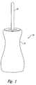
- Figure 1 is a side, top isometric view of a mill for grinding material such as spices or grain.
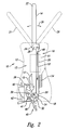
- Figure 2 is a cross-sectional view of the mill of Figure 1, taken through the longitudinal axis of a body of the mill, showing a grinding mechanism including a lever, linkage, grinding bit, engagement member having an engagement surface, and cam, and also showing material to be ground within a chamber formed by the body and ground material exiting the mill.
- a grinding mechanism including a lever, linkage, grinding bit, engagement member having an engagement surface, and cam, and also showing material to be ground within a chamber formed by the body and ground material exiting the mill.
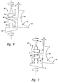
- Figure 3 is a side elevational view of an exemplary grinding bit including a set of grinding protuberances in the form of a gradated set of teeth.
- Figure 4 is an isometric view of an exemplary grinding bit including a set of grinding protuberances in the form of a knurled gradated surface.
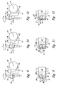
- Figure 6 is a side elevational view of a first adjustment mechanism including a set of cams having opposed cam surfaces, rotated to pivotally position the engagement member in a first position.
- Figure 7 is a side elevational view of the first adjustment mechanism of Figure 6 illustrating the cams rotated 180 degrees from that of Figure 6, to pivotally position the engagement member in a second position.
- Figure 8 is a side elevational view of a second adjustment mechanism including a cam rotated to pivotally position the engagement member in a first position.
- Figure 9 is a top plan view of the second adjustment mechanism, the cam rotated to pivotally position the engagement member in the first position of Figure 8.
- Figure 10 is a side elevational view of the second adjustment mechanism of Figure 8, illustrating the cam rotated from that of Figure 8, to pivotally position the engagement member in a second position.
- Figure 11 is a top plan view of the second adjustment mechanism, the cam rotated to pivotally position the engagement member in the second position of Figure 10.
- Figure 12 is a side elevational view of the second adjustment mechanism of Figure 8, illustrating the cam further rotated from that of Figure 10, to pivotally position the engagement member in a third position.
- Figure 13 is a top plan view of the second adjustment mechanism, the cam rotated to pivotally position the engagement member in the third position of Figure 13.
- Figure 1 shows a grinder or mill 10 for grinding a material such as spices (e.g., pepper, salt) or grains.
- the mill 10 includes a body 12 and a lever 14 at least a portion of which is accessible from outside the body 12.
- the body 12 may take the form of a body of revolution, although any other aesthetically pleasing shape may be employed.
- FIG 2 shows a grinding mechanism 16 of the mill 10.
- the grinding mechanism 16 includes the lever 14, a grinding bit 18, and a linkage 20 drivingly coupling the lever 14 to the grinding bit 18.
- the lever 14 includes a first end 22 and a second end 24, and is mounted proximate the second end 24 for reciprocating pivotal movement illustrated by double-headed arrow 26 about a lever axis 28.
- the lever 14 has a neutral position, illustrated in solid line in Figure 2.
- the lever 14 can be reciprocatingly moved between the neutral position and one of a pair of fully displaced positions 29, 31, illustrated in broken line in Figure 2.
- the lever 14 can be reciprocatingly moved between the pair of fully displaced positions.
- the lever 14 can be operated using one hand, while the other hand holds the body 12 of the mill 10.
- the grinding bit 18 may take the form of a wheel or cylinder mounted for rotation, illustrated by double-headed arrow 30, about a grinding bit rotation axis 32.
- the lever axis 28 and grinding bit rotation axis 32 are parallel within acceptable manufacturing tolerances.
- the illustrated grinding bit is cylindrical, in contrast to the conical grinding bits typically employed in rotary grind mechanisms, and may take the form of a right cylinder.
- the grinding bit 18 includes an edge or periphery 34.
- the grinding bit 18 also includes one or more grinding protuberances, discussed in detail below with reference to Figures 3,4.
- the grinding bit 18 cooperates with an engagement surface 38 of an engagement member 40 such as a shear block, the engagement surface 38 being opposed to, and spaced from, the grinding bit 18 to receive and grind a material to be ground 15 therebetween.
- the illustrated engagement surface 38 is arcuate proximate at least one end 43 thereof, the arcuate portion having a radius of curvature complementing a radius of curvature of the periphery 34 of the grinding bit 18.
- the engagement surface 38 of the grinding bit 18 can be formed without the arcuate portion, without deviating from of the invention.
- the material to be ground 15 may be stored in a chamber 13 formed by the body 12 of the mill 10.
- the flow of material to be ground 15 from the chamber 13 to the grinding bit 18 is illustrated by arrow 17.
- the ground material 45 exits the mill 10 via an exit aperture 46, typically in the bottom of the body 12.
- the space between the grinding bit 18 and the engagement surface 38 is adjustable by way of a cam mechanism 42, which pivots the engagement member 40 about and adjustment axis 41, as illustrated and discussed in more detail below with reference to Figures 6-11.
- the linkage 20 has a first end 48 and a second end 50.
- the first end 48 of the linkage 20 is pivotally coupled to the second end 24 of lever 14, spaced from the lever axis 28 to gain mechanical advantage.
- the second end 50 of the linkage 20 is pivotally coupled to the grinding bit 18, spaced from the grinding bit rotation axis 32.
- the linkage 20 translates in a linkage plane 51 illustrated by broken line box.
- the linkage plane 51 is perpendicular to the lever axis 28 and the grinding bit rotation axis 32.
- the linkage 20 may also rotate slightly, within the linkage plane 51. In contrast to typical rotary grinding mechanisms, this rotation is about an axis that is perpendicular to a longitudinal axis illustrated by double-headed arrow 52 of the linkage 20.
- the mill 10 may include an optional biasing member, such as a spring or other resilient member.
- a compression spring 54 is coupled between the body 12 and the linkage 20 to bias the lever 14 toward the neutral position from the displaced positions.
- the biasing.member may be coupled between the body 12 and the lever 14 or grinding bit 18.
- the biasing member may be coupled between various elements of the grinding mechanism 16.
- the biasing member may take the form of a coil or spiral spring coupled to the grinding bit.
- the mill 10 may omit the biasing member, relying on the user to return the lever 14 to the neutral position from one or both displaced positions.
- Figure 3 shows one embodiment of the grinding bit, having a set of grinding protuberances in the form of a set of teeth 60 on the periphery 34 of the grinding bit 18.
- the teeth 60 may be gradated between a first angular position 62 and a second angular position 64, as illustrated in Figure 3.
- the size of the teeth 60 becomes increasingly smaller as the periphery 34 is transversed between the first angular position 62 and the second angular position 64.
- each tooth 60 is successively smaller than a previous tooth as the periphery is transversed from the first to the second angular positions 62, 64, respectively.
- the teeth 60 are grouped in sections, each section having teeth 60 of a uniform size, with the section having the largest teeth 60 positioned proximate the first radial position 62 and the section having the smallest teeth 60 positioned proximate the radial position 64.
- the larger teeth 60 may be positioned toward a top of the mill 10, where the material to be ground 15 first enters the space between the grinding bit 18 and the engagement surface 38.
- the smaller teeth 60 may be positioned relatively toward the bottom of the mill 10, close to the exit aperture 46, where the ground material 45 exits the body 12 of the mill 10.
- the grinding bit 18 may employ other arrangements of teeth or grinding protuberances, although this arrangement ensures that the material 15 is successively acted upon by successively finer teeth as the particle size of the material becomes successively smaller.
- the grinding protuberances may extend completely about the periphery 34 of the grinding bit 18, for example, where such would lower the manufacturing cost of the grinding bit 18.
- Figure 4 shows another embodiment of the grinding bit 18, having a set of grinding protuberances in the form of a knurled surface 65 on the periphery 34 of the grinding bit 18.
- the knurled surface 65 may be gradated between the first and the second angular positions 62, 64, respectively.
- the knurled surface may be uniform between the angular positions 62, 64.
- the grinding bit 18 may employ other textured surfaces as the grinding protuberances, or may even omit texture in some embodiments.
- Figures 6 and 7 show a first adjustment mechanism, employing the cam 42 to pivot the engagement member 40 about the adjustment axis 41 to adjust the space between the engagement surface 38 and the grinding bit 18.
- the cam 42 is mounted for rotation about a cam axis 44, and includes an operating mechanism such as a lever or tab 72 accessible from outside the body 12 of the mill 10.
- the cam 42 includes at least one cam surface 74 for engaging a portion of the engagement member 40 to rotate the engagement member 40 between a first position illustrated in Figure 6 and a second position illustrated in Figure 7.
- the engagement member 40 pivots between an angle ⁇ and an angle ⁇ .
- the cam 42 includes a second cam surface 76 opposed to the first cam surface 74.
- the cam surfaces 74, 76 may be formed as beveled discs 78, 80 on a shaft 82.
- the cam surfaces 74, 76 can be arranged to form a necked region 84 therebetween to further urge the engagement member 40 into the desired position.
- Figures 8-13 show a second adjustment mechanism, employing a cam 42 to pivot the engagement member 40 about the adjustment axis 41 to adjust the space between the engagement surface 38 and the grinding bit 18.
- the cam 42 is mounted for rotation about an off-centered cam axis 44, and selectively engages portions of the engagement member 40.
- the cam 42 engages portions of a cam slot 86 formed in or through the engagement member 40.
- the second adjustment mechanism includes an operating mechanism such as a lever or tab 72 coupled to turn the cam 42 and accessible from outside the body 12 of the mill 10.
- the cam 42 may have a variety of cross-sections, including but not limited to non-circular cross-sections such as an ellipse. As illustrated in Figures 9, 11 and 13, the cross-section of the cam 42 may further include a number of flatten portions 85 that serve as detents to create a number of discrete adjustments to the spacing between the engagement surface 38 and the grinding bit 18.
- the tab 72 is in a first angular position about the cam axis 44 such that the cam 42 engages a portion 87 of the cam slot 86. As shown in Figure 8, the engagement permits the engagement member 40 to assume a first angular position about the adjustment axis 41, producing a first spacing between the engagement surface 38 and the grinding bit 18.
- the tab 72 is rotated to a second angular position about the cam axis 44 from that shown in Figure 9, such that the cam 42 engages a portion 87 of the cam slot 86.
- the engagement permits the engagement member 40 to assume a second angular position about the adjustment axis 41, producing a second spacing between the engagement surface 38 and the grinding bit 18.
- the second spacing is greater than the first spacing shown in Figure 8.
- the cam slot 86 may be tapered or include a filet or rounded edges to provide sufficient clearance for the engagement ember to rotate about the adjustment axis.
- the tab 72 is further rotated to a third angular position about the cam axis 44 from that shown in Figure 11, such that the cam 42 engages a portion 87 of the cam slot 86.
- the engagement permits the engagement member 40 to assume a third angular position about the adjustment axis 41, producing a third spacing between the engagement surface 38 and the grinding bit 18.
- the third spacing is greater than the second spacing shown in Figure 10.
- the cross-section of the cam 42 includes flatten portions, a discrete number of adjustments will be available. Where the cross-section of the cam 42 is a smooth curve, such as an ellipse, the number of available adjustments between some maximum and minimum spacing is unlimited.
Landscapes
- Engineering & Computer Science (AREA)
- Mechanical Engineering (AREA)
- Food Science & Technology (AREA)
- Crushing And Grinding (AREA)
- Disintegrating Or Milling (AREA)
- Table Devices Or Equipment (AREA)
- Crushing And Pulverization Processes (AREA)
- Noodles (AREA)
- Cereal-Derived Products (AREA)
- Seasonings (AREA)
- Adjustment And Processing Of Grains (AREA)
Claims (11)
- Mécanisme de broyage (16) pour un moulin (10) comprenant :un levier (14) monté pour un mouvement pivotal autour d'un axe du levier (28) ;une mèche de broyeur (18) présentant un périphérie de broyage (34), la mèche de broyeur (18) étant montée pour un mouvement de rotation autour d'un axe de rotation de la mèche de broyeur (32), l'axe de rotation de la mèche de broyeur (32) étant au moins approximativement parallèle à l'axe du levier (28), etune tringlerie (20) couplée de manière pivotante à la mèche de broyeur (18) et couplée de manière pivotante au levier (14) pour transférer le mouvement pivotal du levier (14) à la mèche de broyeur (18),caractérisé en ce que la mèche de broyeur (18) présente un ensemble gradué de protubérances de broyage (60, 65) le long de la périphérie (34) de celle-ci.
- Mécanisme de broyage (16) selon la revendication 1, dans lequel la tringlerie (20)est allongée et présente une première extrémité (48) et une seconde extrémité (50) opposée à la première extrémité (48), la première extrémité (48) de la tringlerie (20) étant couplée de manière pivotante au levier (14) espacé de l'axe du levier (28) et la seconde extrémité (50) de la tringlerie (20) étant couplée de manière pivotante à la mèche de broyeur (18) espacée de l'axe de rotation de la mèche de broyeur (32).
- Mécanisme de broyage (16) selon la revendication 1, dans lequel la tringlerie (20) se translate dans un plan (51) qui n'est pas parallèle à l'axe de rotation de la mèche de broyeur (32).
- Mécanisme de broyage (16) selon la revendication 1, dans lequel la tringlerie (20) se translate dans un plan (51) qui est au moins approximativement perpendiculaire à l'axe de rotation de la mèche de broyeur (32).
- Mécanisme de broyage (16) selon la revendication 1, comprenant en outre :un élément de mise en prise (40) présentant une surface de mise en prise (38) opposée à et espacée de la mèche de broyeur (18) pour recevoir une matière devant être broyée entre eux.
- Mécanisme de broyage (16) selon la revendication 1, comprenant en outre :un élément de mise en prise (40) présentant une surface de mise en prise (38) opposée à et espacée de la mèche de broyeur (18) pour recevoir une matière devant être broyée entre eux, l'élément de mise en prise (40) étant monté pour pivoter vers et loin de la mèche de broyeur (18) ; etune surface de came mettant en prise une partie de l'élément de mise en prise (40) pour faire pivoter l'élément de mise en prise (40) afin de régler sélectivement l'espace entre la mèche de broyeur (18) etla surface de mise en prise (38) de l'élément de mise en prise (40).
- Mécanisme de broyage (16) selon la revendication 1, comprenant en outre :un ressort (54) sollicitant le levier (14) vers une position neutre.
- Mécanisme de broyage (16) selon la revendication 1, dans lequel la mèche de broyeur (18) est cylindrique.
- Mécanisme de broyage (16) selon la revendication 1, caractérisé en ce que ledit ensemble gradué de protubérances de broyage (60, 65) est sous la forme d'un ensemble de dents graduées (60) sur la périphérie (34) de la mèche de broyage (18) entre une première position angulaire (62) et une seconde position angulaire (64).
- Mécanisme de broyage (16) selon la revendication 1, caractérisé en ce que ledit ensemble gradué de protubérances de broyage (60, 65) est sous la forme d'une surface moletée graduée (65) sur la périphérie (34) de la mèche de broyage (18) entre une première position angulaire (62) et une seconde position angulaire (64).
- Moulin pour broyer des épices ou des matières en grains, comprenant un mécanisme de broyage (16) selon l'une quelconque des revendications 1 à 10.
Applications Claiming Priority (3)
| Application Number | Priority Date | Filing Date | Title |
|---|---|---|---|
| US10/124,569 US6871808B2 (en) | 2002-04-16 | 2002-04-16 | Apparatus for grinding material, such as spice or grain |
| US124569 | 2002-04-16 | ||
| PCT/US2003/008482 WO2003088797A2 (fr) | 2002-04-16 | 2003-03-18 | Appareil permettant la mouture de matieres, notamment d'epices ou de cereales |
Publications (2)
| Publication Number | Publication Date |
|---|---|
| EP1494567A2 EP1494567A2 (fr) | 2005-01-12 |
| EP1494567B1 true EP1494567B1 (fr) | 2006-11-08 |
Family
ID=28790886
Family Applications (1)
| Application Number | Title | Priority Date | Filing Date |
|---|---|---|---|
| EP03714276A Expired - Lifetime EP1494567B1 (fr) | 2002-04-16 | 2003-03-18 | Appareil permettant la mouture de matieres, notamment d'epices ou de cereales |
Country Status (10)
| Country | Link |
|---|---|
| US (2) | US6871808B2 (fr) |
| EP (1) | EP1494567B1 (fr) |
| JP (1) | JP4022203B2 (fr) |
| CN (1) | CN1321607C (fr) |
| AT (1) | ATE344632T1 (fr) |
| AU (1) | AU2003218282A1 (fr) |
| CA (1) | CA2480650A1 (fr) |
| DE (1) | DE60309580T2 (fr) |
| WO (1) | WO2003088797A2 (fr) |
| ZA (1) | ZA200407910B (fr) |
Families Citing this family (22)
| Publication number | Priority date | Publication date | Assignee | Title |
|---|---|---|---|---|
| USD524123S1 (en) * | 2004-12-02 | 2006-07-04 | Chef'n Corporation | Pivot grinder |
| USD542605S1 (en) | 2005-10-06 | 2007-05-15 | Chef'n Corporation | Combined salt and pepper dispenser |
| USD531861S1 (en) | 2005-11-15 | 2006-11-14 | Chef'n Corporation | Condiment grinder |
| USD560445S1 (en) * | 2007-01-19 | 2008-01-29 | Trudeau Corporation 1889 Inc. | Spice mill |
| USD565910S1 (en) * | 2007-07-16 | 2008-04-08 | Chef'n Corporation | Condiment grinder |
| USD565908S1 (en) * | 2007-07-16 | 2008-04-08 | Chef'n Corporation | Condiment grinder |
| USD566488S1 (en) * | 2007-07-17 | 2008-04-15 | Chef'n Corporation | Condiment grinder |
| USD574196S1 (en) * | 2007-07-18 | 2008-08-05 | Chef'n Corporation | Condiment dispenser |
| USD574199S1 (en) * | 2007-07-19 | 2008-08-05 | Chef'n Corporation | Condiment grinder |
| USD576452S1 (en) | 2007-08-09 | 2008-09-09 | Robbins Industries, Inc. | Condiment grinder and dispenser |
| US7648094B2 (en) * | 2007-08-09 | 2010-01-19 | Fox Run Usa, Llc | Condiment grinder and dispenser |
| AU317024S (en) * | 2007-08-27 | 2007-11-22 | Roband Australia Pty Ltd | Milkshake beater head |
| CA2703734C (fr) * | 2007-11-09 | 2016-02-02 | Chef'n Corporation | Noyau de broyage modulaire et dispositifs de broyage incorporant celui-ci |
| CN101322621B (zh) * | 2008-07-04 | 2010-12-22 | 汪恩光 | 单手立式固体调料研磨器 |
| WO2010007113A2 (fr) * | 2008-07-18 | 2010-01-21 | Product Works Limited | Moulin à épices réglable |
| JP2011240275A (ja) * | 2010-05-19 | 2011-12-01 | Mitsubishi Heavy Ind Ltd | 竪型ミル |
| US8608098B2 (en) * | 2010-12-20 | 2013-12-17 | Wing Wo Plastic Manufactory Limited | Condiment grinder |
| CN106913186B (zh) * | 2015-12-24 | 2019-08-13 | 科劲发展有限公司 | 食物加工装置 |
| CN106423487B (zh) * | 2016-08-29 | 2019-02-01 | 铜仁市万山区林谢丹砂艺术雕刻有限公司 | 一种基于凸轮的朱砂水飞装置 |
| CN108784419B (zh) * | 2018-06-12 | 2020-05-15 | 安徽科创新能源科技有限责任公司 | 一种胡椒研磨盘 |
| US12575701B2 (en) | 2021-02-16 | 2026-03-17 | Edward Scott Rubin | Cooking utensil with integrated seasoning dispenser |
| US11737607B2 (en) | 2021-02-16 | 2023-08-29 | Edward Scott Rubin | Cooking utensil with seasoning grinder integrated into the handle |
Family Cites Families (23)
| Publication number | Priority date | Publication date | Assignee | Title |
|---|---|---|---|---|
| US1020380A (en) | 1910-10-01 | 1912-03-12 | Williams Patent Crusher & Pulv | Crusher and pulverizer. |
| US1481632A (en) | 1921-03-30 | 1924-01-22 | John W Tatum | Milling mechanism |
| US1947253A (en) | 1932-06-29 | 1934-02-13 | Waterbury Tool Co | Reciprocating drive mechanism |
| FR777375A (fr) | 1934-08-09 | 1935-02-18 | Broyeur de café rapide et pratique | |
| DE643997C (de) | 1936-02-18 | 1937-04-22 | Georges Maire | Kaffeemuehle |
| FR821940A (fr) | 1937-05-18 | 1937-12-16 | Machine pour moudre ou broyer les graines et autres produits et principalement le café | |
| US3120354A (en) * | 1962-05-14 | 1964-02-04 | Prep Ind Combustibles | Crushers |
| US3237873A (en) | 1963-11-26 | 1966-03-01 | Raski Heimo | Method and apparatus for disassociating agglomerated rock salt |
| US4226370A (en) | 1978-02-02 | 1980-10-07 | Watson Charles L | Soil processing device and method |
| US4374574A (en) | 1980-11-03 | 1983-02-22 | Tom David | Condiment grinder-dispenser |
| US4610397A (en) | 1983-10-27 | 1986-09-09 | Urschel Laboratories Incorporated | Comminuting equipment |
| US4573244A (en) | 1985-05-29 | 1986-03-04 | F. Bartow Fite | Combination condiment grinder and dispenser |
| US4697749A (en) | 1985-05-29 | 1987-10-06 | F. Bartow Fite | Combination condiment grinder and dispenser |
| GB8705591D0 (en) * | 1987-03-10 | 1987-04-15 | Green & Co Ltd Park | Grinding apparatus |
| AT390210B (de) * | 1987-05-19 | 1990-04-10 | Kemetter Georg L | Vorrichtung zum aufbereiten von materialien |
| US4830291A (en) | 1988-04-04 | 1989-05-16 | Williams Robert M | Waste material reversible hammer mill |
| US5082190A (en) | 1990-12-05 | 1992-01-21 | Chen Tzung Wen | Pepper grinder |
| US5660341A (en) | 1996-02-15 | 1997-08-26 | The Pampered Chef, Ltd. | Rotary grater |
| US5685501A (en) * | 1996-07-26 | 1997-11-11 | Wagner; Dianne Marie | Portable electric spice mill |
| US5730374A (en) | 1996-11-25 | 1998-03-24 | Yienn Lih Enterprise Co., Ltd. | Pepper grinding tool |
| US5988543A (en) | 1998-12-16 | 1999-11-23 | Yienn Lih Enterprise Co., Ltd. | Pepper grinding tool |
| US6511006B1 (en) * | 2001-07-16 | 2003-01-28 | Chef'n Corporation | Condiment grinder residue catch |
| CN2500998Y (zh) * | 2001-08-16 | 2002-07-17 | 汪恩光 | 多功能刨冰、切碎及搞拌器 |
-
2002
- 2002-04-16 US US10/124,569 patent/US6871808B2/en not_active Expired - Fee Related
-
2003
- 2003-03-18 AT AT03714276T patent/ATE344632T1/de not_active IP Right Cessation
- 2003-03-18 DE DE60309580T patent/DE60309580T2/de not_active Expired - Fee Related
- 2003-03-18 CA CA002480650A patent/CA2480650A1/fr not_active Abandoned
- 2003-03-18 JP JP2003585552A patent/JP4022203B2/ja not_active Expired - Fee Related
- 2003-03-18 EP EP03714276A patent/EP1494567B1/fr not_active Expired - Lifetime
- 2003-03-18 WO PCT/US2003/008482 patent/WO2003088797A2/fr not_active Ceased
- 2003-03-18 AU AU2003218282A patent/AU2003218282A1/en not_active Abandoned
- 2003-03-18 CN CNB038085585A patent/CN1321607C/zh not_active Expired - Fee Related
-
2004
- 2004-09-30 ZA ZA200407910A patent/ZA200407910B/xx unknown
-
2005
- 2005-02-07 US US11/053,698 patent/US20050133646A1/en not_active Abandoned
Also Published As
| Publication number | Publication date |
|---|---|
| US20030192971A1 (en) | 2003-10-16 |
| DE60309580T2 (de) | 2007-06-28 |
| ATE344632T1 (de) | 2006-11-15 |
| AU2003218282A1 (en) | 2003-11-03 |
| DE60309580D1 (de) | 2006-12-21 |
| CN1646050A (zh) | 2005-07-27 |
| WO2003088797A2 (fr) | 2003-10-30 |
| CN1321607C (zh) | 2007-06-20 |
| JP2005523058A (ja) | 2005-08-04 |
| ZA200407910B (en) | 2006-03-29 |
| JP4022203B2 (ja) | 2007-12-12 |
| WO2003088797A3 (fr) | 2004-03-25 |
| EP1494567A2 (fr) | 2005-01-12 |
| US6871808B2 (en) | 2005-03-29 |
| US20050133646A1 (en) | 2005-06-23 |
| CA2480650A1 (fr) | 2003-10-30 |
Similar Documents
| Publication | Publication Date | Title |
|---|---|---|
| EP1494567B1 (fr) | Appareil permettant la mouture de matieres, notamment d'epices ou de cereales | |
| US7828237B2 (en) | Modular grinding core and grinding devices incorporating the same | |
| US9763541B2 (en) | Push-pull grind adjustment mechanism and mills comprising the same | |
| US8578844B2 (en) | Food processing system | |
| US8444074B2 (en) | Pepper mill | |
| US20050029376A1 (en) | Manual grinder for peppercorns, salt crystals and other grindable products | |
| CA1249793A (fr) | Combine broyeur-debiteur de condiments | |
| US20150257600A1 (en) | Geared grinding systems, adjustment mechanisms and mills comprising the same | |
| CN1527679A (zh) | 多腔调味品磨碎机 | |
| CN218219990U (zh) | 磨料机构及磨豆机 | |
| CN220675799U (zh) | 一种咖啡机磨粉粗细调节装置 | |
| JP2002263011A (ja) | 香辛料ひき器 | |
| CN2657554Y (zh) | 一种往复式胡椒研磨器 | |
| CN220512716U (zh) | 一种胡椒研磨器 | |
| CN2512359Y (zh) | 简式胡椒研磨器 | |
| CN224070247U (zh) | 一种透明一体式研磨盖结构的研磨器 | |
| US20240390913A1 (en) | Meat Grinder With Funneled Feed Chute | |
| EP1817994A3 (fr) | Moulin pour le broyage d'épices | |
| HK1074367A (en) | Adjustment mechanism for grinders of grindable food materials | |
| HK1092669A1 (en) | Device for continuously controlling condiments grinding in a mill | |
| HK1092669B (en) | Device for continuously controlling condiments grinding in a mill |
Legal Events
| Date | Code | Title | Description |
|---|---|---|---|
| PUAI | Public reference made under article 153(3) epc to a published international application that has entered the european phase |
Free format text: ORIGINAL CODE: 0009012 |
|
| 17P | Request for examination filed |
Effective date: 20041011 |
|
| AK | Designated contracting states |
Kind code of ref document: A2 Designated state(s): AT BE BG CH CY CZ DE DK EE ES FI FR GB GR HU IE IT LI LU MC NL PT RO SE SI SK TR |
|
| AX | Request for extension of the european patent |
Extension state: AL LT LV MK |
|
| 17Q | First examination report despatched |
Effective date: 20050201 |
|
| GRAP | Despatch of communication of intention to grant a patent |
Free format text: ORIGINAL CODE: EPIDOSNIGR1 |
|
| GRAS | Grant fee paid |
Free format text: ORIGINAL CODE: EPIDOSNIGR3 |
|
| GRAA | (expected) grant |
Free format text: ORIGINAL CODE: 0009210 |
|
| AK | Designated contracting states |
Kind code of ref document: B1 Designated state(s): AT BE BG CH CY CZ DE DK EE ES FI FR GB GR HU IE IT LI LU MC NL PT RO SE SI SK TR |
|
| PG25 | Lapsed in a contracting state [announced via postgrant information from national office to epo] |
Ref country code: IT Free format text: LAPSE BECAUSE OF FAILURE TO SUBMIT A TRANSLATION OF THE DESCRIPTION OR TO PAY THE FEE WITHIN THE PRESCRIBED TIME-LIMIT;WARNING: LAPSES OF ITALIAN PATENTS WITH EFFECTIVE DATE BEFORE 2007 MAY HAVE OCCURRED AT ANY TIME BEFORE 2007. THE CORRECT EFFECTIVE DATE MAY BE DIFFERENT FROM THE ONE RECORDED. Effective date: 20061108 Ref country code: NL Free format text: LAPSE BECAUSE OF FAILURE TO SUBMIT A TRANSLATION OF THE DESCRIPTION OR TO PAY THE FEE WITHIN THE PRESCRIBED TIME-LIMIT Effective date: 20061108 Ref country code: FI Free format text: LAPSE BECAUSE OF FAILURE TO SUBMIT A TRANSLATION OF THE DESCRIPTION OR TO PAY THE FEE WITHIN THE PRESCRIBED TIME-LIMIT Effective date: 20061108 Ref country code: CH Free format text: LAPSE BECAUSE OF FAILURE TO SUBMIT A TRANSLATION OF THE DESCRIPTION OR TO PAY THE FEE WITHIN THE PRESCRIBED TIME-LIMIT Effective date: 20061108 Ref country code: AT Free format text: LAPSE BECAUSE OF FAILURE TO SUBMIT A TRANSLATION OF THE DESCRIPTION OR TO PAY THE FEE WITHIN THE PRESCRIBED TIME-LIMIT Effective date: 20061108 Ref country code: BE Free format text: LAPSE BECAUSE OF FAILURE TO SUBMIT A TRANSLATION OF THE DESCRIPTION OR TO PAY THE FEE WITHIN THE PRESCRIBED TIME-LIMIT Effective date: 20061108 Ref country code: RO Free format text: LAPSE BECAUSE OF FAILURE TO SUBMIT A TRANSLATION OF THE DESCRIPTION OR TO PAY THE FEE WITHIN THE PRESCRIBED TIME-LIMIT Effective date: 20061108 Ref country code: LI Free format text: LAPSE BECAUSE OF FAILURE TO SUBMIT A TRANSLATION OF THE DESCRIPTION OR TO PAY THE FEE WITHIN THE PRESCRIBED TIME-LIMIT Effective date: 20061108 Ref country code: CZ Free format text: LAPSE BECAUSE OF FAILURE TO SUBMIT A TRANSLATION OF THE DESCRIPTION OR TO PAY THE FEE WITHIN THE PRESCRIBED TIME-LIMIT Effective date: 20061108 Ref country code: SI Free format text: LAPSE BECAUSE OF FAILURE TO SUBMIT A TRANSLATION OF THE DESCRIPTION OR TO PAY THE FEE WITHIN THE PRESCRIBED TIME-LIMIT Effective date: 20061108 Ref country code: SK Free format text: LAPSE BECAUSE OF FAILURE TO SUBMIT A TRANSLATION OF THE DESCRIPTION OR TO PAY THE FEE WITHIN THE PRESCRIBED TIME-LIMIT Effective date: 20061108 |
|
| REG | Reference to a national code |
Ref country code: GB Ref legal event code: FG4D |
|
| REG | Reference to a national code |
Ref country code: CH Ref legal event code: EP |
|
| REG | Reference to a national code |
Ref country code: IE Ref legal event code: FG4D |
|
| REF | Corresponds to: |
Ref document number: 60309580 Country of ref document: DE Date of ref document: 20061221 Kind code of ref document: P |
|
| PGFP | Annual fee paid to national office [announced via postgrant information from national office to epo] |
Ref country code: GB Payment date: 20070102 Year of fee payment: 5 |
|
| PG25 | Lapsed in a contracting state [announced via postgrant information from national office to epo] |
Ref country code: SE Free format text: LAPSE BECAUSE OF FAILURE TO SUBMIT A TRANSLATION OF THE DESCRIPTION OR TO PAY THE FEE WITHIN THE PRESCRIBED TIME-LIMIT Effective date: 20070208 Ref country code: DK Free format text: LAPSE BECAUSE OF FAILURE TO SUBMIT A TRANSLATION OF THE DESCRIPTION OR TO PAY THE FEE WITHIN THE PRESCRIBED TIME-LIMIT Effective date: 20070208 Ref country code: BG Free format text: LAPSE BECAUSE OF FAILURE TO SUBMIT A TRANSLATION OF THE DESCRIPTION OR TO PAY THE FEE WITHIN THE PRESCRIBED TIME-LIMIT Effective date: 20070208 |
|
| PG25 | Lapsed in a contracting state [announced via postgrant information from national office to epo] |
Ref country code: ES Free format text: LAPSE BECAUSE OF FAILURE TO SUBMIT A TRANSLATION OF THE DESCRIPTION OR TO PAY THE FEE WITHIN THE PRESCRIBED TIME-LIMIT Effective date: 20070219 |
|
| PGFP | Annual fee paid to national office [announced via postgrant information from national office to epo] |
Ref country code: DE Payment date: 20070227 Year of fee payment: 5 |
|
| PG25 | Lapsed in a contracting state [announced via postgrant information from national office to epo] |
Ref country code: PT Free format text: LAPSE BECAUSE OF FAILURE TO SUBMIT A TRANSLATION OF THE DESCRIPTION OR TO PAY THE FEE WITHIN THE PRESCRIBED TIME-LIMIT Effective date: 20070409 |
|
| NLV1 | Nl: lapsed or annulled due to failure to fulfill the requirements of art. 29p and 29m of the patents act | ||
| REG | Reference to a national code |
Ref country code: CH Ref legal event code: PL |
|
| ET | Fr: translation filed | ||
| PLBE | No opposition filed within time limit |
Free format text: ORIGINAL CODE: 0009261 |
|
| STAA | Information on the status of an ep patent application or granted ep patent |
Free format text: STATUS: NO OPPOSITION FILED WITHIN TIME LIMIT |
|
| 26N | No opposition filed |
Effective date: 20070809 |
|
| PG25 | Lapsed in a contracting state [announced via postgrant information from national office to epo] |
Ref country code: IE Free format text: LAPSE BECAUSE OF NON-PAYMENT OF DUE FEES Effective date: 20070320 Ref country code: MC Free format text: LAPSE BECAUSE OF NON-PAYMENT OF DUE FEES Effective date: 20070331 |
|
| PG25 | Lapsed in a contracting state [announced via postgrant information from national office to epo] |
Ref country code: GR Free format text: LAPSE BECAUSE OF FAILURE TO SUBMIT A TRANSLATION OF THE DESCRIPTION OR TO PAY THE FEE WITHIN THE PRESCRIBED TIME-LIMIT Effective date: 20070209 |
|
| PGFP | Annual fee paid to national office [announced via postgrant information from national office to epo] |
Ref country code: FR Payment date: 20070301 Year of fee payment: 5 |
|
| GBPC | Gb: european patent ceased through non-payment of renewal fee |
Effective date: 20080318 |
|
| REG | Reference to a national code |
Ref country code: FR Ref legal event code: ST Effective date: 20081125 |
|
| PG25 | Lapsed in a contracting state [announced via postgrant information from national office to epo] |
Ref country code: EE Free format text: LAPSE BECAUSE OF FAILURE TO SUBMIT A TRANSLATION OF THE DESCRIPTION OR TO PAY THE FEE WITHIN THE PRESCRIBED TIME-LIMIT Effective date: 20061108 Ref country code: DE Free format text: LAPSE BECAUSE OF NON-PAYMENT OF DUE FEES Effective date: 20081001 |
|
| PG25 | Lapsed in a contracting state [announced via postgrant information from national office to epo] |
Ref country code: FR Free format text: LAPSE BECAUSE OF NON-PAYMENT OF DUE FEES Effective date: 20080331 |
|
| PG25 | Lapsed in a contracting state [announced via postgrant information from national office to epo] |
Ref country code: GB Free format text: LAPSE BECAUSE OF NON-PAYMENT OF DUE FEES Effective date: 20080318 |
|
| PG25 | Lapsed in a contracting state [announced via postgrant information from national office to epo] |
Ref country code: LU Free format text: LAPSE BECAUSE OF NON-PAYMENT OF DUE FEES Effective date: 20070318 Ref country code: CY Free format text: LAPSE BECAUSE OF FAILURE TO SUBMIT A TRANSLATION OF THE DESCRIPTION OR TO PAY THE FEE WITHIN THE PRESCRIBED TIME-LIMIT Effective date: 20061108 |
|
| PG25 | Lapsed in a contracting state [announced via postgrant information from national office to epo] |
Ref country code: TR Free format text: LAPSE BECAUSE OF FAILURE TO SUBMIT A TRANSLATION OF THE DESCRIPTION OR TO PAY THE FEE WITHIN THE PRESCRIBED TIME-LIMIT Effective date: 20061108 Ref country code: HU Free format text: LAPSE BECAUSE OF FAILURE TO SUBMIT A TRANSLATION OF THE DESCRIPTION OR TO PAY THE FEE WITHIN THE PRESCRIBED TIME-LIMIT Effective date: 20070509 |