EP1494571B1 - Chariots a essoreuse - Google Patents
Chariots a essoreuse Download PDFInfo
- Publication number
- EP1494571B1 EP1494571B1 EP03715133A EP03715133A EP1494571B1 EP 1494571 B1 EP1494571 B1 EP 1494571B1 EP 03715133 A EP03715133 A EP 03715133A EP 03715133 A EP03715133 A EP 03715133A EP 1494571 B1 EP1494571 B1 EP 1494571B1
- Authority
- EP
- European Patent Office
- Prior art keywords
- receptacle
- clean
- mop
- press
- mopping
- Prior art date
- Legal status (The legal status is an assumption and is not a legal conclusion. Google has not performed a legal analysis and makes no representation as to the accuracy of the status listed.)
- Expired - Lifetime
Links
- 239000002699 waste material Substances 0.000 claims abstract description 51
- 239000007788 liquid Substances 0.000 claims abstract description 34
- 239000012530 fluid Substances 0.000 claims abstract description 22
- 238000004891 communication Methods 0.000 claims description 3
- XLYOFNOQVPJJNP-UHFFFAOYSA-N water Substances O XLYOFNOQVPJJNP-UHFFFAOYSA-N 0.000 abstract description 26
- 238000004140 cleaning Methods 0.000 description 24
- 238000003825 pressing Methods 0.000 description 7
- 238000000034 method Methods 0.000 description 5
- 239000002351 wastewater Substances 0.000 description 5
- 239000012459 cleaning agent Substances 0.000 description 2
- 238000009826 distribution Methods 0.000 description 2
- 238000010981 drying operation Methods 0.000 description 2
- 239000002991 molded plastic Substances 0.000 description 2
- 235000004443 Ricinus communis Nutrition 0.000 description 1
- 240000000528 Ricinus communis Species 0.000 description 1
- 230000001419 dependent effect Effects 0.000 description 1
- 239000003599 detergent Substances 0.000 description 1
- 238000007598 dipping method Methods 0.000 description 1
- 230000000694 effects Effects 0.000 description 1
- 238000001704 evaporation Methods 0.000 description 1
- 230000008020 evaporation Effects 0.000 description 1
- 230000005484 gravity Effects 0.000 description 1
- 239000000463 material Substances 0.000 description 1
- 230000004048 modification Effects 0.000 description 1
- 238000012986 modification Methods 0.000 description 1
- 239000004033 plastic Substances 0.000 description 1
- 229920003023 plastic Polymers 0.000 description 1
- 229920006395 saturated elastomer Polymers 0.000 description 1
- 238000004513 sizing Methods 0.000 description 1
Images

Classifications
-
- A—HUMAN NECESSITIES
- A47—FURNITURE; DOMESTIC ARTICLES OR APPLIANCES; COFFEE MILLS; SPICE MILLS; SUCTION CLEANERS IN GENERAL
- A47L—DOMESTIC WASHING OR CLEANING; SUCTION CLEANERS IN GENERAL
- A47L13/00—Implements for cleaning floors, carpets, furniture, walls, or wall coverings
- A47L13/10—Scrubbing; Scouring; Cleaning; Polishing
- A47L13/50—Auxiliary implements
- A47L13/58—Wringers for scouring pads, mops, or the like, combined with buckets
Definitions
- This invention relates to mopping trolleys and has particular reference to mopping trolleys for facilitating the cleaning of a floor area using a mop.
- the floor is first wetted with water or with a cleaning liquid and is then mopped dry.
- the mop is wrung out or squeezed in order to remove surplus water, and is then passed over the floor to take up and absorb the surplus water to dry the floor. This operation can continue until the mop has become relatively saturated and is unable effectively to absorb water or liquid. At this stage the mop is again squeezed to express surplus water and the mopping operation is repeated.
- a typical mopping trolley comprises a wheeled carriage carrying a bucket with a mop press disposed over the bucket which press is provided with lever means to squeeze a mop head inserted in the press and to express surplus water into the bucket.
- GB00/01688 describes an improved mop press which comprises first pressing means, second pressing means and distortion means carried by at least one of pressing means characterised that in use, with a mop head inserted between the pressing means, the first and second pressing means are brought together to squeeze the mop head, the arrangement being such that the distortion means in contact with the mop head distorts in response to the uneven distribution of the mop head within the press to permit pressure to be applied more uniformly over the surface of the mop head whereby a substantial proportion of the liquid contained within the mop head is expressed irrespective of the type and size of the mop head and without needing to adjust the relative spacing between said first and second pressing means.
- a trolley for commercial cleaning comprising a frame with castors, a vertical press and two buckets in the form of rectangular boxes.
- a mopping trolley comprising carriage means capable of translational movement over a surface, a mop press assembly carried by said carriage means for expressing liquid from a mop head inserted into the press and at least two liquid receptacles, wherein a waste receptacle is arranged to receive waste liquid expressed from the mop head, and a clean receptacle is for providing a source of clean liquid for use in mopping, wherein the mop press sits generally above the clean receptacle and the waste receptacle is in fluid communication with a diverting discharge port from the mop press, whereby liquid expressed from the mop head is conveyed to the waste receptacle.
- waste liquid expressed from the mop head is directed away to a separate waste receptacle.
- the receptacles will typically be buckets, but could be other containers for liquid.
- the liquid will typically be water and a detergent or other cleaning agent
- a mop head may be dipped into the clean receptacle to be charged with clean liquid and lifted from the clean receptacle directly to the mop press for removal of excess charged fluid, the mop head being maintained over the clean receptacle so that dripping excess fluid falls back to the clean receptacle below.
- the waste water is automatically diverted to the waste bucket, even though the press is not located above the waste bucket.
- the fluid communication is preferably achieved by gravity feed.
- the clean receptacle has a greater volumetric capacity than the waste receptacle.
- the clean receptacle has a capacity that is at least 40% greater than the waste receptacle.
- the clean receptacle has a capacity that is at least 50% greater than the waste receptacle.
- the waste and clean receptacles are located on the trolley in a side-by-side arrangement so that the receptacles occupy a front region of the trolley.
- the waste receptacle may be formed with a rim projection which extends under a mop press discharge port, thereby to collect fluid expressed from the mop head by the mop press.
- the rim projection of the waste receptacle may nest with a corresponding recess in the clean receptacle so that the receptacles may sit in close proximity.
- the diverting discharge port from the mopping press may be provided at one side of a bottom region of the mop press, so that liquid is discharged from one side of the mop press.
- the waste and clean receptacles may be located on the trolley in a front and rear (or fore/aft) arrangement so that the clean receptacle occupies a front region of the trolley, and the waste receptacle occupies a rear region of the trolley.
- the mop press may be provided with the diverting discharge port that directs liquid expressed from a mop head generally rearwards into the waste receptacle.
- the diverting discharge port may comprise a port formed at a rear end of a bottom region of the mop press.
- the diverting discharge port for the mopping press may be formed in an end cap attached to a bottom end region of the mop press.
- a conventional mop press, or improved mop press of the type described in PCT/GB00/01688 may be adapted for use in the present invention, by modification by the attachment of a suitable end cap, such as a moulded plastics member.
- the receptacles are removeably located on the trolley.
- Each receptacle may be removed independently of the other, for example for waste liquid discharge or clean liquid replenishment.
- the receptacle or "waste” bucket has a projection extending from its side adjacent the clean bucket which overlays part of, or otherwise is a fit with, the shape of the "clean" bucket.
- the mop press is constructed and arranged to discharge water into this projection and/or the receptacle bucket directly.
- the "clean" bucket may be contoured accordingly to accommodate the overlaid portion.
- the clean bucket is shaped to define a recess in the surface to accommodate the projection. The recess may be closed to form part of the volume of the bucket.
- the projection should be of a depth designed to inter-engage with a corresponding contoured portion in the "clean” bucket and yet enable the "waste" bucket to be removed for emptying without the need to lift the bucket very substantially relative to the "clean” bucket while the latter remains in the carriage.
- the capacity of the "clean" bucket is at least twice that of the "waste” bucket.
- the selection of the relative sizing of the buckets is dependent, to some extent, on the nature of the floor being cleaned. It is clear that in relatively hot climates where there is relatively rapid evaporation of liquid from the floor during the cleaning part of the procedure, the drying operation will remove relatively little water and hence, relatively speaking, the size of the "waste” bucket relative to the size of the "clean” bucket can be reduced still further. Once the significance of the different sizes of bucket has been appreciated, it is a relatively simple matter for the person skilled in the art to determine the optimum size for the given circumstances and conditions in which the system is to be used.
- a mop press indicated generally at 10 has an operating lever 11 the operation of which is adapted to bring pressure plates 12 and 13 together in order to squeeze a mop head 15 disposed therebetween.
- the application of, in this case downward, pressure P on lever 11 will serve to press mop head filaments 9 between plates 12 and 13 to express water from the mop head, which is discharged through an orifice 16 in the base of the receptacle defining the mop press 10.
- the water 17 expressed through orifice 16 is discharged into a waiting bucket 18.
- An identical bucket 19 (see Figure 1B ) is disposed in side-by-side relationship with bucket 18 and contains fresh cleaning fluid for application to the floor by the mop.
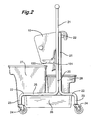
- the mopping trolley in accordance with the present invention comprises a generally tubular frame 20 having a central upstanding portion 21 and a horizontal portions 22 which serve to form a base frame together with corresponding portions on the far side (not visible).
- the frame 20 has, towards each corner (near two visible), a downwardly projecting portion 23 which carries at its lower end a caster indicated generally at 24.
- a base frame member 25 of the trolley carries a plastic tray 26 adapted to accommodate a pair of buckets 27 and 28 respectively.
- the buckets are disposed fore-aft, so that bucket 27 is at a front end region of the trolley (i.e. working side), whereas the bucket 28 is at a rear end region of the trolley.
- the bucket 27 has approximately twice the capacity of bucket 28 and is adapted to be filled with cleaning fluid for application to the floor by dipping a mop head into the fluid in bucket 27, shaking the surplus from the mop head back into the bucket and then applying the cleaning fluid to a floor to be cleaned in even strokes to distribute cleaning fluid thereover.
- the mop head (not shown in figure 2 , but as shown in figure 1 ) may be returned to a mop press 10.
- the mop press is hung from a transverse space frame member 22.
- the mop press is then used to express dirty fluid from the mop head in the usual manner.
- the mop press has the general configuration of that shown in figure 1 . However, the mop press is provided with an end cap 100 formed of moulded plastics material.
- the end cap is formed with a diverting discharge port 101 at a lower rear end region thereof. This drains over and directly into the rear bucket 27, as shown in figure 2 . In this way, waste water drains directly into the rear waste bucket, even though the mop press sits generally above and over the front clean bucket. The pressed mop may then be entered into the clean bucket for charging with cleaning fluid, and the cleaning process repeated.
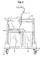
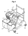
- FIG. 3 and 4 provides for a larger receptacle 37 and a smaller receptacle 38 to be accommodated in side-by-side relationship. Common features are numbered as per figures 1 and 2 .
- the physical height of each receptacle is the same but the volumetric capacity of the receptacle 37 is approximately twice that of the "waste" receptacle or bucket 38.
- the upper part of bucket 38 is provided with a lateral projection 40 towards the rear of bucket 38 and on one side thereof, the projection 40 being of a sufficient depth that water can be discharged into it without significant splashing.
- the base of the projection is closed to guide the water entering projection 40 (dashed lines in figure 3 ) into the main body of volume of receptacle 38.
- the larger container 37 which contains clean water and cleaning agent solution, is correspondingly shaped at 41 (see figure 4 ) to accommodated the projection 40 from the adjacent bucket, so that the two buckets nest together.
- the wall of the bucket 37 is shaped over its whole depth to accommodate the projection 40 of bucket 38. In this way, the "clean" bucket 37 can be removed from tray 25 without disturbing bucket 38.
- a portion of the body of bucket 37 may be expanded to extend under the overlay portion 40 of bucket 38 thereby increasing the volume of the "clean" bucket 37 still further.
- the mop press has an alternatively configured end cap 100.
- the end cap has a bottom side that is inclined down towards the waste bucket 38.
- a diverting discharge, port 101 is formed at the side region of the end cap, so that the port drains onto the projection 40 of the waste bucket.
- the mop press drains directly into the waste bucket 38, whilst being located above the clean water bucket 37.
- a mop head (not shown) may be taken from the mop press and allowed to drop back into the cleaning fluid bucket 37 without moving the mop head laterally from the waste bucket (as would be the case for a prior art arrangement in which the mop head was pressed over the waste bucket., as shown in figure 1B ). This makes the mopping pressing and charging actions considerably more convenient for the operator.
- the relatively shallow depth of the overlay portion 40 means that the bucket 38 can be removed easily, with bucket 37 remaining in place without requiring an operative to life a heavy bucket full of water to a considerable height.
- the relatively large size of the cleaning bucket ensures that few trips to water replenishment stations are necessary, thereby increasing the operative's effective cleaning time.
- the combination of bucket size differential, location of the mop press over the cleaning bucket and draining port orientation over the waste bucket provides enhanced mopping efficiency.
Landscapes
- Cleaning Implements For Floors, Carpets, Furniture, Walls, And The Like (AREA)
- Inorganic Fibers (AREA)
- Current-Collector Devices For Electrically Propelled Vehicles (AREA)
- Length Measuring Devices By Optical Means (AREA)
- Pinball Game Machines (AREA)
- Magnetic Resonance Imaging Apparatus (AREA)
- Vehicle Cleaning, Maintenance, Repair, Refitting, And Outriggers (AREA)
Claims (10)
- Chariot de nettoyage comprenant des moyens formant chariot (20 à 25) capables d'effectuer un mouvement de translation sur une surface, un ensemble de presse de balai à franges (10) supporté par lesdits moyens formant chariot pour exprimer un liquide d'une tête de balai à franges insérée dans la presse et au moins deux réceptacles de liquide, dans lequel un réceptacle de vidange (28, 38) est agencé pour recevoir le liquide usagé exprimé de la tête de balai à franges, et un réceptacle propre (27, 37) sert à fournir une source de liquide propre destiné à être utilisé pour nettoyer, caractérisé en ce que la presse de balai à franges (10) se trouve généralement au-dessus du réceptacle propre (27, 37) et le réceptacle de vidange (28, 38) est en communication fluidique avec un orifice de décharge de dérivation (101) de la presse de balai à franges (10), moyennant quoi le liquide exprimé de la tête de balai à franges est transporté vers le réceptacle de vidange (28, 38).
- Chariot de nettoyage selon la revendication 1, dans lequel le réceptacle propre (27, 37) a une capacité volumétrique supérieure à celle du réceptacle de vidange (28, 38).
- Chariot de nettoyage selon la revendication 2, dans lequel le réceptacle propre (27, 37) a une capacité qui est supérieure d'au moins 40 % celle du réceptacle de vidange (28, 38) ; optionnellement dans lequel le réceptacle propre (27, 37) a une capacité qui est supérieure d'au moins 50 % à celle du réceptacle de vidange (28, 38).
- Chariot de nettoyage selon l'une quelconque des revendications précédentes, dans lequel les réceptacles de vidange (28, 38) et propre (27, 37) sont situés sur le chariot en un agencement côte à côte de sorte que les réceptacles occupent une région avant du chariot.
- Chariot de nettoyage selon la revendication 4, dans lequel le réceptacle de vidange (28, 38) comporte une protubérance de bord (40) qui s'étend au-dessous de l'orifice de décharge de dérivation de presse de balai à franges (101), pour recueillir de ce fait le fluide exprimé de la tête de balai à franges par la presse de balai à franges (10) ; optionnellement dans lequel la protubérance de bord (40) du réceptacle de vidange (28, 38) s'emboîte dans un évidement (41) correspondant dans le réceptacle propre (27, 37) de sorte que les réceptacles puissent être placés à proximité étroite l'un de l'autre.
- Chariot de nettoyage selon l'une quelconque des revendications précédentes, dans lequel l'orifice de décharge de dérivation (101) de la presse de nettoyage (10) est prévu d'un côté d'une région inférieure de la presse de balai à franges (10), de sorte que le liquide soit déchargé à partir d'un côté de la presse de balai à franges (10).
- Chariot de nettoyage selon l'une quelconque des revendications 1 à 3, dans lequel les réceptacles de vidange (28, 38) et propre (27, 37) sont situés sur le chariot en un agencement avant et arrière de sorte que le réceptacle propre (27, 37) occupe une région avant du chariot, et le réceptacle de vidange (28, 38) occupe une région arrière du chariot.
- Chariot de nettoyage selon la revendication 7, dans lequel la presse de balai à franges (10) est pourvue de l'orifice de décharge de dérivation (101) qui dirige le liquide exprimé d'une tête de balai à franges généralement vers l'arrière dans le réceptacle de vidange (28, 38) ; optionnellement dans lequel l'orifice de décharge de dérivation (101) comprend un orifice formé à une extrémité arrière d'une région inférieure de la presse de balai à franges (10).
- Presse de nettoyage selon l'une quelconque des revendications précédentes, dans laquelle l'orifice de décharge de dérivation (101) pour la presse de nettoyage (10) est formé dans un couvercle d'extrémité (100) fixé à une région d'extrémité inférieure de la presse de balai à franges (10).
- Presse de nettoyage selon l'une quelconque des revendications précédentes, dans laquelle les réceptacles sont situés de manière amovible sur le chariot et chaque réceptacle peut être retiré indépendamment de l'autre, par exemple pour la décharge du liquide usagé ou le réapprovisionnement en liquide propre.
Applications Claiming Priority (3)
| Application Number | Priority Date | Filing Date | Title |
|---|---|---|---|
| GB0208274 | 2002-04-10 | ||
| GBGB0208274.1A GB0208274D0 (en) | 2002-04-10 | 2002-04-10 | Mopping trolleys |
| PCT/GB2003/001527 WO2003086166A1 (fr) | 2002-04-10 | 2003-04-09 | Chariots a essoreuse |
Publications (2)
| Publication Number | Publication Date |
|---|---|
| EP1494571A1 EP1494571A1 (fr) | 2005-01-12 |
| EP1494571B1 true EP1494571B1 (fr) | 2009-01-28 |
Family
ID=9934605
Family Applications (1)
| Application Number | Title | Priority Date | Filing Date |
|---|---|---|---|
| EP03715133A Expired - Lifetime EP1494571B1 (fr) | 2002-04-10 | 2003-04-09 | Chariots a essoreuse |
Country Status (8)
| Country | Link |
|---|---|
| US (1) | US7587784B2 (fr) |
| EP (1) | EP1494571B1 (fr) |
| AT (1) | ATE421862T1 (fr) |
| AU (1) | AU2003219324A1 (fr) |
| DE (1) | DE60326034D1 (fr) |
| GB (1) | GB0208274D0 (fr) |
| WO (1) | WO2003086166A1 (fr) |
| ZA (1) | ZA200408024B (fr) |
Families Citing this family (18)
| Publication number | Priority date | Publication date | Assignee | Title |
|---|---|---|---|---|
| GB0208274D0 (en) * | 2002-04-10 | 2002-05-22 | Numatic Int Ltd | Mopping trolleys |
| DE102005013949A1 (de) * | 2005-03-26 | 2006-09-28 | Carl Zeiss Meditec Ag | Scanvorrichtung |
| IL174590A (en) * | 2005-03-29 | 2015-03-31 | Yoel Arieli | A method and an imaging system for the analysis of optical properties of an object illuminated by a light source |
| CN100459924C (zh) * | 2007-02-27 | 2009-02-11 | 孟少甫 | 多功能墩布清洗脱水机 |
| US8381931B1 (en) * | 2007-06-05 | 2013-02-26 | Roger Ernest, III | Integrated dual container bucket assembly |
| US9980623B2 (en) | 2008-11-05 | 2018-05-29 | Ecolab Usa Inc. | Cleaning trolley |
| US8381351B2 (en) * | 2009-01-08 | 2013-02-26 | Shop-Vac | Mop bucket |
| US8544141B1 (en) * | 2009-03-04 | 2013-10-01 | Kaivac, Inc. | Cleaning cart systems |
| USD624270S1 (en) | 2009-11-03 | 2010-09-21 | Ecolab Inc. | Cleaning trolley |
| USD624271S1 (en) | 2009-11-03 | 2010-09-21 | Ecolab Inc. | Cleaning trolley |
| USD624269S1 (en) | 2009-11-03 | 2010-09-21 | Ecolab Inc. | Cleaning trolley |
| USD624724S1 (en) | 2009-11-03 | 2010-09-28 | Ecolab Inc. | Cleaning trolley |
| IT1397759B1 (it) * | 2010-01-22 | 2013-01-24 | T T S S R L Tecno Trolley System | Secchio per pulizie impilabile. |
| USD643982S1 (en) | 2011-01-12 | 2011-08-23 | The Libman Company | Wringer |
| DE102013011632A1 (de) * | 2013-07-12 | 2015-01-15 | Carl Freudenberg Kg | Reinigungswagen |
| GB2518450B (en) * | 2013-09-24 | 2016-01-27 | Numatic Int Ltd | Mopping stand or trolley |
| RU2017105412A (ru) * | 2014-08-26 | 2018-09-27 | Авент, Инк. | Способ и система для нахождения источника хронической боли и ее устранения |
| US20180296060A1 (en) * | 2015-10-05 | 2018-10-18 | Lou Lentine | Mop Bucket |
Family Cites Families (11)
| Publication number | Priority date | Publication date | Assignee | Title |
|---|---|---|---|---|
| US1767840A (en) * | 1927-08-08 | 1930-06-24 | Walter S Finnell | Receptacle for mopping machines |
| US2397707A (en) * | 1943-12-08 | 1946-04-02 | Harold A Travis | Floor cleaning apparatus |
| US3504392A (en) * | 1967-11-15 | 1970-04-07 | Det Danske Rengorings Selskab | Transport carriage for a cleaning device |
| DE4320454A1 (de) | 1993-06-21 | 1994-12-22 | Henkel Ecolab Gmbh & Co Ohg | Fahrbarer Reinigungswagen |
| ITPD930187A1 (it) | 1993-09-24 | 1995-03-24 | T T S Societa Responsabilita L | Carrello a struttura articolata con possibilita' di ridurne l'ingombro durante il non uso, adatto al trasporto ed al montaggio di |
| US5440778A (en) * | 1994-09-30 | 1995-08-15 | Micronova Manufacturing, Inc. | Multiple purpose wringer |
| LU88745A1 (fr) | 1996-04-18 | 1996-10-04 | Az Int Sa | Chariot de nettoyage utilisable plus particulièrement pour le transport de seaux et le soutien d'une essoreuse réalisé en totalité en une matière résineuse d'une seule pièce |
| LU90140B1 (fr) * | 1997-09-26 | 1998-01-29 | Az Int Sa | Cuvette d'essorage d'une serpillière montée en position centrale sur un seau à deux bassins |
| WO2000069321A1 (fr) * | 1999-05-14 | 2000-11-23 | Numatic International Limited | Essoreur pour lave-sol |
| SE520192C2 (sv) * | 2001-08-17 | 2003-06-10 | Monitor Film & Television Ab | Anordning, metod och användning av en anordning vid en städvagn för sköljning, rengöring och urvridning av en skurmopp |
| GB0208274D0 (en) * | 2002-04-10 | 2002-05-22 | Numatic Int Ltd | Mopping trolleys |
-
2002
- 2002-04-10 GB GBGB0208274.1A patent/GB0208274D0/en not_active Ceased
-
2003
- 2003-04-09 AU AU2003219324A patent/AU2003219324A1/en not_active Abandoned
- 2003-04-09 US US10/510,462 patent/US7587784B2/en not_active Expired - Lifetime
- 2003-04-09 DE DE60326034T patent/DE60326034D1/de not_active Expired - Lifetime
- 2003-04-09 WO PCT/GB2003/001527 patent/WO2003086166A1/fr not_active Ceased
- 2003-04-09 EP EP03715133A patent/EP1494571B1/fr not_active Expired - Lifetime
- 2003-04-09 AT AT03715133T patent/ATE421862T1/de not_active IP Right Cessation
-
2004
- 2004-10-05 ZA ZA200408024A patent/ZA200408024B/en unknown
Also Published As
| Publication number | Publication date |
|---|---|
| GB0208274D0 (en) | 2002-05-22 |
| WO2003086166A1 (fr) | 2003-10-23 |
| ZA200408024B (en) | 2005-10-05 |
| DE60326034D1 (de) | 2009-03-19 |
| ATE421862T1 (de) | 2009-02-15 |
| US20060010637A1 (en) | 2006-01-19 |
| EP1494571A1 (fr) | 2005-01-12 |
| AU2003219324A1 (en) | 2003-10-27 |
| US7587784B2 (en) | 2009-09-15 |
Similar Documents
| Publication | Publication Date | Title |
|---|---|---|
| EP1494571B1 (fr) | Chariots a essoreuse | |
| US5548865A (en) | Floor cloth bucket and wringer device | |
| US5983441A (en) | Bucket insert and wash bucket | |
| US6457203B1 (en) | Bucket insert and wash bucket | |
| US11805959B2 (en) | Mop bucket | |
| US5414892A (en) | Mop bucket cover having wringer and storage device | |
| DK154866B (da) | Maskine til rengoering af fortrinsvis haarde underlag | |
| US4888847A (en) | Scrubbing pail device | |
| US4297762A (en) | Paint tray and reservoir | |
| EP1516575B1 (fr) | Chariot pour une essoreuse | |
| GB2260691A (en) | Liquid container provided with a filter | |
| CN205672005U (zh) | 拖把清洁桶装置 | |
| US7003843B1 (en) | Garbage can cleaning system | |
| EP2449941B1 (fr) | Ensemble essoreuse et seau de serpillière | |
| US20070022559A1 (en) | Mop bucket bag insert | |
| WO1999000050A1 (fr) | Balai laveur | |
| CN213030570U (zh) | 一种带座马桶刷 | |
| EP4388965A1 (fr) | Seau de lavage de balai à franges à compartiments multiples | |
| GB2283438A (en) | Improvements in and relating to vacuum cleaning apparatus | |
| US2337179A (en) | Dispensing mechanism | |
| CN212591978U (zh) | 一种清洁工具放置箱 | |
| CN216786571U (zh) | 储液盒及投放组件、洗涤设备 | |
| CN211990008U (zh) | 适用于水式板擦的清洗箱 | |
| WO1999051137A1 (fr) | Presse et support de presse de balai a laver | |
| JPS6132508Y2 (fr) |
Legal Events
| Date | Code | Title | Description |
|---|---|---|---|
| PUAI | Public reference made under article 153(3) epc to a published international application that has entered the european phase |
Free format text: ORIGINAL CODE: 0009012 |
|
| 17P | Request for examination filed |
Effective date: 20040930 |
|
| AK | Designated contracting states |
Kind code of ref document: A1 Designated state(s): AT BE BG CH CY CZ DE DK EE ES FI FR GB GR HU IE IT LI LU MC NL PT RO SE SI SK TR |
|
| AX | Request for extension of the european patent |
Extension state: AL LT LV MK |
|
| GRAP | Despatch of communication of intention to grant a patent |
Free format text: ORIGINAL CODE: EPIDOSNIGR1 |
|
| GRAS | Grant fee paid |
Free format text: ORIGINAL CODE: EPIDOSNIGR3 |
|
| GRAA | (expected) grant |
Free format text: ORIGINAL CODE: 0009210 |
|
| AK | Designated contracting states |
Kind code of ref document: B1 Designated state(s): AT BE BG CH CY CZ DE DK EE ES FI FR GB GR HU IE IT LI LU MC NL PT RO SE SI SK TR |
|
| REG | Reference to a national code |
Ref country code: GB Ref legal event code: FG4D |
|
| REG | Reference to a national code |
Ref country code: CH Ref legal event code: EP |
|
| REG | Reference to a national code |
Ref country code: IE Ref legal event code: FG4D |
|
| REF | Corresponds to: |
Ref document number: 60326034 Country of ref document: DE Date of ref document: 20090319 Kind code of ref document: P |
|
| PG25 | Lapsed in a contracting state [announced via postgrant information from national office to epo] |
Ref country code: SI Free format text: LAPSE BECAUSE OF FAILURE TO SUBMIT A TRANSLATION OF THE DESCRIPTION OR TO PAY THE FEE WITHIN THE PRESCRIBED TIME-LIMIT Effective date: 20090128 Ref country code: ES Free format text: LAPSE BECAUSE OF FAILURE TO SUBMIT A TRANSLATION OF THE DESCRIPTION OR TO PAY THE FEE WITHIN THE PRESCRIBED TIME-LIMIT Effective date: 20090509 Ref country code: FI Free format text: LAPSE BECAUSE OF FAILURE TO SUBMIT A TRANSLATION OF THE DESCRIPTION OR TO PAY THE FEE WITHIN THE PRESCRIBED TIME-LIMIT Effective date: 20090128 |
|
| PG25 | Lapsed in a contracting state [announced via postgrant information from national office to epo] |
Ref country code: AT Free format text: LAPSE BECAUSE OF FAILURE TO SUBMIT A TRANSLATION OF THE DESCRIPTION OR TO PAY THE FEE WITHIN THE PRESCRIBED TIME-LIMIT Effective date: 20090128 Ref country code: PT Free format text: LAPSE BECAUSE OF FAILURE TO SUBMIT A TRANSLATION OF THE DESCRIPTION OR TO PAY THE FEE WITHIN THE PRESCRIBED TIME-LIMIT Effective date: 20090629 Ref country code: SE Free format text: LAPSE BECAUSE OF FAILURE TO SUBMIT A TRANSLATION OF THE DESCRIPTION OR TO PAY THE FEE WITHIN THE PRESCRIBED TIME-LIMIT Effective date: 20090428 |
|
| PG25 | Lapsed in a contracting state [announced via postgrant information from national office to epo] |
Ref country code: BE Free format text: LAPSE BECAUSE OF FAILURE TO SUBMIT A TRANSLATION OF THE DESCRIPTION OR TO PAY THE FEE WITHIN THE PRESCRIBED TIME-LIMIT Effective date: 20090128 |
|
| PG25 | Lapsed in a contracting state [announced via postgrant information from national office to epo] |
Ref country code: EE Free format text: LAPSE BECAUSE OF FAILURE TO SUBMIT A TRANSLATION OF THE DESCRIPTION OR TO PAY THE FEE WITHIN THE PRESCRIBED TIME-LIMIT Effective date: 20090128 Ref country code: DK Free format text: LAPSE BECAUSE OF FAILURE TO SUBMIT A TRANSLATION OF THE DESCRIPTION OR TO PAY THE FEE WITHIN THE PRESCRIBED TIME-LIMIT Effective date: 20090128 Ref country code: CZ Free format text: LAPSE BECAUSE OF FAILURE TO SUBMIT A TRANSLATION OF THE DESCRIPTION OR TO PAY THE FEE WITHIN THE PRESCRIBED TIME-LIMIT Effective date: 20090128 |
|
| PG25 | Lapsed in a contracting state [announced via postgrant information from national office to epo] |
Ref country code: RO Free format text: LAPSE BECAUSE OF FAILURE TO SUBMIT A TRANSLATION OF THE DESCRIPTION OR TO PAY THE FEE WITHIN THE PRESCRIBED TIME-LIMIT Effective date: 20090128 Ref country code: SK Free format text: LAPSE BECAUSE OF FAILURE TO SUBMIT A TRANSLATION OF THE DESCRIPTION OR TO PAY THE FEE WITHIN THE PRESCRIBED TIME-LIMIT Effective date: 20090128 |
|
| REG | Reference to a national code |
Ref country code: CH Ref legal event code: PL |
|
| PLBE | No opposition filed within time limit |
Free format text: ORIGINAL CODE: 0009261 |
|
| STAA | Information on the status of an ep patent application or granted ep patent |
Free format text: STATUS: NO OPPOSITION FILED WITHIN TIME LIMIT |
|
| 26N | No opposition filed |
Effective date: 20091029 |
|
| PG25 | Lapsed in a contracting state [announced via postgrant information from national office to epo] |
Ref country code: LI Free format text: LAPSE BECAUSE OF NON-PAYMENT OF DUE FEES Effective date: 20090430 Ref country code: BG Free format text: LAPSE BECAUSE OF FAILURE TO SUBMIT A TRANSLATION OF THE DESCRIPTION OR TO PAY THE FEE WITHIN THE PRESCRIBED TIME-LIMIT Effective date: 20090428 Ref country code: CH Free format text: LAPSE BECAUSE OF NON-PAYMENT OF DUE FEES Effective date: 20090430 |
|
| REG | Reference to a national code |
Ref country code: IE Ref legal event code: MM4A |
|
| PG25 | Lapsed in a contracting state [announced via postgrant information from national office to epo] |
Ref country code: IE Free format text: LAPSE BECAUSE OF NON-PAYMENT OF DUE FEES Effective date: 20090409 Ref country code: MC Free format text: LAPSE BECAUSE OF NON-PAYMENT OF DUE FEES Effective date: 20090430 |
|
| PG25 | Lapsed in a contracting state [announced via postgrant information from national office to epo] |
Ref country code: GR Free format text: LAPSE BECAUSE OF FAILURE TO SUBMIT A TRANSLATION OF THE DESCRIPTION OR TO PAY THE FEE WITHIN THE PRESCRIBED TIME-LIMIT Effective date: 20090429 |
|
| PG25 | Lapsed in a contracting state [announced via postgrant information from national office to epo] |
Ref country code: IT Free format text: LAPSE BECAUSE OF FAILURE TO SUBMIT A TRANSLATION OF THE DESCRIPTION OR TO PAY THE FEE WITHIN THE PRESCRIBED TIME-LIMIT Effective date: 20090128 |
|
| PG25 | Lapsed in a contracting state [announced via postgrant information from national office to epo] |
Ref country code: LU Free format text: LAPSE BECAUSE OF NON-PAYMENT OF DUE FEES Effective date: 20090409 |
|
| PG25 | Lapsed in a contracting state [announced via postgrant information from national office to epo] |
Ref country code: HU Free format text: LAPSE BECAUSE OF FAILURE TO SUBMIT A TRANSLATION OF THE DESCRIPTION OR TO PAY THE FEE WITHIN THE PRESCRIBED TIME-LIMIT Effective date: 20090729 |
|
| PGFP | Annual fee paid to national office [announced via postgrant information from national office to epo] |
Ref country code: FR Payment date: 20110510 Year of fee payment: 9 |
|
| PG25 | Lapsed in a contracting state [announced via postgrant information from national office to epo] |
Ref country code: TR Free format text: LAPSE BECAUSE OF FAILURE TO SUBMIT A TRANSLATION OF THE DESCRIPTION OR TO PAY THE FEE WITHIN THE PRESCRIBED TIME-LIMIT Effective date: 20090128 |
|
| PGFP | Annual fee paid to national office [announced via postgrant information from national office to epo] |
Ref country code: GB Payment date: 20110426 Year of fee payment: 9 Ref country code: NL Payment date: 20110503 Year of fee payment: 9 |
|
| PG25 | Lapsed in a contracting state [announced via postgrant information from national office to epo] |
Ref country code: CY Free format text: LAPSE BECAUSE OF FAILURE TO SUBMIT A TRANSLATION OF THE DESCRIPTION OR TO PAY THE FEE WITHIN THE PRESCRIBED TIME-LIMIT Effective date: 20090128 |
|
| PGFP | Annual fee paid to national office [announced via postgrant information from national office to epo] |
Ref country code: DE Payment date: 20110628 Year of fee payment: 9 |
|
| REG | Reference to a national code |
Ref country code: NL Ref legal event code: V1 Effective date: 20121101 |
|
| GBPC | Gb: european patent ceased through non-payment of renewal fee |
Effective date: 20120409 |
|
| REG | Reference to a national code |
Ref country code: FR Ref legal event code: ST Effective date: 20121228 |
|
| PG25 | Lapsed in a contracting state [announced via postgrant information from national office to epo] |
Ref country code: GB Free format text: LAPSE BECAUSE OF NON-PAYMENT OF DUE FEES Effective date: 20120409 |
|
| REG | Reference to a national code |
Ref country code: DE Ref legal event code: R119 Ref document number: 60326034 Country of ref document: DE Effective date: 20121101 |
|
| PG25 | Lapsed in a contracting state [announced via postgrant information from national office to epo] |
Ref country code: FR Free format text: LAPSE BECAUSE OF NON-PAYMENT OF DUE FEES Effective date: 20120430 |
|
| PG25 | Lapsed in a contracting state [announced via postgrant information from national office to epo] |
Ref country code: NL Free format text: LAPSE BECAUSE OF NON-PAYMENT OF DUE FEES Effective date: 20121101 |
|
| PG25 | Lapsed in a contracting state [announced via postgrant information from national office to epo] |
Ref country code: DE Free format text: LAPSE BECAUSE OF NON-PAYMENT OF DUE FEES Effective date: 20121101 |