EP1494627B1 - Schiene für eine gelenkverbindung und verfahren zur herstellung einer solchen schiene - Google Patents
Schiene für eine gelenkverbindung und verfahren zur herstellung einer solchen schiene Download PDFInfo
- Publication number
- EP1494627B1 EP1494627B1 EP03746347A EP03746347A EP1494627B1 EP 1494627 B1 EP1494627 B1 EP 1494627B1 EP 03746347 A EP03746347 A EP 03746347A EP 03746347 A EP03746347 A EP 03746347A EP 1494627 B1 EP1494627 B1 EP 1494627B1
- Authority
- EP
- European Patent Office
- Prior art keywords
- shell
- splint
- ankle
- joint
- face
- Prior art date
- Legal status (The legal status is an assumption and is not a legal conclusion. Google has not performed a legal analysis and makes no representation as to the accuracy of the status listed.)
- Expired - Lifetime
Links
- 238000004519 manufacturing process Methods 0.000 title claims description 3
- 238000000034 method Methods 0.000 title description 3
- 208000027418 Wounds and injury Diseases 0.000 claims abstract description 6
- 230000006378 damage Effects 0.000 claims abstract description 6
- 208000014674 injury Diseases 0.000 claims abstract description 6
- 210000003423 ankle Anatomy 0.000 claims description 51
- 239000004744 fabric Substances 0.000 claims description 18
- 239000000463 material Substances 0.000 claims description 16
- 206010024453 Ligament sprain Diseases 0.000 claims description 14
- 208000010040 Sprains and Strains Diseases 0.000 claims description 13
- 210000002683 foot Anatomy 0.000 claims description 11
- 210000003127 knee Anatomy 0.000 claims description 6
- 241001465754 Metazoa Species 0.000 claims description 5
- 229920002292 Nylon 6 Polymers 0.000 claims description 5
- 229920002457 flexible plastic Polymers 0.000 claims description 5
- 239000006260 foam Substances 0.000 claims description 5
- 229920002994 synthetic fiber Polymers 0.000 claims description 5
- -1 styrene-ethylene-butylene-styrene Chemical class 0.000 claims description 4
- 239000007788 liquid Substances 0.000 claims description 3
- 229920001577 copolymer Polymers 0.000 claims 3
- QQONPFPTGQHPMA-UHFFFAOYSA-N propylene Natural products CC=C QQONPFPTGQHPMA-UHFFFAOYSA-N 0.000 claims 3
- 229920001400 block copolymer Polymers 0.000 claims 2
- 210000004872 soft tissue Anatomy 0.000 abstract 1
- 235000005921 Cynara humilis Nutrition 0.000 description 6
- 240000002228 Cynara humilis Species 0.000 description 6
- 230000002497 edematous effect Effects 0.000 description 6
- 210000002414 leg Anatomy 0.000 description 6
- 206010030113 Oedema Diseases 0.000 description 4
- 210000001513 elbow Anatomy 0.000 description 4
- 239000004677 Nylon Substances 0.000 description 3
- 229920001778 nylon Polymers 0.000 description 3
- 229920005606 polypropylene copolymer Polymers 0.000 description 3
- 230000000284 resting effect Effects 0.000 description 3
- 238000001816 cooling Methods 0.000 description 2
- 230000000694 effects Effects 0.000 description 2
- 229920001971 elastomer Polymers 0.000 description 2
- BYSRUWKGUGERFI-UHFFFAOYSA-N hex-1-en-3-yne Chemical group CCC#CC=C BYSRUWKGUGERFI-UHFFFAOYSA-N 0.000 description 2
- 229920001903 high density polyethylene Polymers 0.000 description 2
- 239000004700 high-density polyethylene Substances 0.000 description 2
- 239000005060 rubber Substances 0.000 description 2
- 229920006132 styrene block copolymer Polymers 0.000 description 2
- 239000004721 Polyphenylene oxide Substances 0.000 description 1
- 238000010521 absorption reaction Methods 0.000 description 1
- 238000007664 blowing Methods 0.000 description 1
- 230000006835 compression Effects 0.000 description 1
- 238000007906 compression Methods 0.000 description 1
- 230000008878 coupling Effects 0.000 description 1
- 238000010168 coupling process Methods 0.000 description 1
- 238000005859 coupling reaction Methods 0.000 description 1
- 230000008034 disappearance Effects 0.000 description 1
- 239000011521 glass Substances 0.000 description 1
- 239000003292 glue Substances 0.000 description 1
- 238000000465 moulding Methods 0.000 description 1
- 229920000570 polyether Polymers 0.000 description 1
- 229920002635 polyurethane Polymers 0.000 description 1
- 239000004814 polyurethane Substances 0.000 description 1
- 230000002035 prolonged effect Effects 0.000 description 1
- 230000001737 promoting effect Effects 0.000 description 1
- 239000012858 resilient material Substances 0.000 description 1
- 238000007789 sealing Methods 0.000 description 1
- 210000002435 tendon Anatomy 0.000 description 1
- 229920002725 thermoplastic elastomer Polymers 0.000 description 1
- 210000000707 wrist Anatomy 0.000 description 1
Images



Classifications
-
- B—PERFORMING OPERATIONS; TRANSPORTING
- B29—WORKING OF PLASTICS; WORKING OF SUBSTANCES IN A PLASTIC STATE IN GENERAL
- B29C—SHAPING OR JOINING OF PLASTICS; SHAPING OF MATERIAL IN A PLASTIC STATE, NOT OTHERWISE PROVIDED FOR; AFTER-TREATMENT OF THE SHAPED PRODUCTS, e.g. REPAIRING
- B29C39/00—Shaping by casting, i.e. introducing the moulding material into a mould or between confining surfaces without significant moulding pressure; Apparatus therefor
- B29C39/02—Shaping by casting, i.e. introducing the moulding material into a mould or between confining surfaces without significant moulding pressure; Apparatus therefor for making articles of definite length, i.e. discrete articles
- B29C39/021—Shaping by casting, i.e. introducing the moulding material into a mould or between confining surfaces without significant moulding pressure; Apparatus therefor for making articles of definite length, i.e. discrete articles by casting in several steps
- B29C39/025—Shaping by casting, i.e. introducing the moulding material into a mould or between confining surfaces without significant moulding pressure; Apparatus therefor for making articles of definite length, i.e. discrete articles by casting in several steps for making multilayered articles
-
- A—HUMAN NECESSITIES
- A61—MEDICAL OR VETERINARY SCIENCE; HYGIENE
- A61F—FILTERS IMPLANTABLE INTO BLOOD VESSELS; PROSTHESES; DEVICES PROVIDING PATENCY TO, OR PREVENTING COLLAPSING OF, TUBULAR STRUCTURES OF THE BODY, e.g. STENTS; ORTHOPAEDIC, NURSING OR CONTRACEPTIVE DEVICES; FOMENTATION; TREATMENT OR PROTECTION OF EYES OR EARS; BANDAGES, DRESSINGS OR ABSORBENT PADS; FIRST-AID KITS
- A61F5/00—Orthopaedic methods or devices for non-surgical treatment of bones or joints; Nursing devices ; Anti-rape devices
- A61F5/01—Orthopaedic devices, e.g. long-term immobilising or pressure directing devices for treating broken or deformed bones such as splints, casts or braces
- A61F5/0102—Orthopaedic devices, e.g. long-term immobilising or pressure directing devices for treating broken or deformed bones such as splints, casts or braces specially adapted for correcting deformities of the limbs or for supporting them; Ortheses, e.g. with articulations
- A61F5/0104—Orthopaedic devices, e.g. long-term immobilising or pressure directing devices for treating broken or deformed bones such as splints, casts or braces specially adapted for correcting deformities of the limbs or for supporting them; Ortheses, e.g. with articulations without articulation
- A61F5/0111—Orthopaedic devices, e.g. long-term immobilising or pressure directing devices for treating broken or deformed bones such as splints, casts or braces specially adapted for correcting deformities of the limbs or for supporting them; Ortheses, e.g. with articulations without articulation for the feet or ankles
-
- A—HUMAN NECESSITIES
- A61—MEDICAL OR VETERINARY SCIENCE; HYGIENE
- A61F—FILTERS IMPLANTABLE INTO BLOOD VESSELS; PROSTHESES; DEVICES PROVIDING PATENCY TO, OR PREVENTING COLLAPSING OF, TUBULAR STRUCTURES OF THE BODY, e.g. STENTS; ORTHOPAEDIC, NURSING OR CONTRACEPTIVE DEVICES; FOMENTATION; TREATMENT OR PROTECTION OF EYES OR EARS; BANDAGES, DRESSINGS OR ABSORBENT PADS; FIRST-AID KITS
- A61F5/00—Orthopaedic methods or devices for non-surgical treatment of bones or joints; Nursing devices ; Anti-rape devices
- A61F5/01—Orthopaedic devices, e.g. long-term immobilising or pressure directing devices for treating broken or deformed bones such as splints, casts or braces
- A61F5/0102—Orthopaedic devices, e.g. long-term immobilising or pressure directing devices for treating broken or deformed bones such as splints, casts or braces specially adapted for correcting deformities of the limbs or for supporting them; Ortheses, e.g. with articulations
- A61F5/012—Orthopaedic devices, e.g. long-term immobilising or pressure directing devices for treating broken or deformed bones such as splints, casts or braces specially adapted for correcting deformities of the limbs or for supporting them; Ortheses, e.g. with articulations inflatable
-
- B—PERFORMING OPERATIONS; TRANSPORTING
- B29—WORKING OF PLASTICS; WORKING OF SUBSTANCES IN A PLASTIC STATE IN GENERAL
- B29K—INDEXING SCHEME ASSOCIATED WITH SUBCLASSES B29B, B29C OR B29D, RELATING TO MOULDING MATERIALS OR TO MATERIALS FOR MOULDS, REINFORCEMENTS, FILLERS OR PREFORMED PARTS, e.g. INSERTS
- B29K2995/00—Properties of moulding materials, reinforcements, fillers, preformed parts or moulds
- B29K2995/0037—Other properties
- B29K2995/0082—Flexural strength; Flexion stiffness
Definitions
- the present invention relates to a splint for a joint connecting two members of a human body or an animal, such as the ankle, knee or elbow for example, consisting of at least two rigid shells generally concave, capable of being positioned on either side of the articulation, resting on said articulation, comprising means making it possible to avoid any injury to the oedematous tissue which appears as a result of a sprain or a sprain of said articulation.
- splints to avoid eversion movements and inversion of the foot while allowing a normal flexion of the latter is to prevent a sprain or a sprained ankle, during the practice of a sport, for example, so as to promote the absorption of edema resulting from a sprain and located around the ankle.
- splints usually consist of two rigid globally concave shells, able to be positioned on either side of the ankle, resting on said peg, and respectively comprising on their internal faces, that is to say on their faces.
- concaves a chamber made of a flexible plastic material that can be pressurized by any appropriate means.
- the splint comprises means for maintaining said shells in position on either side of the hinge constituted by a web of tissue surrounding said hulls of the splint.
- Such a splint is described in the patent European EP 0 252 121 filed by the company AIRCAST concerning an ankle splint.
- This splint consists of an outer shell comprising two concave rigid shells able to be positioned on either side of the ankle and a base also rigid able to be positioned under the heel.
- the base comprises two tabs obtained in a strip of fabric extending on either side of said base and comprising on their outer faces, at their respective free ends, loops adapted to cooperate with hooks of the "velcro" type, which is a registered trademark, molded into the inner wall of each shell just above a generally rectangular horizontal lumen located at the lower end of each shell, each leg being threaded into the light of its respective shell from the outside towards inside the hull.
- the splint further includes first and second pressurizable chambers for providing a support pad between each shell and the ankle, the second chamber extending along the lower portion of the first chamber proximate to each other. from the base.
- the splint includes means for holding the shells in contact with the leg so that the pressure applied against the ankle by the second chamber is relatively greater than the pressure applied against the leg by the portion of the first chamber. extending above the second chamber.
- This type of splint has the disadvantage of having rigid edges that can bear on the edematous tissue of the ankle causing discomfort and pain caused by the pressure exerted by the rigid edges of the hulls. Furthermore, the legs of the splint base being secured to the inner walls of the hulls, it is necessary to completely remove the splint to be able to access said lugs and adjust appropriately the height of the hulls relative to the base, so that the splint is in most cases incorrectly positioned, which considerably of these splints.
- the pads of these splints have the disadvantage of peeling off, or even tearing in case of prolonged and repeated use of these splints, making them totally ineffective.
- the rubbing of the rubber on the skin of a patient wearing the bare foot brace is particularly unpleasant and may cause burns.
- One of the aims of the invention is therefore to overcome this disadvantage by proposing a splint for a joint connecting two members of a human body or an animal, such as ankle for example, of simple design and allowing avoid any injury to the edematous tissue that appears as a result of a sprain or strain of said joint.
- a splint for a joint connecting two members of a human body or an animal, such as the ankle, knee or elbow for example, consisting of less a rigid shell generally concave, consisting of a single element comprising at least one flexible zone, able to be positioned around the articulation, resting on said articulation, and comprising respectively on the inner face, that is to say say on the concave face, a chamber made of a flexible plastic material that can be pressurized by any suitable means, positioned on the inner face of the shell to provide a support cushion between said shell and the hinge, and covering at least a portion of the inner face of the shell, said splint comprising means for holding said hull in position around the hinge;
- SEBS styrene ethylene butylene styrene block copolymer
- the shell is rigid in its central part and flexible along its longitudinal edges.
- the edges of the hulls being flexible, the latter exert a reduced pressure on the edematous tissue resulting from a sprain or a sprain during flexion of the foot thus promoting a rapid resorption of edema.
- the SEBS which is a pleasant to the touch material improves the feeling of comfort for a user wearing the brace, the shell being obtained in a single part, that is to say from a single mold, the flexible zone of the shell does not tear unlike the devices of the prior art.
- Another object of the invention relates to a method of manufacturing the shell or shells of a splint for a joint connecting two members of a human body or the like, such as ankle, knee or elbow, for example, consisting of at least one rigid shell generally concave, adapted to be positioned around the joint, bearing on said articulation.
- This method consists in introducing a hot liquid synthetic material which is stiffened by cooling in a mold of shape corresponding to the shape of the shell to be obtained and then introducing into said mold a flexible material in at least one area of said mold.
- the flexible material is introduced into the synthetic material.
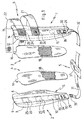
- the splint for ankle represented vertically on the figure 1 , consists of two rigid shells globally concave, a first so-called internal shell 1 adapted to be positioned on the inner side of the peg and a second so-called outer shell 2 adapted to be positioned on the outer side of said peg.
- Each inner and outer shell 1 and 2 comprises on their respective inner walls, that is to say their concave walls which are opposite the ankle when the splint is positioned around the latter, respectively a chamber 3 and 4 made a flexible plastic material that can be pressurized by any suitable means, such as a pipette for example, positioned on the inner wall of each shell 1 and 2 to provide a support cushion between each shell and the ankle.
- the splint further comprises a base 5 on which the heel of the foot is supported and means 6 for holding said shells 1 and 2 in position on either side of the ankle, the base 5 and the means 6 will be described more precisely a little further.
- the outer shell 2 comprises along its longitudinal edges respectively a flexible zone 7 and 8 in order to avoid any injury to the edematous tissue that appears as a result of sprain or strain of the ankle, the flexible zones 7 and 8 exerting a reduced pressure on the edematous tissue during flexion of the foot which promotes a rapid resorption of edema.
- the central portion 9 of the outer shell 2 extending from its lower end to its upper end is rigid; in this regard, the thickness of the outer shell in its central portion is preferably greater than the thickness of the flexible zones 7 and 8 of said outer shell 2.
- the outer shell 2 comprises in its central part a 10 generally circular flexible zone corresponding to a bearing zone of said outer shell on the external malleolus of the ankle which forms an outgrowth of this joint.
- the flexible zones 7, 8 or 10 consist of a zone of flexible material, SEBS, that is to say ethylene butylene styrene styrene block copolymer (thermoplastic elastomer), mixed with rigid synthetic material such as polypropylene copolymer (PPc) or polyamide 6 (PA 6), in which is obtained the rigid part of the outer shell 2.
- the flexible zones 7, 8 or 10 are obtained by introducing a synthetic material, such as PPc or PA6, for example, a hot liquid which is stiffened by cooling in a mold of shape corresponding to the shape of the shell in order to obtaining the rigid central portion 9, then introducing into said mold a flexible material, SEBS, in the mold area corresponding to the inside wall of the shell so that the flexible material extends on either side of the part rigid central 9 to form the flexible zones 7 and 8 and on the inner wall of said shell.
- SEBS which is a material particularly pleasant to the touch improves the feeling of comfort for a barefoot user for example.
- the outer shell 2 comprises along its front lateral edge, that is to say the vertical lateral edge located to the right of the figures 1 and 2 near its lower end, a notch 11 to avoid any pressure of the side edge against the kick hump during a flexion of the leg.
- the inner shell 1 comprises, in the same manner as above, along its longitudinal edges, respectively a flexible zone 12 and 13 delimited by dashed lines.
- the inner shell is rigid in its central portion 14 and has, in this regard, a thickness greater than the thickness of the flexible zones.
- the inner shell 1 comprises in its rigid central portion 14 a flexible zone 15 corresponding to the bearing zone of the inner shell 1 on the medial malleolus of the ankle.
- Rooms 3 and 4 with reference to figures 1 , 4 and 7 are secured to the inner walls of the inner and outer shells 1 and 2 respectively by any suitable means such as glue or Velcro-type fastening means (registered trademark) so that it covers the inner wall of each of the shells 1 and 2 to provide a support cushion between each shell 1 and 2 and the ankle.
- the chambers 3 and 4 have a generally triangular shape and comprise a valve 16 and 17 respectively adapted to cooperate with any appropriate means, such as a pipette consisting of a flexible tube, to pressurize said chambers 3 and 4, the setting under pressure being effected by blowing into the pipette introduced into the valve 16 or 17 of the chamber 3 or 4.
- each chamber 3 and 4 comprises a porous compressible element 18 positioned inside each of the chambers 3 and 4 substantially filling the interior volume of each of said chambers 3 and 4 when the latter are not pressurized.
- the porous compressible element 18 preferably consists of a slow-resilient foam such as the 1.50 LR3 low-resistance polyether foam marketed by TRAMICO, for example.
- slow-resilient foam is meant a foam which deforms under the effect of pressure and which returns very slowly to its initial position.
- chambers 3 and 4 are obtained by heat-sealing two generally triangular sheets 19 and 20 made of a flexible plastic material such as ethyl vinyl acetylene (EVA), and preferably polyurethane, thermally welded along their edges, porous compressible element 18 being positioned between the two sheets 19 and 20 before being heat-welded.
- EVA ethyl vinyl acetylene
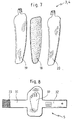
- the means 6 for holding in position the inner shell 1 and outer shell 2 on either side of the ankle consist of two strips of velvet fabric 21, 22, one free end of which is respectively secured to the outer wall of the inner shell 1 of the splint by a fastening means such as a rivet 23 for example.
- Each band 21,22 includes, with reference to figures 1 , 4 , 5 and 6 , male fastening means 24 secured to the outer face of the strips 21, 22 near the integral end of the inner shell, said male fastening means 24 being able to cooperate with the thin loops of the inner face of the strips of velvety fabric 21,22.
- Velvety fabric is understood to mean a fabric with two superimposed strings, one of which produces the bottom of the fabric and the other the velvet with fine loops on its sides. Moreover, the loops of the velvety fabric of the strips 21, 22 are able to cooperate with male fastening means 25 integral with the outer wall of the second outer shell 2.
- the male fastening means 25 secured to the outer wall of the outer shell 2 of the splint and able to cooperate with the thin loops of the strip 21,22 are respectively positioned in two recesses 26 formed on the outer wall of the shell 2 so that the fastening means 25 are flush with the surface of said outer wall, said male fastening means 25 being advantageously bonded to the bottom of the recesses 26.
- the male fastening means consist of hooks and the female fastening means consist of loops, said hooks being adapted to cooperate with the loops and vice versa to form a fastening Velcro type (trademark).
- the male fastening means 25 are replaced by two transverse grooves 27, represented in phantom lines on the figure 2 of generally rectangular straight sections, extending perpendicularly to the longitudinal edges of the outer shell 2 in the central portion 9 of said shell 2 and whose bottom 28 has a rough surface.
- the grooves 27 make it possible to hold in position the strips of fabric 21, 22 which can not slide along the longitudinal axis of the outer shell 2 and the rough surface of the bottoms 28 of said grooves 27 prevent any transverse sliding of the strips. 21,22 cooperating with the thin loops of said strips.
- the rough surface may consist of a non-slip material or the like obtained either during the molding of the shell 2 or by bonding said material on the bottoms 28 of the grooves 27.
- each shell 1.2 comprises at its lower end two parallel horizontal lumens 29 and 30 of generally rectangular shapes, positioned one above the other 29 and in which threaded tabs 31 and 32 may be threaded; extending on either side of the base 5 adapted to be positioned under the heel.
- Each lug 31,32 is threaded passing under a shell 1,2, then introducing its free end into the first lower lumen 29 from the outside to the inside of the shell 1,2, and then introducing said end into the shell.
- second upper light 30 from the inside to the outside of said shell 1.2 before securing its free end on the outer wall of the shell 1.2 just above the lights 29,30.
- the first tab 31 is obtained in a velvety fabric and comprises on its inner face, that is to say the face coming opposite the outer wall of the shells 1,2, thin loops 33 adapted to cooperate with male fastening means 34 positioned on the outer wall of the outer shell 2 just above the lights 29,30.
- Said male fastening means 34 are advantageously positioned in a recess 35 formed on the outer wall of the shell 2 so that the male fastening means 34 are flush with the surface of said outer wall.
- the free end of the second leg 32 is secured to the outer wall of the inner shell 1 by a rivet 36.
- the second tab 32 may also comprise on its internal face thin loops adapted to cooperate with male fastening means, advantageously positioned in a recess formed on the outer wall of the inner shell just above the apertures 29, 30.
- the part of the shells 1 and 2 extending between the lights 29 and 30 is slightly set back so that the tabs 31 and 32 extending between said lights 29 and 30 on the inner face of the shells 1 and 2 are flush with the inner wall of said shells thus avoiding any extra thickness that would hinder the user.
- the base 5 has a general foot shape and comprises on the upper face of the base 5, that is to say the face of the base 5 opposite the heel, a stylized representation 37 of a left foot of such so that the user can easily locate the splint he must position on his left ankle.
- the base 5 of the splint corresponding to the right ankle comprises on its upper face a stylized representation of a right foot.
- the splint advantageously comprises a strip of velvety fabric called “strapping" 38 comprising on one of its faces male fastening means 39 and 40 respectively positioned at the free ends of said strip of "strapping” 38 and able to cooperate respectively with the thin loops of the velvety fabric of the outer face of the lug 34 and the outer face of the band 22 or 21, the strapping band 38 being wrapped around the shells 1,2 from their lower ends to the means 6 to maintain in position the shells 1,2 on either side of the ankle.
- strapping is understood to mean the application of a band of restraint around a member of the body. This strip of "strapping" 38 allows to bring back inward the foot which when walking tends to rotate outward due to the laxity of the tendons of the ankle provided by the sprain.
- the ankle brace according to the invention can be adapted to all the joints of a human body or an animal, such as the knee, the elbow or the wrist, for example, such splints. thus comprising only one shell, and that the examples which have just been given are only particular illustrations that are in no way limiting as to the fields of application of the invention.
Landscapes
- Health & Medical Sciences (AREA)
- Engineering & Computer Science (AREA)
- Animal Behavior & Ethology (AREA)
- General Health & Medical Sciences (AREA)
- Biomedical Technology (AREA)
- Heart & Thoracic Surgery (AREA)
- Vascular Medicine (AREA)
- Life Sciences & Earth Sciences (AREA)
- Nursing (AREA)
- Orthopedic Medicine & Surgery (AREA)
- Public Health (AREA)
- Veterinary Medicine (AREA)
- Mechanical Engineering (AREA)
- Orthopedics, Nursing, And Contraception (AREA)
- Lift-Guide Devices, And Elevator Ropes And Cables (AREA)
- Non-Disconnectible Joints And Screw-Threaded Joints (AREA)
- Machines For Laying And Maintaining Railways (AREA)
- Toys (AREA)
Claims (20)
- Schiene für ein Gelenk, das zwei Gliedmaßen eines menschlichen Körpers oder eines Tieres verbindet, wie beispielsweise das Sprunggelenk, das Knie oder der Ellenbogen, die aus wenigstens einer im wesentlichen konkaven steifen Schale (1, 2) gebildet ist, die aus einem einzigen Element gebildet ist, das wenigstens eine biegsame Zone (7, 8; 12, 13) umfasst, die dafür geeignet ist, um das Gelenk herum und auf das Gelenk abstützend positioniert zu werden, wobei sie auf ihrer Innenseite, das heißt auf ihrer konkaven Seite, eine Kammer (3, 4) umfasst, die aus einem weichen Kunststoffmaterial hergestellt ist und die durch jedes geeignete Mittel unter Druck gesetzt werden kann, wobei sie auf der Innenseite der Schale (1, 2) positioniert ist, um ein Stützkissen zwischen der Schale (1, 2) und dem Gelenk zu bilden, wobei sie wenigstens einen Teil der Innenseite der Schale (1, 2) abdeckt, wobei die Schiene Mittel (6) umfasst, um die Schale (1, 2) um das Gelenk herum in Position zu halten, dadurch gekennzeichnet, dass die biegsame Zone (7, 8; 12, 13) aus einem Styrol-Ethylen-Butylen-Styrol Blockcopolymer (SEBS) realisiert ist, das chemisch mit dem steifen Teil der Schale (1, 2) verbunden ist, der aus einem Polypropylen-Copolymer (PPe) oder Polyamid 6 (PA 6) realisiert ist, um jede Verletzung des ödematöses Gewebes zu vermeiden, das als Folge einer Verstauchung oder einer Verletzung des Gelenks aufgetreten ist.
- Schiene nach Anspruch 1, dadurch gekennzeichnet, dass die Schale (1, 2) in ihrem zentralen Teil (9, 14) steif und entlang ihrer in Längsrichtung verlaufenden Ränder biegsam (7, 8; 12, 13) ist.
- Schiene nach einem der Ansprüche 1 oder 2, dadurch gekennzeichnet, dass die Schale (1, 2) in ihrem zentralen Teil (9, 14) eine biegsame Zone (10, 15) umfasst, die einer Zone zur Abstützung der Schale (1, 2) auf einem Vorsprung des Gelenks entspricht.
- Schiene nach einem der vorhergehenden Ansprüche, dadurch gekennzeichnet, dass die eine oder mehreren biegsamen Zonen (7,8, 10,12, 13,15) aus einer Zone weichen Materials gemischt mit steifem Kunststoffmaterial, aus dem der steife Teil (9, 14) jeder Schale (1, 2) realisiert ist, bestehen.
- Schiene nach einem der vorhergehenden Ansprüche, dadurch gekennzeichnet, dass sie ein poröses zusammendrückbares Element (18) umfasst, das im Inneren jeder Kammer (3, 4) angeordnet ist und das das innere Volumen jeder der Kammern (3, 4) im wesentlichen ausfüllt, wenn letztere keinem Druck ausgesetzt sind.
- Schiene nach Anspruch 5, dadurch gekennzeichnet, dass das poröse zusammendrückbare Element (18) aus einem Schaum mit langsamer Rückstellelastizität besteht.
- Schiene nach einem der vorhergehenden Ansprüche, dadurch gekennzeichnet, dass die Mittel (6), um die einen oder mehreren Schalen um das Gelenk herum in Position zu halten, aus wenigstens zwei Bändern aus veloursartigem Gewebe (21, 22) bestehen, das heißt einem Gewebe, das auf seinen Flächen feine Schlingen umfasst, wobei jedes der Bänder (21, 22) zum einen ein freies Ende hat, das fest an der Außenseite der Schale (1, 2) oder einer ersten Schale, wobei dies vorzugsweise die innere Schale (1) der Schiene ist, das heißt die Schale, die auf der Innenseite des Gelenks sitzt, angebracht ist, und dies beispielsweise durch ein Befestigungsmittel wie etwa einem Niet (23), wobei die Gewebebänder (21, 22) dafür geeignet sind, mit männlichen Befestigungsmitteln (25) zusammenzuarbeiten, die fest auf der Außenseite der Schale (1, 2) oder einer zweiten Schale, die als äußere Schale (2) bezeichnet wird, befestigt sind, und zum anderen männliche Befestigungsmittel (24) hat, die auf der Außenseite des Bands (21, 22) an dem Ende, das fest an der Schale (1, 2) oder der inneren Schale (1) angebracht ist, positioniert sind und die dafür geeignet sind, mit den feinen Schlingen der Innenseite der Bänder aus veloursartigem Gewebe (21, 22) zusammenzuarbeiten.
- Schiene nach Anspruch 7, dadurch gekennzeichnet, dass die männlichen Befestigungsmittel (25) aus wenigstens zwei quer verlaufenden Rillen (27) mit im wesentlichen rechteckigem Querschnitt bestehen, die sich senkrecht zu den in Längsrichtung verlaufenden Rändern der einen oder mehreren Schalen (1, 2) im steifen zentralen Teil (9, 14) der einen oder mehreren Schalen (1, 2) erstrecken und deren Boden (28) eine raue Oberfläche hat.
- Schiene nach Anspruch 7, dadurch gekennzeichnet, dass die männlichen Befestigungsmittel (25) in einer Aushöhlung (26) angeordnet sind, die auf der Außenwand der Schale (1, 2) oder der äußeren Schale (2) derart ausgeführt ist, dass die Befestigungsmittel (25) in der Oberfläche der Außenwand bündig eingelassen sind.
- Schiene nach einem der Ansprüche 7 oder 9, dadurch gekennzeichnet, dass die männlichen Befestigungsmittel (24, 25) aus Haken bestehen, die dafür geeignet sind, mit den feinen Schlingen der Bänder (21, 22) zusammenzuarbeiten.
- Schiene nach den Ansprüchen 9 und 10, dadurch gekennzeichnet, dass die männlichen Befestigungsmittel (24, 25) der Außenseite der Schale (1, 2) oder der äußeren Schale (1, 2) der Schiene in den Boden der Aushöhlungen (26) geklebt sind, die an der Außenwand der Schale (1, 2) oder der äußeren Schale (2) ausgeführt sind.
- Sprunggelenkschiene, die wenigstens zwei Schalen (1, 2) nach einem der vorhergehenden Ansprüche umfasst, die dafür geeignet sind, auf beiden Seiten des Sprunggelenks angeordnet zu werden.
- Sprunggelenkschiene nach Anspruch 12, dadurch gekennzeichnet, dass jede Schale (1, 2) an ihrem unteren Ende zwei horizontale parallele Öffnungen (29, 30) mit im wesentlichen rechteckigen Formen umfasst, wobei die eine (30) über der anderen (29) angeordnet ist und in die Lappen (31, 32) aus veloursartigem Gewebe eingefädelt werden können, die sich auf beiden Seiten eines Basisteils (5) erstrecken, das dafür geeignet ist, unter der Ferse angeordnet zu werden, wobei jeder Lappen (31, 32) eingefädelt wird, indem er unter einer Schale (1, 2) durchläuft, anschließend sein freies Ende in die erste untere Öffnung (29) von der Außenseite zur Innenseite der Schale (1, 2) eingeführt wird, danach das freie Ende in die zweite obere Öffnung (30) von der Innenseite zur Außenseite der Schale (1, 2) eingeführt wird, bevor sein freies Ende auf der Außenwand der Schale gerade oberhalb der Öffnungen (29, 30) befestigt wird.
- Sprunggelenkschiene nach Anspruch 13, dadurch gekennzeichnet, dass das freie Ende wenigstens eines Lappens (31, 32) auf seiner Innenseite, das heißt der Seite, die gegenüber der Außenwand der Schalen (1, 2) zu liegen kommt, feine Schlingen (33) umfasst, die dafür geeignet sind, mit männlichen Befestigungsmitteln (34) zusammenzuarbeiten, die auf der Außenwand der Schalen (1, 2) gerade oberhalb der Öffnungen (29, 30) angeordnet sind.
- Sprunggelenkschiene nach Anspruch 14, dadurch gekennzeichnet, dass die männlichen Befestigungsmittel (34) in einer Aushöhlung (35) angeordnet sind, die an der Außenwand der Schale (1, 2) derart ausgeführt ist, dass die Befestigungsmittel (34) in der Oberfläche der Außenwand bündig eingelassen sind.
- Sprunggelenkschiene nach einem der Ansprüche 13 bis 15, dadurch gekennzeichnet, dass das Basisteil (5) allgemein fußförmig ist.
- Sprunggelenkschiene nach einem der Ansprüche 13 bis 16, dadurch gekennzeichnet, dass sie auf der Oberseite des Basisteils (5), das heißt auf der Seite des Basisteils (5), das der Ferse gegenübersteht, eine stilisierte Darstellung (37) eines rechten oder linken Fußes umfasst.
- Sprunggelenkschiene nach einem der Ansprüche 13 bis 17, dadurch gekennzeichnet, dass das freie Ende eines der Lappen (31, 32) an der Außenwand einer der Schalen (1, 2) durch einen Niet (36) befestigt ist.
- Sprunggelenkschiene nach einem der Ansprüche 13 bis 18, dadurch gekennzeichnet, dass sie ein Gewebeband umfasst, das als "Festschnall"-Band (38) bezeichnet wird und das auf einer seiner Flächen männliche Befestigungsmittel (39) und (40) umfasst, die jeweils an den freien Enden des "Festschnall"-Bands (38) angeordnet sind und die dafür eingerichtet sind, jeweils mit den feinen Schlingen des veloursartigen Gewebes der Außenseite der Lappen (34) und der Außenseite des Bands (22) oder (21) zusammenzuarbeiten, wobei das "Festschnall"-Band (38) um die Schalen (1, 2) gewickelt wird, und zwar von deren unteren Enden bis zu den Mitteln (6) um die Schalen (1, 2) auf beiden Seiten des Sprunggelenks in Position zu halten.
- Herstellungsverfahren für Schalen (1, 2) einer Schiene für ein Gelenk, das zwei Gliedmaßen des menschlichen Körpers verbindet, wie beispielsweise dem Sprunggelenk, dem Knie oder dem Ellenbogen, die aus wenigstens zwei im wesentlichen konkaven steifen Schalen (1, 2) gebildet wird, die dafür geeignet sind, auf beiden Seiten des Gelenks und auf das Gelenk abstützend positioniert zu werden, nach einem der Ansprüche 1 bis 6, dadurch gekennzeichnet, dass es darin besteht, ein Kunststoffmaterial aus flüssigem Polypropylen-Copolymer (PPe) oder Polyamid 6 (PA 6) heiß einzuführen, das sich abkühlend in einer Form mit einer Formung, die der zu erhaltenden Schale (1, 2) entspricht, verfestigt, und danach in das Polypropylen-Copolymer (PPe) oder das Polyamid 6 (PA 6) in wenigstens einer Zone der Form ein Styrol-Ethylen-Butylen-Styrol Blockcopolymer (SEBS) einzuführen.
Applications Claiming Priority (3)
| Application Number | Priority Date | Filing Date | Title |
|---|---|---|---|
| FR0205352A FR2838332B1 (fr) | 2002-04-15 | 2002-04-15 | Attelle pour une articulation reliant deux membres d'un corps humain ou analogue et procedes de fabrication d'une telle attelle |
| FR0205352 | 2002-04-15 | ||
| PCT/FR2003/001207 WO2003086248A1 (fr) | 2002-04-15 | 2003-04-15 | Attelle poure et procedes de fabrication d'une telle attelle |
Publications (2)
| Publication Number | Publication Date |
|---|---|
| EP1494627A1 EP1494627A1 (de) | 2005-01-12 |
| EP1494627B1 true EP1494627B1 (de) | 2008-06-11 |
Family
ID=28459940
Family Applications (1)
| Application Number | Title | Priority Date | Filing Date |
|---|---|---|---|
| EP03746347A Expired - Lifetime EP1494627B1 (de) | 2002-04-15 | 2003-04-15 | Schiene für eine gelenkverbindung und verfahren zur herstellung einer solchen schiene |
Country Status (9)
| Country | Link |
|---|---|
| US (1) | US7662117B2 (de) |
| EP (1) | EP1494627B1 (de) |
| AT (1) | ATE397910T1 (de) |
| AU (1) | AU2003246835A1 (de) |
| DE (1) | DE60321556D1 (de) |
| ES (1) | ES2307960T3 (de) |
| FR (1) | FR2838332B1 (de) |
| PT (1) | PT1494627E (de) |
| WO (1) | WO2003086248A1 (de) |
Families Citing this family (23)
| Publication number | Priority date | Publication date | Assignee | Title |
|---|---|---|---|---|
| US8591440B2 (en) * | 2004-10-19 | 2013-11-26 | Djo, Llc | Devices and methods for adjustable foot correction |
| US8226585B2 (en) * | 2005-01-21 | 2012-07-24 | Djo, Llc | Brace having inflatable support |
| US7931606B2 (en) | 2005-12-12 | 2011-04-26 | Tyco Healthcare Group Lp | Compression apparatus |
| EP2076224B1 (de) * | 2006-09-12 | 2016-08-24 | Boa Technology, Inc. | Verschlusssystem für gurte, schutzkleidung und ähnliche artikel |
| USD569985S1 (en) | 2007-06-08 | 2008-05-27 | Tyco Healthcare Group Lp | Foot cuff for therapeutic compression of a foot |
| USD579116S1 (en) | 2007-07-27 | 2008-10-21 | Tyco Healthcare Group Lp | Foot cuff with tapered, blunt end |
| US8622947B2 (en) * | 2008-05-14 | 2014-01-07 | 3M Innovative Properties Company | Ankle support with splint and method of using same |
| US8636678B2 (en) | 2008-07-01 | 2014-01-28 | Covidien Lp | Inflatable member for compression foot cuff |
| USD619726S1 (en) * | 2008-08-21 | 2010-07-13 | Jeff Win | Surgical protective device supporting stand |
| WO2010117723A2 (en) | 2009-03-31 | 2010-10-14 | 3M Innovative Properties Company | Ankle brace |
| CN102368918B (zh) | 2009-03-31 | 2014-08-13 | 3M创新有限公司 | 腕部支撑套 |
| US20110000103A1 (en) * | 2009-07-06 | 2011-01-06 | Far Cliffs LLC | Boot Insert |
| US10016326B2 (en) | 2011-06-09 | 2018-07-10 | Molnycke Health Care Ab | Compression device in combination with lower limb protection |
| FR2993452B1 (fr) * | 2012-07-19 | 2015-05-15 | Sober Lab | Orthese limitatrice de certains mouvements de cheville-pied |
| US8979781B2 (en) | 2012-07-26 | 2015-03-17 | Martin Joseph Cook | EMT splint |
| US10441007B2 (en) * | 2013-01-02 | 2019-10-15 | Lee E. Richards | Knee pad support frame |
| USD724746S1 (en) * | 2013-03-01 | 2015-03-17 | Dominique Ruel | Neonatal arm splint |
| CN103727711A (zh) * | 2014-01-13 | 2014-04-16 | 克莱门特捷联制冷设备(上海)有限公司 | 热泵用单流程蒸发器/冷凝器的分配器 |
| KR102471712B1 (ko) | 2015-11-19 | 2022-11-28 | 삼성전자주식회사 | 지지 모듈 및 이를 포함하는 운동 보조 장치 |
| US11135046B2 (en) | 2016-09-19 | 2021-10-05 | Wheels For Pets, Llc | Animal splint |
| US10434001B2 (en) * | 2017-02-10 | 2019-10-08 | Yu-Chien WANG | Ankle brace |
| FR3081100B1 (fr) * | 2018-05-18 | 2020-11-27 | Richard Freres | Element de renfort pour une attelle de cheville et attelle de cheville |
| USD901787S1 (en) | 2018-10-05 | 2020-11-10 | Paula Barbour | Animal protective garment |
Family Cites Families (13)
| Publication number | Priority date | Publication date | Assignee | Title |
|---|---|---|---|---|
| GB8417872D0 (en) | 1984-07-13 | 1984-08-15 | Johnson & Johnson | Thermoplastic composition |
| US4628945A (en) * | 1985-01-25 | 1986-12-16 | Johnson Jr Glenn W | Inflatable ankle brace with porous compressible filler |
| ZA869406B (en) * | 1985-12-16 | 1987-11-25 | Glenn W Johnson Jr | Pneumatic braces |
| US5027801A (en) * | 1987-05-29 | 1991-07-02 | Royce Medical Company | Orthopaedic gel pad assembly |
| US5007416A (en) * | 1990-04-12 | 1991-04-16 | Burns Paul W | Therapeutic ankle support system |
| DE69230253T2 (de) * | 1991-03-06 | 2000-02-24 | Aircast Inc., Summit | Spritzgeformte, orthopädische vorrichtung und entsprechendes verfahren |
| US5695452A (en) * | 1993-02-16 | 1997-12-09 | Grim; Tracy E. | Formed resilient orthopaedic device |
| US5445602A (en) * | 1993-07-29 | 1995-08-29 | Royce Medical Company | Flexible ankle brace |
| US5951504A (en) * | 1993-07-29 | 1999-09-14 | Royce Medical Products | Ankle brace with adjustable heel strap |
| US5716335A (en) * | 1993-07-29 | 1998-02-10 | Royce Medical Company | Ankle brace with adjustable heel strap |
| FR2721037B1 (fr) | 1994-06-14 | 1998-04-17 | Socrep Sa | Mélange pour la fabrication de produits profilés en matière plastique à base de polycaprolactone, plaques et attelles orthopédiques réalisées à partir de ces mélanges. |
| US5713837A (en) * | 1995-12-28 | 1998-02-03 | Royce Medical Company | Unitary orthopaedic brace |
| US7018351B1 (en) * | 1996-08-29 | 2006-03-28 | Royce Medical Company | Comfortable orthopaedic support and the method of making the same |
-
2002
- 2002-04-15 FR FR0205352A patent/FR2838332B1/fr not_active Expired - Fee Related
-
2003
- 2003-04-15 PT PT03746347T patent/PT1494627E/pt unknown
- 2003-04-15 ES ES03746347T patent/ES2307960T3/es not_active Expired - Lifetime
- 2003-04-15 US US10/511,377 patent/US7662117B2/en not_active Expired - Fee Related
- 2003-04-15 DE DE60321556T patent/DE60321556D1/de not_active Expired - Lifetime
- 2003-04-15 EP EP03746347A patent/EP1494627B1/de not_active Expired - Lifetime
- 2003-04-15 AT AT03746347T patent/ATE397910T1/de not_active IP Right Cessation
- 2003-04-15 WO PCT/FR2003/001207 patent/WO2003086248A1/fr not_active Ceased
- 2003-04-15 AU AU2003246835A patent/AU2003246835A1/en not_active Abandoned
Also Published As
| Publication number | Publication date |
|---|---|
| ATE397910T1 (de) | 2008-07-15 |
| FR2838332B1 (fr) | 2005-05-27 |
| AU2003246835A1 (en) | 2003-10-27 |
| PT1494627E (pt) | 2008-09-16 |
| EP1494627A1 (de) | 2005-01-12 |
| DE60321556D1 (de) | 2008-07-24 |
| FR2838332A1 (fr) | 2003-10-17 |
| US20060004310A1 (en) | 2006-01-05 |
| ES2307960T3 (es) | 2008-12-01 |
| US7662117B2 (en) | 2010-02-16 |
| WO2003086248A1 (fr) | 2003-10-23 |
Similar Documents
| Publication | Publication Date | Title |
|---|---|---|
| EP1494627A1 (de) | Schiene für eine gelenkverbindung und verfahren zur herstellung einer solchen schiene | |
| EP0370948B1 (de) | Innenschuh für Schischuh | |
| EP1959778B1 (de) | Therapeutischer schuh | |
| EP0086149B1 (de) | Langlauf-Skischuh | |
| FR2755028A1 (fr) | Dispositif de liaison par sangle d'une chaussure | |
| FR2520986A1 (fr) | Chaussure d'athletisme perfectionnee | |
| EP0766542B1 (de) | Struktur zum halten des sprunggelenkes | |
| FR2553634A1 (fr) | Chaussure de ski alpin | |
| CH692012A5 (fr) | Chaussure de ski alpin. | |
| EP0064451B1 (de) | In Gipsverbände einbaubare Fussohle | |
| EP1172042B1 (de) | Skischuh mit veränderlichem Innenraum | |
| EP0916273A1 (de) | Schischuh | |
| EP0753267A1 (de) | Schneegleitbrett mit einer Innenschale und einem schwenkbaren steifen Hinterteil | |
| EP1501383B1 (de) | Rollschuh | |
| EP0027762B1 (de) | Gelenkiger anti-adductus Schuh | |
| FR2851458A1 (fr) | Attelle gonflable pour stabilisation de la cheville | |
| FR2949051A1 (fr) | Dispositif de massage | |
| FR2626170A1 (fr) | Produit de positionnement des orteils | |
| FR2782613A1 (fr) | Module pour la realisation par thermoformage d'ortheses podologiques, installation pour la mise en oeuvre d'un tel module et procede pour la realisation d'ortheses podologiques | |
| EP1319347B1 (de) | Innenschuh für Schuh für Gleitsportarten | |
| FR2927231A1 (fr) | Chaussure ou botte a usage post-operatoire ou post-traumatique ou pathologique | |
| FR2692761A1 (fr) | Chaussure pour décharge totale du talon. | |
| FR2951371A1 (fr) | Semelle | |
| WO2020178528A1 (fr) | Chaussure de type tong ou sandale | |
| FR3081100A1 (fr) | Element de renfort pour une attelle de cheville et attelle de cheville |
Legal Events
| Date | Code | Title | Description |
|---|---|---|---|
| PUAI | Public reference made under article 153(3) epc to a published international application that has entered the european phase |
Free format text: ORIGINAL CODE: 0009012 |
|
| 17P | Request for examination filed |
Effective date: 20041026 |
|
| AK | Designated contracting states |
Kind code of ref document: A1 Designated state(s): AT BE BG CH CY CZ DE DK EE ES FI FR GB GR HU IE IT LI LU MC NL PT RO SE SI SK TR |
|
| AX | Request for extension of the european patent |
Extension state: AL LT LV MK |
|
| 17Q | First examination report despatched |
Effective date: 20061212 |
|
| GRAP | Despatch of communication of intention to grant a patent |
Free format text: ORIGINAL CODE: EPIDOSNIGR1 |
|
| GRAS | Grant fee paid |
Free format text: ORIGINAL CODE: EPIDOSNIGR3 |
|
| GRAA | (expected) grant |
Free format text: ORIGINAL CODE: 0009210 |
|
| AK | Designated contracting states |
Kind code of ref document: B1 Designated state(s): AT BE BG CH CY CZ DE DK EE ES FI FR GB GR HU IE IT LI LU MC NL PT RO SE SI SK TR |
|
| REG | Reference to a national code |
Ref country code: GB Ref legal event code: FG4D Free format text: NOT ENGLISH |
|
| REG | Reference to a national code |
Ref country code: CH Ref legal event code: EP |
|
| REF | Corresponds to: |
Ref document number: 60321556 Country of ref document: DE Date of ref document: 20080724 Kind code of ref document: P |
|
| REG | Reference to a national code |
Ref country code: IE Ref legal event code: FG4D Free format text: LANGUAGE OF EP DOCUMENT: FRENCH |
|
| REG | Reference to a national code |
Ref country code: CH Ref legal event code: NV Representative=s name: MICHELI & CIE SA |
|
| REG | Reference to a national code |
Ref country code: PT Ref legal event code: SC4A Free format text: AVAILABILITY OF NATIONAL TRANSLATION Effective date: 20080903 |
|
| PG25 | Lapsed in a contracting state [announced via postgrant information from national office to epo] |
Ref country code: FI Free format text: LAPSE BECAUSE OF FAILURE TO SUBMIT A TRANSLATION OF THE DESCRIPTION OR TO PAY THE FEE WITHIN THE PRESCRIBED TIME-LIMIT Effective date: 20080611 Ref country code: SI Free format text: LAPSE BECAUSE OF FAILURE TO SUBMIT A TRANSLATION OF THE DESCRIPTION OR TO PAY THE FEE WITHIN THE PRESCRIBED TIME-LIMIT Effective date: 20080611 |
|
| PG25 | Lapsed in a contracting state [announced via postgrant information from national office to epo] |
Ref country code: AT Free format text: LAPSE BECAUSE OF FAILURE TO SUBMIT A TRANSLATION OF THE DESCRIPTION OR TO PAY THE FEE WITHIN THE PRESCRIBED TIME-LIMIT Effective date: 20080611 |
|
| REG | Reference to a national code |
Ref country code: ES Ref legal event code: FG2A Ref document number: 2307960 Country of ref document: ES Kind code of ref document: T3 |
|
| PG25 | Lapsed in a contracting state [announced via postgrant information from national office to epo] |
Ref country code: SE Free format text: LAPSE BECAUSE OF FAILURE TO SUBMIT A TRANSLATION OF THE DESCRIPTION OR TO PAY THE FEE WITHIN THE PRESCRIBED TIME-LIMIT Effective date: 20080911 Ref country code: CZ Free format text: LAPSE BECAUSE OF FAILURE TO SUBMIT A TRANSLATION OF THE DESCRIPTION OR TO PAY THE FEE WITHIN THE PRESCRIBED TIME-LIMIT Effective date: 20080611 |
|
| REG | Reference to a national code |
Ref country code: IE Ref legal event code: FD4D |
|
| PG25 | Lapsed in a contracting state [announced via postgrant information from national office to epo] |
Ref country code: SK Free format text: LAPSE BECAUSE OF FAILURE TO SUBMIT A TRANSLATION OF THE DESCRIPTION OR TO PAY THE FEE WITHIN THE PRESCRIBED TIME-LIMIT Effective date: 20080611 Ref country code: RO Free format text: LAPSE BECAUSE OF FAILURE TO SUBMIT A TRANSLATION OF THE DESCRIPTION OR TO PAY THE FEE WITHIN THE PRESCRIBED TIME-LIMIT Effective date: 20080611 |
|
| PLBE | No opposition filed within time limit |
Free format text: ORIGINAL CODE: 0009261 |
|
| STAA | Information on the status of an ep patent application or granted ep patent |
Free format text: STATUS: NO OPPOSITION FILED WITHIN TIME LIMIT |
|
| PG25 | Lapsed in a contracting state [announced via postgrant information from national office to epo] |
Ref country code: BG Free format text: LAPSE BECAUSE OF FAILURE TO SUBMIT A TRANSLATION OF THE DESCRIPTION OR TO PAY THE FEE WITHIN THE PRESCRIBED TIME-LIMIT Effective date: 20080911 Ref country code: IE Free format text: LAPSE BECAUSE OF FAILURE TO SUBMIT A TRANSLATION OF THE DESCRIPTION OR TO PAY THE FEE WITHIN THE PRESCRIBED TIME-LIMIT Effective date: 20080611 Ref country code: EE Free format text: LAPSE BECAUSE OF FAILURE TO SUBMIT A TRANSLATION OF THE DESCRIPTION OR TO PAY THE FEE WITHIN THE PRESCRIBED TIME-LIMIT Effective date: 20080611 Ref country code: DK Free format text: LAPSE BECAUSE OF FAILURE TO SUBMIT A TRANSLATION OF THE DESCRIPTION OR TO PAY THE FEE WITHIN THE PRESCRIBED TIME-LIMIT Effective date: 20080611 |
|
| 26N | No opposition filed |
Effective date: 20090312 |
|
| PG25 | Lapsed in a contracting state [announced via postgrant information from national office to epo] |
Ref country code: MC Free format text: LAPSE BECAUSE OF NON-PAYMENT OF DUE FEES Effective date: 20090430 |
|
| PG25 | Lapsed in a contracting state [announced via postgrant information from national office to epo] |
Ref country code: GR Free format text: LAPSE BECAUSE OF FAILURE TO SUBMIT A TRANSLATION OF THE DESCRIPTION OR TO PAY THE FEE WITHIN THE PRESCRIBED TIME-LIMIT Effective date: 20080912 |
|
| PG25 | Lapsed in a contracting state [announced via postgrant information from national office to epo] |
Ref country code: LU Free format text: LAPSE BECAUSE OF NON-PAYMENT OF DUE FEES Effective date: 20090415 |
|
| PG25 | Lapsed in a contracting state [announced via postgrant information from national office to epo] |
Ref country code: HU Free format text: LAPSE BECAUSE OF FAILURE TO SUBMIT A TRANSLATION OF THE DESCRIPTION OR TO PAY THE FEE WITHIN THE PRESCRIBED TIME-LIMIT Effective date: 20081212 |
|
| PG25 | Lapsed in a contracting state [announced via postgrant information from national office to epo] |
Ref country code: TR Free format text: LAPSE BECAUSE OF FAILURE TO SUBMIT A TRANSLATION OF THE DESCRIPTION OR TO PAY THE FEE WITHIN THE PRESCRIBED TIME-LIMIT Effective date: 20080611 |
|
| PG25 | Lapsed in a contracting state [announced via postgrant information from national office to epo] |
Ref country code: CY Free format text: LAPSE BECAUSE OF FAILURE TO SUBMIT A TRANSLATION OF THE DESCRIPTION OR TO PAY THE FEE WITHIN THE PRESCRIBED TIME-LIMIT Effective date: 20080611 |
|
| PGFP | Annual fee paid to national office [announced via postgrant information from national office to epo] |
Ref country code: DE Payment date: 20120514 Year of fee payment: 10 Ref country code: NL Payment date: 20120426 Year of fee payment: 10 Ref country code: CH Payment date: 20120523 Year of fee payment: 10 |
|
| PGFP | Annual fee paid to national office [announced via postgrant information from national office to epo] |
Ref country code: BE Payment date: 20120531 Year of fee payment: 10 Ref country code: GB Payment date: 20120521 Year of fee payment: 10 |
|
| PGFP | Annual fee paid to national office [announced via postgrant information from national office to epo] |
Ref country code: IT Payment date: 20120430 Year of fee payment: 10 |
|
| PGFP | Annual fee paid to national office [announced via postgrant information from national office to epo] |
Ref country code: ES Payment date: 20120524 Year of fee payment: 10 |
|
| PGFP | Annual fee paid to national office [announced via postgrant information from national office to epo] |
Ref country code: PT Payment date: 20120521 Year of fee payment: 10 |
|
| REG | Reference to a national code |
Ref country code: PT Ref legal event code: MM4A Free format text: LAPSE DUE TO NON-PAYMENT OF FEES Effective date: 20131015 |
|
| BERE | Be: lapsed |
Owner name: PARIZOT, JEAN-PAUL Effective date: 20130430 |
|
| REG | Reference to a national code |
Ref country code: NL Ref legal event code: V1 Effective date: 20131101 |
|
| REG | Reference to a national code |
Ref country code: CH Ref legal event code: PL |
|
| GBPC | Gb: european patent ceased through non-payment of renewal fee |
Effective date: 20130415 |
|
| PG25 | Lapsed in a contracting state [announced via postgrant information from national office to epo] |
Ref country code: PT Free format text: LAPSE BECAUSE OF NON-PAYMENT OF DUE FEES Effective date: 20131015 Ref country code: BE Free format text: LAPSE BECAUSE OF NON-PAYMENT OF DUE FEES Effective date: 20130430 Ref country code: CH Free format text: LAPSE BECAUSE OF NON-PAYMENT OF DUE FEES Effective date: 20130430 Ref country code: GB Free format text: LAPSE BECAUSE OF NON-PAYMENT OF DUE FEES Effective date: 20130415 Ref country code: DE Free format text: LAPSE BECAUSE OF NON-PAYMENT OF DUE FEES Effective date: 20131101 Ref country code: LI Free format text: LAPSE BECAUSE OF NON-PAYMENT OF DUE FEES Effective date: 20130430 |
|
| REG | Reference to a national code |
Ref country code: DE Ref legal event code: R119 Ref document number: 60321556 Country of ref document: DE Effective date: 20131101 |
|
| PG25 | Lapsed in a contracting state [announced via postgrant information from national office to epo] |
Ref country code: IT Free format text: LAPSE BECAUSE OF NON-PAYMENT OF DUE FEES Effective date: 20130415 Ref country code: NL Free format text: LAPSE BECAUSE OF NON-PAYMENT OF DUE FEES Effective date: 20131101 |
|
| REG | Reference to a national code |
Ref country code: ES Ref legal event code: FD2A Effective date: 20150709 |
|
| PG25 | Lapsed in a contracting state [announced via postgrant information from national office to epo] |
Ref country code: ES Free format text: LAPSE BECAUSE OF NON-PAYMENT OF DUE FEES Effective date: 20130416 |
|
| REG | Reference to a national code |
Ref country code: FR Ref legal event code: PLFP Year of fee payment: 14 |
|
| REG | Reference to a national code |
Ref country code: FR Ref legal event code: PLFP Year of fee payment: 15 |
|
| REG | Reference to a national code |
Ref country code: FR Ref legal event code: PLFP Year of fee payment: 16 |
|
| PGFP | Annual fee paid to national office [announced via postgrant information from national office to epo] |
Ref country code: FR Payment date: 20180413 Year of fee payment: 16 |
|
| PG25 | Lapsed in a contracting state [announced via postgrant information from national office to epo] |
Ref country code: FR Free format text: LAPSE BECAUSE OF NON-PAYMENT OF DUE FEES Effective date: 20190430 |