EP1494761B1 - Beutel für das gebläsesystem eines angetriebenen luftreinigungsbeatmungssystems - Google Patents
Beutel für das gebläsesystem eines angetriebenen luftreinigungsbeatmungssystems Download PDFInfo
- Publication number
- EP1494761B1 EP1494761B1 EP03716737A EP03716737A EP1494761B1 EP 1494761 B1 EP1494761 B1 EP 1494761B1 EP 03716737 A EP03716737 A EP 03716737A EP 03716737 A EP03716737 A EP 03716737A EP 1494761 B1 EP1494761 B1 EP 1494761B1
- Authority
- EP
- European Patent Office
- Prior art keywords
- pouch
- blower unit
- air
- blower
- unit
- Prior art date
- Legal status (The legal status is an assumption and is not a legal conclusion. Google has not performed a legal analysis and makes no representation as to the accuracy of the status listed.)
- Expired - Lifetime
Links
- 239000000463 material Substances 0.000 claims abstract description 54
- 230000029058 respiratory gaseous exchange Effects 0.000 claims abstract description 27
- 230000000241 respiratory effect Effects 0.000 claims description 20
- 238000000034 method Methods 0.000 claims description 10
- 239000000428 dust Substances 0.000 abstract description 6
- 239000002360 explosive Substances 0.000 abstract description 4
- 239000013056 hazardous product Substances 0.000 abstract description 3
- 230000001681 protective effect Effects 0.000 description 6
- 239000000356 contaminant Substances 0.000 description 5
- 238000007789 sealing Methods 0.000 description 5
- 239000000126 substance Substances 0.000 description 5
- 239000007789 gas Substances 0.000 description 4
- 238000010276 construction Methods 0.000 description 3
- 238000003780 insertion Methods 0.000 description 3
- 230000037431 insertion Effects 0.000 description 3
- 229920002635 polyurethane Polymers 0.000 description 3
- 239000004814 polyurethane Substances 0.000 description 3
- 230000003466 anti-cipated effect Effects 0.000 description 2
- 238000004140 cleaning Methods 0.000 description 2
- 230000002093 peripheral effect Effects 0.000 description 2
- 230000015572 biosynthetic process Effects 0.000 description 1
- 230000007613 environmental effect Effects 0.000 description 1
- 150000002148 esters Chemical class 0.000 description 1
- 238000004880 explosion Methods 0.000 description 1
- 239000012530 fluid Substances 0.000 description 1
- 239000003517 fume Substances 0.000 description 1
- 231100001261 hazardous Toxicity 0.000 description 1
- 238000002955 isolation Methods 0.000 description 1
- 238000012986 modification Methods 0.000 description 1
- 230000004048 modification Effects 0.000 description 1
- 239000013618 particulate matter Substances 0.000 description 1
- 230000008569 process Effects 0.000 description 1
- 230000004044 response Effects 0.000 description 1
- 238000003856 thermoforming Methods 0.000 description 1
- 239000012780 transparent material Substances 0.000 description 1
- -1 vapours Substances 0.000 description 1
- 238000003466 welding Methods 0.000 description 1
Images





Classifications
-
- A—HUMAN NECESSITIES
- A62—LIFE-SAVING; FIRE-FIGHTING
- A62B—DEVICES, APPARATUS OR METHODS FOR LIFE-SAVING
- A62B17/00—Protective clothing affording protection against heat or harmful chemical agents or for use at high altitudes
- A62B17/006—Protective clothing affording protection against heat or harmful chemical agents or for use at high altitudes against contamination from chemicals, toxic or hostile environments; ABC suits
-
- A—HUMAN NECESSITIES
- A62—LIFE-SAVING; FIRE-FIGHTING
- A62B—DEVICES, APPARATUS OR METHODS FOR LIFE-SAVING
- A62B25/00—Devices for storing or holding or carrying respiratory or breathing apparatus
-
- A—HUMAN NECESSITIES
- A62—LIFE-SAVING; FIRE-FIGHTING
- A62B—DEVICES, APPARATUS OR METHODS FOR LIFE-SAVING
- A62B18/00—Breathing masks or helmets, e.g. affording protection against chemical agents or for use at high altitudes or incorporating a pump or compressor for reducing the inhalation effort
- A62B18/04—Gas helmets
- A62B18/045—Gas helmets with fans for delivering air for breathing mounted in or on the helmet
Definitions
- PAPRs are also used in emergency situations by emergency response units (e.g. police, fire and civil defence units). In those circumstances, there is a need to be able to configure (and, if necessary, adapt) a PAPR quickly so that it can cope with the demands of a particular situation.
- emergency response units e.g. police, fire and civil defence units.
- the present invention is concerned with enabling the blower unit of a PAPR (provided it has not already been contaminated) to be upgraded to an intrinsically-safe level quickly and easily and at comparatively low cost. It is further concerned with enabling the time required to clean a PAPR after use in a contaminated environment to be reduced.
- a pouch is provided into which the blower unit can be placed with a view to preventing the unit from being exposed to a particular hazardous material or with a view to preventing the entry of a particular hazardous material into the unit.
- the present invention provides a pouch for the blower unit of a powered air-purifying respirator system, the blower unit being of a type comprising:
- the present invention also provides a method of protecting the blower unit of a powered air-purifying respirator system against the entry into the unit of particulate or gaseous material, the blower unit being of a type comprising:
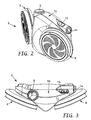
- Fig. 2 is a perspective view from the front of one form of blower unit for a PAPR system
- Fig. 3 is a top view of the blower unit
- Fig. 5 is a back view of the blower unit, the unit being shown mounted on a belt;
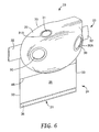
- Fig. 6 is a perspective view from the front of a pouch for the blower unit of Fig. 2;
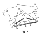
- Fig. 8 is a perspective view of the pouch from the back, the pouch being shown partly-open;
- Fig. 9 is an exploded view of the pouch, showing (on a smaller scale) the various layers from which the pouch is assembled; '
- Fig. 10 and Fig. 11 are, respectively, a back view and a side view of the pouch illustrating a step in the process of closing the pouch;
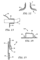
- Fig. 12 is a diagrammatic cross-section of a seal between the pouch and the air outlet of the blower unit
- Fig. 13 is a diagrammatic illustration of another seal between the pouch and the belt of the blower unit.
- Fig. 14 and Fig. 15 are cross-sections of pneumatic seals that are formed in the pouch.
- Fig. 1 illustrates diagrammatically the main components of a powered air purifying respirator (PAPR) system 1.
- System 1 is generally described in copending Application Serial No. 10/121,306 entitled PERSONAL CONTAINMENT SYSTEM WITH ISOLATED BLOWER, filed 12 April 2002.
- the system includes a respiratory mask 2 (which is illustrated as a hood but could be of any suitable type) and a blower unit 3 that supplies filtered air to the mask through a breathing tube 4 connected to the air outlet 5 of the unit.
- the blower unit 3 comprises a blower 6 powered by an electrical source 7 (typically a battery pack that is contained within the unit 3), and has at least one air inlet 8 to which a filter cartridge 9 is attached.
- an electrical source 7 typically a battery pack that is contained within the unit 3
- the blower 6 draws air into the unit 3 through the filter 9 at the air inlet 8, and delivers the filtered air continuously to the respiratory mask 2 via the breathing tube 4, as indicated by the arrows.
- Spent air within the mask 2 is expelled, for example through a suitably-positioned vent, duct or valve (not shown), by the incoming filtered air which enters the mask at a positive pressure relative to the ambient pressure in the environment in which the PAPR is being used.
- the or each filter cartridge 9 is removably-attached to the blower unit 3 so that it can be replaced when its useful life expires.
- blower unit 3 suitable for use in a PAPR system is shown in Fig. 2 to Fig. 5.
- the unit has a housing 10 on the front of which are two air inlets 8 (Fig. 4 ) to which, in use, are attached respective filter cartridges 9 (Fig. 2 and Fig. 3).
- the air outlet 5 is located at the top of the blower unit 3 and is provided with a connection 11 (shown only in Fig. 5) for the attachment of the breathing tube 4 (not shown in Fig. 2 to Fig. 5).
- a belt track 16 is formed in the back of the housing 10 to receive a belt 17, as shown in Fig. 5, by means of which the blower unit 3 can be mounted at the user's waist, typically at the back of the body.
- the belt 17 is intended to be attached to a second belt (not shown) shaped to provide increased support for the blower unit 3 adjacent the wearer's back.
- the back of the blower unit (which, in use, would be adjacent the back of the user) is generally flat.
- each filter cartridge 9 is sealingly-engaged in the respective air inlet 8 of the housing 10 by means of a threaded connection, preferably one that permits rapid connection of the cartridge to the blower unit 3.
- the threaded connection is supplemented by a click-lock feature that prevents accidental disengagement of the filter cartridge from the blower unit and also provides an indication to the user that the cartridge has been properly installed.
- blower is preferably used together with a personal protective suit equipped with a partial flow restriction between the hood portion and body portion of the suit as described in U.S. Application Serial No. 10/263,892 entitled PERSONAL PROTECTIVE SUIT WITH PARTIAL FLOW RESTRICTION, filed 3 October 2002.
- the blower unit 3 In normal use, the blower unit 3 is mounted at the waist of the PAPR user, as already described, and will be exposed to the environment in which the user finds himself.
- the filter cartridges 9 are selected, taking account of that environment, to ensure that they will remove any respiratory hazards from the air that is drawn into the unit 3 by the blower 6.
- it is desirable (and, in some cases, essential) to be able to protect the blower unit 3 from the environment in which the PAPR user finds himself and a method by which that may be achieved will be described below.
- One circumstance in which protection of the unit 3 from the environment may be essential is when the environment contains a potentially explosive substance (gas or dust) which should not be allowed to come into proximity with, for example, the electrical components within the unit, for example via the battery compartment 12.
- a circumstance in which isolation of the unit 3 from the environment may be highly desirable is when the environment contains a contaminant (e.g. a chemical or a biological substance) that would necessitate thorough cleaning of the unit 3 if the latter were exposed to it during use.
- a contaminant e.g. a chemical or a biological substance
- a pouch 20 which, when closed, forms a sealed enclosure around the unit.
- the pouch 20 is indicated diagrammatically in dotted lines in Fig. 1.
- a pouch 20 that is suitable for use with the blower unit of Fig. 2 to Fig. 5 will now be described with reference to Fig. 6 to Fig. 12.
- the pouch 20 is formed from a flexible polymeric material.
- the material is transparent but, for clarity, is illustrated in the drawings as if it were opaque so that features that would normally be visible through the pouch do not appear.
- the pouch 20 has the general form of an elongate bag open at its lower end 21 and closed at its upper end 22.
- the upper part 23 of the pouch 20, adjacent the closed end 22, has a shape that corresponds to the external shape of the blower unit while the lower part (or skirt) 24 is generally flat when the pouch is in an un-opened condition.
- a V-shaped pleat 25 is formed in the back of the pouch (see Fig. 8) to facilitate the insertion of the blower unit 3, as will be described below.
- the pouch 20 comprises a front panel 26 and a back panel 27, together with an internal front panel 28 and two internal back panels 29 (see Fig. 9) that are used to form the pleat 25.
- the upper part of the front panel 26 is shaped by thermo-forming to fit over the front, top and bottom surfaces of the housing 10 of the blower unit 3, including the on/off button 14 and the indicator panel 15, and has apertures 30 positioned to correspond to the location of the air inlets 8 of the blower unit, and an aperture 31 positioned to correspond to the location of the air outlet 5.
- a pneumatic seal 30A is formed around the periphery of each of the apertures 30, and the construction and purpose of these seals will be described in greater detail below.
- a raised lip 31A is formed in the pouch around the aperture 31, the purpose of which will also be described below.
- the back panel 27 of the pouch 20 is flat, with a peripheral shape that corresponds to that of the front panel, to which it is joined (except at the lower end and at the outer ends of the arms 32) by a peripheral welded seam 33.
- the back panel 27 of the pouch is slit from the lower edge almost to the top, as indicated at 34.
- the two internal back panels 29 (each in the shape of a right-angled triangle equivalent to one half of the internal front panel 28) are joined to the internal front panel 28 along their longest sides 35 and to the back panel 27 on each side of the slit 34.
- the joined internal panels 28, 29 are also secured to the back panel 27 at the top of the slit 34, thus forming the pleat 25.
- the front panel 26 extends beyond both the back panel 27 and the internal panels 28, 29 at the lower end 21 of the pouch and, on the inside surface of the extension, carries a strip 36 that extends the width of the front panel and comprises one part of a hook-and-loop fastener.
- Strips 37 that constitute the other part of the hook-and-loop fastener are located along the lower end of each half of the back panel 27, on outer surface of the latter.
- a pneumatic seal 38 Immediately above the strip 36 on the inside surface of the front panel 26 is a pneumatic seal 38, the construction of which will be described below. The purpose of the hook-and-loop fastener strips 36, 37 and the pneumatic seal 38 will be described below.
- the lower end 21 of the pouch (including the pleat 25) is opened up and the blower unit 3 (without the filter cartridges 9 and the belt 17) is pushed inside towards the upper end 22 of the pouch until it is correctly located in the shaped portion 23 with the air outlet 5 extending out of the top of the pouch through the aperture 31.
- the air inlets 8 of the blower unit will be aligned with the apertures 30 in the front panel of the pouch.
- the belt 17 is then threaded into the pouch through one of the arms 32, along the belt track 16 of the blower unit 3, and out through the other arm 32 so that it extends out of the pouch on both sides and can be used to mount the blower unit at the waist of the wearer in the normal way.
- the open end 21 of the pouch is then closed and sealed by means of the hook-and-loop closures 36, 37 and the pneumatic seal 38 as will be described below, and the skirt portion 24 is folded up behind the upper part of the back panel 27 of the pouch as indicated by the arrow X in Fig.11.
- An indicator line 24A may be provided on the back panel 27 to show the preferred location of the fold, if desired.
- Filter cartridges 9 are attached to the air inlets 8 of the blower unit 3 from the outside of the pouch, and the blower unit can then be used in a PAPR in the normal way.
- the construction of the pouch ensures that no undesirable particulate or gaseous materials (such as dust, fumes, vapours, or chemical/biological contaminants, depending on the circumstances) can enter the pouch at any point, particularly around the air outlet 5 of the blower unit; or around the belt 17; or around the air inlets 8 of the blower; or through the lower end 21 of the pouch.
- undesirable particulate or gaseous materials such as dust, fumes, vapours, or chemical/biological contaminants, depending on the circumstances
- the aperture 31 in the pouch and the surrounding upstanding lip 31A are formed with a diameter that is slightly smaller than the external diameter of the air outlet. Consequently, the pouch material must be stretched to enable the air outlet 5 to be inserted through the aperture 31 and will then shrink back, causing the lip 31A to form a seal against the external surface of the air outlet (see Fig. 12). Through an appropriate choice of the diameter of the aperture 31 and the height of the lip 31A, this seal can prevent the entry of particulate or gaseous contaminants into the pouch around the air outlet 5.
- the length of the arms 32 (provided that they are a snug fit around the belt 17, as shown in Fig. 13) the entry of particulate or gaseous contaminants into the pouch around the belt 17 can also be prevented.
- the belt 17 is 4 or 5 cms wide, it has been found that a length of 2 or 3 cms for the arms 32 is generally sufficient.
- the pneumatic seal 38 is arranged to form a labyrinth seal within the skirt 24 of the pouch when the latter is closed.
- An enlarged cross-section through the seal 38 is shown in Fig. 15.
- the seal comprises a tuck 42 secured by a weld 44 in the material of the front panel 26 immediately above the fastener strip 36, the tuck resulting in the formation of a closed air-filled cushion of material 46 on the inside of the front panel 26.
- the pouch is closed in the following way after the blower unit 3 has been placed inside.
- the skirt 24 of the pouch is first flattened so that the front and back panels 26, 27 lie one on top of the other with the flattened pleat-forming layers 28, 29 between them.
- the lower extension of the front panel 26, carrying the fastener strip 36 is then folded backwards and upwards (as indicated by the arrow Y in Fig. 11) along the weld 44, which functions as a hinge, and is pressed into engagement with the fastener strips 37 on the back of the pouch.
- the hook-and-loop fastener strips 36, 37 thus close the pouch 20 and trap the air-filled cushion 46 inside the folded lower end of the skirt 24, where it will contact the adjacent surfaces of the pouch and form a labyrinth seal to prevent the entry of undesirable material into the pouch at this end.
- the pouch 20 is formed from any suitable polymeric material that can be thermo-formed to provide the shaped upper part of the front panel, and can be welded to form the seams between the various layers.
- the pouch can be formed completely from a transparent material so that the whole of the blower unit 3 can be seen through the pouch.
- the pouch can be formed from an opaque material with transparent inserts so that only certain parts of the blower unit (especially the on/off switch 14 and the indicator panel 15) are visible.
- a suitable material for the pouch 20 is a polyurethane material and, if desired, the shaped upper part of the front panel can be formed from a thicker version of the material than the rest of the pouch to provide enhanced protection against damage for the outwardly-facing surfaces of the blower unit when the latter is in use.
- the layers of the pouch may all be formed from a polyurethane ester material having a density of 1.15 g/cm3, except the shaped upper part of the front panel which has a density of 1.21 g/cm3 and a higher tear resistance. In that case, the shaped upper part 23 of the front panel would be welded to the skirt part 24, as indicated by the weld line 48 in Fig. 6 and Fig. 7.
- a blower unit 3 that is not, in itself, intrinsically-safe can be provided with protection to a prescribed level against the ingress of a potentially explosive material in the form of gas or dust. Before the blower unit is inserted in the pouch it should not already be contaminated (e.g. previously exposed to dust) since that could render the pouch useless.
- the various layers of the pouch could be joined together in different ways and, in the case of the pleat 25 , at least some of the seams could be replaced by folds.
- alternative forms of seals and closures could be used to prevent the entry of undesirable materials into the pouch following insertion of the blower unit.
- the filter cartridges 9 could be attached to the blower unit 3 in the manner described in the above-mentioned US Application Serial No. 10/121306 filed 1,2 April 2002.
- the belt 17 could be attached to the pouch during assembly of the latter, or formed as an integral part of the front or rear panel 26, 27 of the pouch.
- the pouch could be formed as part of a garment (for example, a protective suit) that is worn by the user.
Landscapes
- Health & Medical Sciences (AREA)
- General Health & Medical Sciences (AREA)
- Business, Economics & Management (AREA)
- Emergency Management (AREA)
- Pulmonology (AREA)
- Toxicology (AREA)
- Respiratory Apparatuses And Protective Means (AREA)
- Air Bags (AREA)
- Cooling Or The Like Of Electrical Apparatus (AREA)
- Making Paper Articles (AREA)
Claims (15)
- Beutel für die Gebläseeinheit eines Luftreinigungsatemschutzsystems mit Gebläse, wobei die Gebläseeinheit einer Art ist, die(a) einen Lufteinlass, mit dem eine Filterpatrone lösbar verbunden werden kann,(b) einen Luftauslass, mit dem ein Atemrohr des Atemschutzsystems lösbar verbunden werden kann, und(c) ein Gebläse, das dahingehend wirkt, durch den Lufteinlass Luft in die Einheit zu saugen und gefilterte Luft an den Luftauslass zu liefern, aufweist,wobei der Beutel(i) eine verschließbare Hauptöffnung, durch die die Gebläseeinheit in den Beutel eingeführt werden kann,(ii) eine Lufteinlassöffnung, die derart positioniert ist, dass sie mit dem Lufteinlass des Gebläses einrastet und die Verbindung der Filterpatrone damit gestattet,(iii) eine Luftauslassöffnung, die derart positioniert ist, dass sie mit dem Luftauslass des Gebläses einrastet und die Verbindung des Atemrohrs damit gestattet, und(iv) jeweilige Dichtungen für jede der Öffnungen aufweist,wobei die Dichtungen derart ausgelegt sind, dass die Dichtungen den Durchgang von teilchen- oder gasförmigem Material durch die Öffnungen in den Beutel erschweren oder verhindern, wenn der Beutel geschlossen ist und die Gebläseeinheit sich im Beutel befindet und mit dem Atemschutzsystem verbunden ist.
- Beutel nach Anspruch 1, wobei sich die Hauptöffnung an einem Ende des Beutels befindet, wobei das andere Ende des Beutels verschlossen ist und eine zur Aufnahme der Gebläseeinheit geeignete Form hat und die Lufteinlass- und -auslassöffnungen aufweist.
- Beutel nach Anspruch 1, wobei die Dichtung der Lufteinlassöffnung die Einlassöffnung umgibt und derart angeordnet ist, dass sie gegen die Filterpatrone abdichtet, und wobei die Dichtung der Lufteinlassöffnung ein luftgefülltes Kissen aufweist.
- Beutel nach Anspruch 1, wobei die Luftauslassöffnung eine solche Form hat, dass sie um einen sich von dem Luftauslass der Gebläseeinheit erstreckenden Auslassanschluss passt und daran abdichtet.
- Beutel nach Anspruch 2, wobei das eine Ende des Beutels zu einer Labyrinthdichtung gegen das Eindringen von teilchen- oder gasförmigem Material in den Beutel gefaltet werden kann.
- Beutel nach Anspruch 1, wobei die Gebläseeinheit ein Fach für einen Akkupack zur Versorgung des Gebläses mit Strom aufweist, wobei das Fach durch die Hauptöffnung des Beutels zugänglich ist.
- Beutel nach Anspruch 1, wobei der Beutel aus einem Material gebildet ist, dank dessen der Steuerschalter der Gebläseeinheit von außerhalb des Beutels durch das Material hindurch betätigt werden kann.
- Beutel nach Anspruch 1, wobei der Beutel aus einem Material gebildet ist, durch das hindurch die Steuerungen und Anzeigen der Gebläseeinheit sichtbar sind.
- Beutel nach Anspruch 1, wobei der Beutel eine derartige Form hat, dass er an einem Gürtel angebracht werden kann, mit dem die Gebläseeinheit an der Taille eines Verwenders positioniert werden kann und wobei der Beutel mit Eingangs- und Ausgangsöffnungen für den Gürtel ausgebildet ist, wobei die Gürtelöffnungen eine derartige Form haben, dass sie den Gürtel aufnehmen und um diesen herum passen, und länglich sind, um das Eindringen von teilchen- oder gasförmigem Material in den Beutel zu verhindern, wenn Letzterer am Gürtel angebracht ist.
- Verfahren zum Schutz der Gebläseeinheit eines Luftreinigungsatemschutzsystems mit Gebläse gegen das Eindringen von teilchen- oder gasförmigem Material in die Einheit, wobei die Gebläseeinheit einer Art ist, die(a) einen Lufteinlass, mit dem eine Filterpatrone lösbar verbunden werden kann,(b) einen Luftauslass, mit dem ein Atemrohr des Atemschutzsystems lösbar verbunden werden kann, und(c) ein Gebläse, das dahingehend wirkt, durch den Lufteinlass Luft in die Einheit zu saugen und gefilterte Luft an den Luftauslass zu liefern, aufweist,wobei das Verfahren folgende Schritte aufweist:(i) Platzieren der Gebläseeinheit in einen Beutel nach einem der vorhergehenden Ansprüche,(ii) Verbinden des Lufteinlasses mit der Filterpatrone durch eine Öffnung in dem Beutel,(iii) Verbinden des Luftauslasses mit dem Atemrohr durch eine Öffnung in dem Beutel und(iv) Versehen der Öffnungen im Beutel mit Dichtungen, um den Durchgang von teilchen- oder gasförmigem Material durch die Öffnungen in den Beutel zu erschweren oder zu verhindern.
- Verfahren zum Schutz der Gebläseeinheit eines Luftreinigungsatemschutzsystems mit Gebläse gegen das Eindringen von teilchen- oder gasförmigem Material in die Einheit mit dem Schritt des Platzierens der Einheit in einen Beutel nach Anspruch 1.
- Atemschutzsystem, daseine Atemmaske,eine Gebläseeinheit mit einem Lufteinlass, einem Luftauslass und einem Gebläse, das dahingehend wirkt, durch den Lufteinlass Luft in die Einheit zu saugen und Luft an den Luftauslass zu liefern,einen Beutel nach einem der Ansprüche 1 bis 9, in dem sich die Gebläseeinheit befindet,eine Filterpatrone, die durch eine Öffnung in dem Beutel lösbar mit dem Lufteinlass der Gebläseeinheit verbunden ist, undein Atemrohr, das an einem Ende durch eine Öffnung im Beutel lösbar mit dem Luftauslass der Gebläseeinheit und am anderen Ende mit der Atemmaske verbunden ist, aufweist,wobei die Öffnungen in dem Beutel mit Dichtungen versehen sind, die den Durchgang von teilchen- oder gasförmigem Material durch die Öffnungen in den Beutel erschweren oder verhindern.
- System nach Anspruch 12, wobei der Luftauslass der Gebläseeinheit ein Verbindungselement aufweist, das sich durch den Beutel erstreckt und mit dem Atemrohr verbunden ist.
- System nach Anspruch 12, wobei ein Akkupack zur Speisung der Gebläseeinheit durch Öffnen des Beutels, jedoch ohne die Gebläseeinheit daraus zu entfernen, zugänglich ist.
- Luftreinigungsatemschutzsystem, daseine Atemmaske,eine Gebläseeinheit mit einem Lufteinlass, einem Luftauslass und einem Gebläse, das dahingehend wirkt, durch den Lufteinlass Luft in die Einheit zu saugen und Luft an den Luftauslass zu liefern,eine Filterpatrone, die lösbar mit dem Lufteinlass der Gebläseeinheit verbunden ist, undein Atemrohr, das an einem Ende lösbar mit dem Luftauslass der Gebläseeinheit und am anderen Ende mit der Atemmaske verbunden ist, aufweist,wobei sich die Gebläseeinheit des Systems in einem Beutel nach Anspruch 1 befindet, um den Durchgang von teilchen- oder gasförmigem Material in die Gebläseeinheit zu erschweren oder zu verhindern.
Applications Claiming Priority (5)
| Application Number | Priority Date | Filing Date | Title |
|---|---|---|---|
| US263807 | 1994-06-22 | ||
| US121306 | 2002-04-12 | ||
| US10/121,306 US20030192536A1 (en) | 2002-04-12 | 2002-04-12 | Personal containment system with isolated blower |
| US10/263,807 US6823867B2 (en) | 2002-04-12 | 2002-10-03 | Pouch for the blower unit of a powered air purifying respirator |
| PCT/US2003/008631 WO2003086545A1 (en) | 2002-04-12 | 2003-03-19 | Pouch for the blower unit of a powered air purifying respirator |
Publications (2)
| Publication Number | Publication Date |
|---|---|
| EP1494761A1 EP1494761A1 (de) | 2005-01-12 |
| EP1494761B1 true EP1494761B1 (de) | 2006-08-02 |
Family
ID=29253968
Family Applications (1)
| Application Number | Title | Priority Date | Filing Date |
|---|---|---|---|
| EP03716737A Expired - Lifetime EP1494761B1 (de) | 2002-04-12 | 2003-03-19 | Beutel für das gebläsesystem eines angetriebenen luftreinigungsbeatmungssystems |
Country Status (8)
| Country | Link |
|---|---|
| US (1) | US6823867B2 (de) |
| EP (1) | EP1494761B1 (de) |
| AT (1) | ATE334726T1 (de) |
| AU (1) | AU2003220432A1 (de) |
| CA (1) | CA2481769A1 (de) |
| DE (1) | DE60307253T2 (de) |
| ES (1) | ES2270000T3 (de) |
| WO (1) | WO2003086545A1 (de) |
Families Citing this family (26)
| Publication number | Priority date | Publication date | Assignee | Title |
|---|---|---|---|---|
| US6796304B2 (en) * | 2002-04-12 | 2004-09-28 | 3M Innovative Properties Company | Personal containment system with sealed passthrough |
| USD497667S1 (en) | 2002-10-03 | 2004-10-26 | 3M Innovative Properties Company | Pouch |
| USD615732S1 (en) | 2003-07-31 | 2010-05-18 | West Coast Trends, Inc. | Pleated pocket device |
| US20050025399A1 (en) * | 2003-07-31 | 2005-02-03 | West Coast Trends, Inc., A California Corporation | Pleated pocket device |
| US7198079B2 (en) * | 2003-09-09 | 2007-04-03 | Tvi Corporation | Liquid delivery system of gas mask |
| US8584676B2 (en) * | 2003-11-19 | 2013-11-19 | Immediate Response Technologies | Breath responsive filter blower respirator system |
| US7273052B2 (en) * | 2003-12-11 | 2007-09-25 | Tvi Corporation | Pneumatic sealing system for protection masks |
| US7690379B2 (en) * | 2004-06-01 | 2010-04-06 | Branch, Banking and Trust Company | Pressure indicator for positive pressure protection masks |
| US7469699B2 (en) * | 2004-09-03 | 2008-12-30 | Tvi Corporation | Thin profile air purifying blower unit and filter cartridges, and method of use |
| US7458390B2 (en) * | 2005-12-21 | 2008-12-02 | Tvi Corporation | Breath controlled air inlet for blower |
| US20070297789A1 (en) * | 2006-06-22 | 2007-12-27 | Brune Guenter W | Device and method for contaminant free lens changes of a digital camera |
| US8535464B2 (en) | 2007-04-05 | 2013-09-17 | Avery Dennison Corporation | Pressure sensitive shrink label |
| US8282754B2 (en) | 2007-04-05 | 2012-10-09 | Avery Dennison Corporation | Pressure sensitive shrink label |
| AU2009251721B2 (en) * | 2008-04-04 | 2012-05-03 | 3M Innovative Properties Company | Air filtration device |
| CA135169S (en) * | 2009-11-02 | 2010-12-21 | Scott Health & Safety Ltd | Blower unit for breathing mask |
| BR122014017821A2 (pt) | 2010-01-28 | 2019-07-09 | Avery Dennison Corporation | Sistema para aplicação de rótulos em artigos |
| US8899227B2 (en) | 2011-12-15 | 2014-12-02 | 3M Innovative Properties Company | Air filtration device having subsections lacking fluid communication |
| US8887719B2 (en) | 2011-12-15 | 2014-11-18 | 3M Innovative Properties Company | Air filtration device having tuned air distribution system |
| DE102013000809A1 (de) * | 2013-01-17 | 2014-07-17 | Dräger Safety AG & Co. KGaA | Tragesystem für ein Gebläsefiltergerät, Gebläsefiltergerät sowie Gebläsefiltersystem |
| JP6455653B2 (ja) * | 2013-12-26 | 2019-01-23 | 株式会社メトラン | フィルター構造 |
| CN103877681A (zh) * | 2014-02-21 | 2014-06-25 | 李滢 | 一体化太阳能空气净化面具模块 |
| WO2017039497A1 (en) * | 2015-08-31 | 2017-03-09 | Maquet Critical Care Ab | Fan-driven respiratory assistance apparatus with reversed fan-motor assembly |
| DE202018103159U1 (de) * | 2018-06-06 | 2019-09-09 | Tesimax-Altinger Gmbh | Schutzanzug und Schutzanordnung |
| WO2021195354A1 (en) * | 2020-03-26 | 2021-09-30 | Alexander Werjefelt | Pathogen protection device |
| TWM604134U (zh) * | 2020-06-17 | 2020-11-21 | 林永吉 | 空氣濾清防護裝置及防護衣 |
| US20230015547A1 (en) * | 2021-07-13 | 2023-01-19 | Jamie Tart | Filtration enclosure for ventilation bags |
Family Cites Families (19)
| Publication number | Priority date | Publication date | Assignee | Title |
|---|---|---|---|---|
| DE156463C (de) | ||||
| US3446420A (en) * | 1968-02-08 | 1969-05-27 | American Velcro Inc | Flexible mouth container |
| US3768467A (en) * | 1970-06-18 | 1973-10-30 | Community Gin Co | Life preserver bubble |
| US3786809A (en) * | 1972-09-07 | 1974-01-22 | Tecna Corp | Device for treating infants having breathing difficulties |
| FR2565662B1 (fr) | 1984-06-08 | 1986-09-19 | Fabrications Indles Sa | Robinet destine notamment a l'alimentation en air sain de vetements ou combinaisons etanches. |
| DE3660849D1 (en) * | 1985-02-08 | 1988-11-10 | Josef Ponn | Life equipment intended to the survival of a person in toxic atmosphere |
| US4620538A (en) * | 1985-03-19 | 1986-11-04 | The United States Of America As Represented By The Secretary Of The Air Force | Light-weight oxygen delivery hood assembly for hyperbaric chamber |
| JPH0649085B2 (ja) * | 1985-11-15 | 1994-06-29 | ブリティッシュ・テクノロジー・グループ・リミテッド | 自蔵式電動ファン付粉じん用呼吸保護具 |
| GB8620003D0 (en) * | 1986-08-16 | 1986-09-24 | Arbuthnoit R D | Accessory device |
| DE3825621A1 (de) | 1988-07-28 | 1990-02-01 | Auergesellschaft Gmbh | Gasdichter schutzanzug mit einem chemikalsauerstoff-atemschutzgeraet |
| US4899740A (en) * | 1989-01-17 | 1990-02-13 | E. D. Bullard Company | Respirator system for use with a hood or face mask |
| US5003974A (en) * | 1989-10-27 | 1991-04-02 | Mou Lin Her | First-aid gas mask |
| FR2669541B1 (fr) | 1990-11-27 | 1993-02-19 | Intertechnique Sa | Equipement de protection a scaphandre. |
| FR2669542B1 (fr) | 1990-11-27 | 1993-02-19 | Intertechnique Sa | Equipement individuel de protection a scaphandre et alimentation autonome. |
| CA2172929A1 (en) * | 1996-03-28 | 1997-09-29 | Yoshimi Kano | Portable enclosure system and method for providing a suitable breathing environment therein |
| US6014971A (en) * | 1997-08-15 | 2000-01-18 | 3M Innovative Properties Company | Protective system for face and respiratory protection |
| US6321764B1 (en) * | 1998-12-21 | 2001-11-27 | Iit Research Institute | Collapsible isolation apparatus |
| AUPQ664400A0 (en) | 2000-04-03 | 2000-05-04 | Safety Equipment Australia Pty Ltd | Ventilation system for protective suit |
| US6575165B1 (en) * | 2000-08-03 | 2003-06-10 | 3M Innovative Properties Company | Apparatus and method for breathing apparatus component coupling |
-
2002
- 2002-10-03 US US10/263,807 patent/US6823867B2/en not_active Expired - Lifetime
-
2003
- 2003-03-19 DE DE60307253T patent/DE60307253T2/de not_active Expired - Fee Related
- 2003-03-19 ES ES03716737T patent/ES2270000T3/es not_active Expired - Lifetime
- 2003-03-19 AT AT03716737T patent/ATE334726T1/de not_active IP Right Cessation
- 2003-03-19 EP EP03716737A patent/EP1494761B1/de not_active Expired - Lifetime
- 2003-03-19 AU AU2003220432A patent/AU2003220432A1/en not_active Abandoned
- 2003-03-19 WO PCT/US2003/008631 patent/WO2003086545A1/en not_active Ceased
- 2003-03-19 CA CA002481769A patent/CA2481769A1/en not_active Abandoned
Also Published As
| Publication number | Publication date |
|---|---|
| DE60307253T2 (de) | 2007-07-05 |
| EP1494761A1 (de) | 2005-01-12 |
| WO2003086545A1 (en) | 2003-10-23 |
| ES2270000T3 (es) | 2007-04-01 |
| AU2003220432A1 (en) | 2003-10-27 |
| US20030192541A1 (en) | 2003-10-16 |
| ATE334726T1 (de) | 2006-08-15 |
| US6823867B2 (en) | 2004-11-30 |
| CA2481769A1 (en) | 2003-10-23 |
| DE60307253D1 (de) | 2006-09-14 |
Similar Documents
| Publication | Publication Date | Title |
|---|---|---|
| US6823867B2 (en) | Pouch for the blower unit of a powered air purifying respirator | |
| EP1494759B1 (de) | Persönliches eindämmungssystem mit abgedichteter durchfuhr | |
| EP0078110B1 (de) | Luftatmungsgerät mit Motorantrieb und Filtereinsatz für dieses Gerät | |
| US5022900A (en) | Forced ventilation filtration device | |
| US6763835B1 (en) | Chemical/biological special operations mask | |
| EP1494760B1 (de) | Persönlicher schutzanzug mit einer partiellen strömungsbegrenzung | |
| RU2372120C2 (ru) | Портативная воздухоочистительная система, использующая фильтры, закрытые кожухом | |
| JP5362547B2 (ja) | 呼吸用保護装置 | |
| RU2169595C2 (ru) | Способ (варианты) и устройство для защиты от вдыхания дыма при чрезвычайных ситуациях | |
| EP1865854B1 (de) | Kombiniertes luftzufuhr-/luftreinigungssystem | |
| MXPA97001534A (en) | Process and emergency system for the protection of inhalation of h | |
| US20030192536A1 (en) | Personal containment system with isolated blower | |
| US6553989B1 (en) | Self-contained breathing apparatus with emergency filtration device | |
| HK1107787B (en) | Portable air-purifying system utilizing enclosed filters | |
| HK1107753B (en) | Combined air-supplying/air-purifying system |
Legal Events
| Date | Code | Title | Description |
|---|---|---|---|
| PUAI | Public reference made under article 153(3) epc to a published international application that has entered the european phase |
Free format text: ORIGINAL CODE: 0009012 |
|
| 17P | Request for examination filed |
Effective date: 20041020 |
|
| AK | Designated contracting states |
Kind code of ref document: A1 Designated state(s): AT BE BG CH CY CZ DE DK EE ES FI FR GB GR HU IE IT LI LU MC NL PT RO SE SI SK TR |
|
| AX | Request for extension of the european patent |
Extension state: AL LT LV MK |
|
| GRAP | Despatch of communication of intention to grant a patent |
Free format text: ORIGINAL CODE: EPIDOSNIGR1 |
|
| GRAS | Grant fee paid |
Free format text: ORIGINAL CODE: EPIDOSNIGR3 |
|
| GRAA | (expected) grant |
Free format text: ORIGINAL CODE: 0009210 |
|
| AK | Designated contracting states |
Kind code of ref document: B1 Designated state(s): AT BE BG CH CY CZ DE DK EE ES FI FR GB GR HU IE IT LI LU MC NL PT RO SE SI SK TR |
|
| PG25 | Lapsed in a contracting state [announced via postgrant information from national office to epo] |
Ref country code: IT Free format text: LAPSE BECAUSE OF FAILURE TO SUBMIT A TRANSLATION OF THE DESCRIPTION OR TO PAY THE FEE WITHIN THE PRESCRIBED TIME-LIMIT;WARNING: LAPSES OF ITALIAN PATENTS WITH EFFECTIVE DATE BEFORE 2007 MAY HAVE OCCURRED AT ANY TIME BEFORE 2007. THE CORRECT EFFECTIVE DATE MAY BE DIFFERENT FROM THE ONE RECORDED. Effective date: 20060802 Ref country code: CH Free format text: LAPSE BECAUSE OF FAILURE TO SUBMIT A TRANSLATION OF THE DESCRIPTION OR TO PAY THE FEE WITHIN THE PRESCRIBED TIME-LIMIT Effective date: 20060802 Ref country code: SK Free format text: LAPSE BECAUSE OF FAILURE TO SUBMIT A TRANSLATION OF THE DESCRIPTION OR TO PAY THE FEE WITHIN THE PRESCRIBED TIME-LIMIT Effective date: 20060802 Ref country code: NL Free format text: LAPSE BECAUSE OF FAILURE TO SUBMIT A TRANSLATION OF THE DESCRIPTION OR TO PAY THE FEE WITHIN THE PRESCRIBED TIME-LIMIT Effective date: 20060802 Ref country code: RO Free format text: LAPSE BECAUSE OF FAILURE TO SUBMIT A TRANSLATION OF THE DESCRIPTION OR TO PAY THE FEE WITHIN THE PRESCRIBED TIME-LIMIT Effective date: 20060802 Ref country code: LI Free format text: LAPSE BECAUSE OF FAILURE TO SUBMIT A TRANSLATION OF THE DESCRIPTION OR TO PAY THE FEE WITHIN THE PRESCRIBED TIME-LIMIT Effective date: 20060802 Ref country code: FI Free format text: LAPSE BECAUSE OF FAILURE TO SUBMIT A TRANSLATION OF THE DESCRIPTION OR TO PAY THE FEE WITHIN THE PRESCRIBED TIME-LIMIT Effective date: 20060802 Ref country code: BE Free format text: LAPSE BECAUSE OF FAILURE TO SUBMIT A TRANSLATION OF THE DESCRIPTION OR TO PAY THE FEE WITHIN THE PRESCRIBED TIME-LIMIT Effective date: 20060802 Ref country code: SI Free format text: LAPSE BECAUSE OF FAILURE TO SUBMIT A TRANSLATION OF THE DESCRIPTION OR TO PAY THE FEE WITHIN THE PRESCRIBED TIME-LIMIT Effective date: 20060802 Ref country code: AT Free format text: LAPSE BECAUSE OF FAILURE TO SUBMIT A TRANSLATION OF THE DESCRIPTION OR TO PAY THE FEE WITHIN THE PRESCRIBED TIME-LIMIT Effective date: 20060802 Ref country code: CZ Free format text: LAPSE BECAUSE OF FAILURE TO SUBMIT A TRANSLATION OF THE DESCRIPTION OR TO PAY THE FEE WITHIN THE PRESCRIBED TIME-LIMIT Effective date: 20060802 |
|
| REG | Reference to a national code |
Ref country code: GB Ref legal event code: FG4D |
|
| REG | Reference to a national code |
Ref country code: CH Ref legal event code: EP |
|
| REG | Reference to a national code |
Ref country code: IE Ref legal event code: FG4D |
|
| REF | Corresponds to: |
Ref document number: 60307253 Country of ref document: DE Date of ref document: 20060914 Kind code of ref document: P |
|
| PG25 | Lapsed in a contracting state [announced via postgrant information from national office to epo] |
Ref country code: SE Free format text: LAPSE BECAUSE OF FAILURE TO SUBMIT A TRANSLATION OF THE DESCRIPTION OR TO PAY THE FEE WITHIN THE PRESCRIBED TIME-LIMIT Effective date: 20061102 Ref country code: BG Free format text: LAPSE BECAUSE OF FAILURE TO SUBMIT A TRANSLATION OF THE DESCRIPTION OR TO PAY THE FEE WITHIN THE PRESCRIBED TIME-LIMIT Effective date: 20061102 Ref country code: DK Free format text: LAPSE BECAUSE OF FAILURE TO SUBMIT A TRANSLATION OF THE DESCRIPTION OR TO PAY THE FEE WITHIN THE PRESCRIBED TIME-LIMIT Effective date: 20061102 |
|
| NLV1 | Nl: lapsed or annulled due to failure to fulfill the requirements of art. 29p and 29m of the patents act | ||
| PG25 | Lapsed in a contracting state [announced via postgrant information from national office to epo] |
Ref country code: PT Free format text: LAPSE BECAUSE OF FAILURE TO SUBMIT A TRANSLATION OF THE DESCRIPTION OR TO PAY THE FEE WITHIN THE PRESCRIBED TIME-LIMIT Effective date: 20070102 |
|
| REG | Reference to a national code |
Ref country code: CH Ref legal event code: PL |
|
| ET | Fr: translation filed | ||
| PGFP | Annual fee paid to national office [announced via postgrant information from national office to epo] |
Ref country code: ES Payment date: 20070326 Year of fee payment: 5 |
|
| PGFP | Annual fee paid to national office [announced via postgrant information from national office to epo] |
Ref country code: GB Payment date: 20070327 Year of fee payment: 5 |
|
| REG | Reference to a national code |
Ref country code: ES Ref legal event code: FG2A Ref document number: 2270000 Country of ref document: ES Kind code of ref document: T3 |
|
| PGFP | Annual fee paid to national office [announced via postgrant information from national office to epo] |
Ref country code: DE Payment date: 20070430 Year of fee payment: 5 |
|
| PLBE | No opposition filed within time limit |
Free format text: ORIGINAL CODE: 0009261 |
|
| STAA | Information on the status of an ep patent application or granted ep patent |
Free format text: STATUS: NO OPPOSITION FILED WITHIN TIME LIMIT |
|
| 26N | No opposition filed |
Effective date: 20070503 |
|
| PGFP | Annual fee paid to national office [announced via postgrant information from national office to epo] |
Ref country code: BE Payment date: 20070430 Year of fee payment: 5 Ref country code: IT Payment date: 20070517 Year of fee payment: 5 |
|
| PG25 | Lapsed in a contracting state [announced via postgrant information from national office to epo] |
Ref country code: MC Free format text: LAPSE BECAUSE OF NON-PAYMENT OF DUE FEES Effective date: 20070331 Ref country code: IE Free format text: LAPSE BECAUSE OF NON-PAYMENT OF DUE FEES Effective date: 20070319 |
|
| PG25 | Lapsed in a contracting state [announced via postgrant information from national office to epo] |
Ref country code: GR Free format text: LAPSE BECAUSE OF FAILURE TO SUBMIT A TRANSLATION OF THE DESCRIPTION OR TO PAY THE FEE WITHIN THE PRESCRIBED TIME-LIMIT Effective date: 20061103 |
|
| PGFP | Annual fee paid to national office [announced via postgrant information from national office to epo] |
Ref country code: FR Payment date: 20070319 Year of fee payment: 5 |
|
| PG25 | Lapsed in a contracting state [announced via postgrant information from national office to epo] |
Ref country code: EE Free format text: LAPSE BECAUSE OF FAILURE TO SUBMIT A TRANSLATION OF THE DESCRIPTION OR TO PAY THE FEE WITHIN THE PRESCRIBED TIME-LIMIT Effective date: 20060802 |
|
| BERE | Be: lapsed |
Owner name: *3M INNOVATIVE PROPERTIES CY Effective date: 20080331 |
|
| GBPC | Gb: european patent ceased through non-payment of renewal fee |
Effective date: 20080319 |
|
| REG | Reference to a national code |
Ref country code: FR Ref legal event code: ST Effective date: 20081125 |
|
| PG25 | Lapsed in a contracting state [announced via postgrant information from national office to epo] |
Ref country code: DE Free format text: LAPSE BECAUSE OF NON-PAYMENT OF DUE FEES Effective date: 20081001 |
|
| PG25 | Lapsed in a contracting state [announced via postgrant information from national office to epo] |
Ref country code: BE Free format text: LAPSE BECAUSE OF NON-PAYMENT OF DUE FEES Effective date: 20080331 |
|
| PG25 | Lapsed in a contracting state [announced via postgrant information from national office to epo] |
Ref country code: FR Free format text: LAPSE BECAUSE OF NON-PAYMENT OF DUE FEES Effective date: 20080331 |
|
| REG | Reference to a national code |
Ref country code: ES Ref legal event code: FD2A Effective date: 20080322 |
|
| PG25 | Lapsed in a contracting state [announced via postgrant information from national office to epo] |
Ref country code: GB Free format text: LAPSE BECAUSE OF NON-PAYMENT OF DUE FEES Effective date: 20080319 |
|
| PG25 | Lapsed in a contracting state [announced via postgrant information from national office to epo] |
Ref country code: ES Free format text: LAPSE BECAUSE OF NON-PAYMENT OF DUE FEES Effective date: 20080322 |
|
| PG25 | Lapsed in a contracting state [announced via postgrant information from national office to epo] |
Ref country code: CY Free format text: LAPSE BECAUSE OF FAILURE TO SUBMIT A TRANSLATION OF THE DESCRIPTION OR TO PAY THE FEE WITHIN THE PRESCRIBED TIME-LIMIT Effective date: 20060802 Ref country code: IT Free format text: LAPSE BECAUSE OF NON-PAYMENT OF DUE FEES Effective date: 20080319 Ref country code: LU Free format text: LAPSE BECAUSE OF NON-PAYMENT OF DUE FEES Effective date: 20070319 |
|
| PG25 | Lapsed in a contracting state [announced via postgrant information from national office to epo] |
Ref country code: HU Free format text: LAPSE BECAUSE OF FAILURE TO SUBMIT A TRANSLATION OF THE DESCRIPTION OR TO PAY THE FEE WITHIN THE PRESCRIBED TIME-LIMIT Effective date: 20070203 Ref country code: TR Free format text: LAPSE BECAUSE OF FAILURE TO SUBMIT A TRANSLATION OF THE DESCRIPTION OR TO PAY THE FEE WITHIN THE PRESCRIBED TIME-LIMIT Effective date: 20060802 |