EP1494878B1 - Procede d'identification de caracteristiques d'un pneu - Google Patents
Procede d'identification de caracteristiques d'un pneu Download PDFInfo
- Publication number
- EP1494878B1 EP1494878B1 EP03717296A EP03717296A EP1494878B1 EP 1494878 B1 EP1494878 B1 EP 1494878B1 EP 03717296 A EP03717296 A EP 03717296A EP 03717296 A EP03717296 A EP 03717296A EP 1494878 B1 EP1494878 B1 EP 1494878B1
- Authority
- EP
- European Patent Office
- Prior art keywords
- growth
- value
- tyre
- values
- dds
- Prior art date
- Legal status (The legal status is an assumption and is not a legal conclusion. Google has not performed a legal analysis and makes no representation as to the accuracy of the status listed.)
- Expired - Lifetime
Links
- 238000000034 method Methods 0.000 title claims abstract description 34
- 238000001514 detection method Methods 0.000 claims description 40
- 230000002123 temporal effect Effects 0.000 abstract 1
- 230000006870 function Effects 0.000 description 11
- 230000000875 corresponding effect Effects 0.000 description 7
- 230000000694 effects Effects 0.000 description 5
- 238000005096 rolling process Methods 0.000 description 4
- 230000001419 dependent effect Effects 0.000 description 3
- 230000015572 biosynthetic process Effects 0.000 description 2
- 238000011156 evaluation Methods 0.000 description 2
- 238000003825 pressing Methods 0.000 description 2
- 238000010586 diagram Methods 0.000 description 1
- 238000009434 installation Methods 0.000 description 1
- 230000004044 response Effects 0.000 description 1
- 238000010972 statistical evaluation Methods 0.000 description 1
- 230000002459 sustained effect Effects 0.000 description 1
Images



Classifications
-
- B—PERFORMING OPERATIONS; TRANSPORTING
- B60—VEHICLES IN GENERAL
- B60C—VEHICLE TYRES; TYRE INFLATION; TYRE CHANGING; CONNECTING VALVES TO INFLATABLE ELASTIC BODIES IN GENERAL; DEVICES OR ARRANGEMENTS RELATED TO TYRES
- B60C23/00—Devices for measuring, signalling, controlling, or distributing tyre pressure or temperature, specially adapted for mounting on vehicles; Arrangement of tyre inflating devices on vehicles, e.g. of pumps or of tanks; Tyre cooling arrangements
- B60C23/06—Signalling devices actuated by deformation of the tyre, e.g. tyre mounted deformation sensors or indirect determination of tyre deformation based on wheel speed, wheel-centre to ground distance or inclination of wheel axle
- B60C23/061—Signalling devices actuated by deformation of the tyre, e.g. tyre mounted deformation sensors or indirect determination of tyre deformation based on wheel speed, wheel-centre to ground distance or inclination of wheel axle by monitoring wheel speed
Definitions
- the invention relates to a method for detecting tire properties in an electronic control unit for motor vehicles.
- New tires can show sustained growth in dynamic rolling circumference up to 1.0% of the rolling circumference, especially when first operated at high speed. It has been shown that the circumferential growth begins above a certain speed and lasts for a certain time. After this time the scope does not grow any further, the new tire growth is completed. Further growth then occurs only with further increase in speed.
- the normal state is first learned. If enough speed values have been evaluated for the statistical evaluation, the learning phase is ended and a learning value is formed. Then begins the comparison phase, in which the actual detection of air pressure loss takes place. In the comparison phase, current values of Ref are collected and averaged. When enough suitable values have been collected, the average size is compared with the pressure loss detection learning value. If the tires are inflated or replaced during the detection phase, this must be reported to the system by hand. But it is also possible that detection means are provided which signal a corresponding change in the tires (DDS reset).
- the method according to the invention is preferably carried out as an algorithm in a vehicle computer, which receives information from the ABS wheel speed sensors via corresponding inputs.
- the algorithm is carried out in a microprocessor-controlled brake control unit, which is in any case connected to the wheel speed sensors.
- this control unit is a control unit for conventional hydraulic brake systems or for newer "brake-by-wire" brake systems, such as the electrohydraulic brake (EHB) or the electromechanical brake (EMB).
- learning values are formed separately for predetermined speed ranges in the DDS algorithm. In this way, speed-dependent effects of the tires can be detected.
- the speed-dependent learning value formation preferably takes place in addition to the known formation of learning values instead of.
- the method according to the invention is particularly easy to carry out if the observed tire growth does not occur simultaneously on all four wheels.
- To determine the wheel at which tire growth occurs it is preferable to evaluate a plurality of differently determined reference values. There are each in the z. B. pagewise, crosswise (diagonal) or axis-wise determined reference values deviations whose joint evaluation, a determination of the wheel position at which tire growth has occurred allows.
- step 101 Fig. 1 , first the system z. As indicated by a reset button or an automatic detection device that a manual pressure change has been made to the tire (eg inflating one or more tires or tire assembly). It now has to be checked whether new tires have been installed at the same time. For this, the new tire detection function is activated after pressing the reset button in step 102. If new tire growth is detected in step 103, in step 104 the pressure loss detection algorithm is deactivated during this time. Upon completion of the new growth of the turf, the DDS algorithm is reactivated.
- a reset button or an automatic detection device that a manual pressure change has been made to the tire (eg inflating one or more tires or tire assembly). It now has to be checked whether new tires have been installed at the same time. For this, the new tire detection function is activated after pressing the reset button in step 102. If new tire growth is detected in step 103, in step 104 the pressure loss detection algorithm is deactivated during this time. Upon completion of the new growth of the turf, the
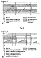
- Fig. 2a the recognition is presented on the basis of four tires in which the new tire growth is already completed.
- Partial image b) shows the corresponding curve when at least one of the tires is a new tire with circumferential growth.
- the velocity axis V is divided into velocity intervals V0 to V7.
- the above-mentioned pressure loss detection method initially records, at intervals individually during a learning phase, the usual rolling characteristics of the vehicle wheels in different driving situations.
- the comparison phase with the actual pressure loss detection is activated.
- the reset button is pressed.
- t1 there is a suspicion of a new tire.
- DDS is switched off.
- Fig. 3 shows in detail the operation of the algorithm for new tire detection in a DDS system.
- the variable v_int indicates the current speed interval. In order to simplify the problem, it can be assumed that the recognition of new mature growth does not occur before the first learning value has been determined.
- Fig. 4 the functionality of the new tire detection is explained in detail.
- the growth of the tire circumference is individually recorded for different speed intervals.
- a comparison is made between the learning value for the instantaneous velocity interval and the value of the preferably averaged or filtered reference value Ref (Y-axis in sub-image a)).
- the number n of the data sets (samples), which were taken into account during the reference value determination in the respective speed interval is plotted.
- Curve 402 represents the course of Ref in tire growth.
- Curve 403 shows the course in the absence of tire growth.
- a counter Z (Y-axis in sub-image b)) is used in each V-interval, which is incremented when the value Ref is greater than the constant A. If the value Ref is smaller than a constant -A, the counter Z is counted down. Curve 404 is the count of Z for tire growth Again, curve 405 refers to the example without tire growth. The time from which the counter is incremented is designated 401. If the counter reaches an upper or lower limit (constant B), as shown in panel b), the "growth detected" flag is set, thus making recognition of tire growth known to the algorithm.
- V i the vehicle is driven a certain time (V i) in a V interval, it is assumed by the algorithm that the NeuNeillwachstum is completed. After expiration of the predetermined time, the flag "growth finished in speed interval V" is set for this purpose.
- Case 1 is, for example, a pressure drop during vehicle standstill after teaching in this speed interval or a very fast pressure loss.
- the counter Z is downsampled in magnitude. This will be the Prevents system from displaying a new tire growth when there is actually a pressure drop.
- the flag "growth detected" is set.
- the counter ZP which is provided for the pressure loss detection, no longer counted.
- a pressure loss warning remains off, as this is only activated when ZP has exceeded a preset meter reading.
- the system is reset (reset) so that the learning phase begins again at all V intervals.
- the information about the cessation of the new tire growth in the respective V-interval is stored by the system.
- the function "recheck growth” (301 in Fig. 3 ) is used to protect against a faulty NeuNeillerkennung, it checks at low speeds z. B. below 100 km / h. At these low V intervals, tire growth can no longer occur at least when tire growth has already occurred at a higher speed interval.
- a further counter ZC is used to determine if the current value of Ref is close to the respective learning value.
- the value of Ref is plotted against the number of samples n.
- Partial image b) records the value of the counter ZC against n.
- the curves 501 and 502 are curves for new tires with growth; Curves 503 and 504 are from tires without new tire growth.
- the recheck growth function can also be faulty if a V-Interval for the recheck was not learned before the recheck function became active. A possible way out is to store the learning status information at the time the flag "growth detected" is set.
- the postcheck function may have just been activated when the second warning threshold has been learned in a low V interval for which the postcheck function is intended. It should be noted that working with the first thresholds can lead to errors caused by continued learning or restarted learning in case of incorrect learning recognition.
- the information about the learning status at the moment of growth detection is stored in a designated variable or memory location.
- the system can be fully reset if a driver reset or diagnostic function has been detected.
- the new tire growth detection flags will not be reset on any internal DDS reset that may be required for any other reason.
- the DDS pressure loss recognition method described above first determines, in a manner known per se, three differently determined reference values, Ref diag ( FIG. Fig. 6 , Reference numeral 6), for the diagonal ratios, Ref side , for the aspect ratios and Ref axle , for the axle ratios.
- Ref diag FIG. Fig. 6 , Reference numeral 6
- Ref side the diagonal ratios
- Ref axle the aspect ratios
- a restart of the learning phase normally begins by the operator pressing a reset button after a tire inflation operation or after changing tires or wheels.
- the recognition is not activated a second time.
- a new detection is especially possible again only when a signal for a DDS reset has been generated, for example, after the installation of new tires.
- Fig. 6 The functionality of the new tire detection is shown schematically.
- the function module "DDS" (not shown) provides three differently determined reference values 4, 5, 6. After the procedure, the difference between a taught-in learning value and a currently determined (filtered) reference value is considered. As a tire grows, the corresponding wheel spins slower. This leads to a change of the reference value for the diagonal, side and axial ratio. The change of the three values is distinguishable from the change in pressure loss. In function group 1 it is ascertained, with the help of further differently determined reference values, which wheel has a new tire effect. This information is forwarded to a probability monitor 2 via signal path 3.
- a first threshold which is lower than the DDS threshold for pressure loss detection, is suspected of tire growth.
- the likelihood of tire growth is increased by further reference values determined in chronological order, if a current reference value also fulfills the above criteria.
- the probability is executed with a simple counter. If this counter exceeds a predetermined threshold, new tire growth is highly probable. In this case, reset signals are output via lines 8, 9, 10 to the module "DDS". Line 7 temporarily overrides the DDS feature.
- an additional processing of the reference value for the diagonal ratio is carried out via signal line 11, in which the threshold values for evaluating the diagonal ratio are set higher than the remaining reference values. In this way it is possible to further increase the recognition reliability of the new tire detection.
- Line 12 transmits a variable determined by function module "DDS" on the quality of the road condition and the signal quality. If the quality of the roadway or the signals is too low, it is preferable to suppress the increase in the meter reading in the event of suspicion of new tire growth.
- DDS function module
- Signal line 13 is provided to limit the detection of new tire growth to certain preselected mileage. This feature is based on the idea that from a certain, appropriately determined mileage no new tire growth can occur. The mileage is preferably related to the last DDS reset, so that a tire change by the system is not disregarded.
- the above-described method of recognizing a new tire growth can also be carried out separately for individual speed intervals. For example, if the vehicle has been traveling for a certain time in a corresponding speed interval, the algorithm assumes that the new tire growth is only complete for that interval. Accordingly, the training and evaluation of the reference values for different speed intervals can be carried out independently of one another if sufficient storage space is available.
- a distinction between tire growth and pressure loss can preferably also be made by setting an upper threshold, which can not be exceeded by the influence of tire growth on the change of a reference value.
- the probability counter is decremented. This will prevent the system from displaying a new tire growth when there is actually a pressure drop.
Landscapes
- Engineering & Computer Science (AREA)
- Mechanical Engineering (AREA)
- Measuring Fluid Pressure (AREA)
Abstract
Claims (16)
- Procédé pour identifier une perte de pression de pneumatique, avec lequel une identification de la croissance de la périphérie dynamique de pneumatiques neufs est effectuée, au moins une valeur de référence Ref étant formée sur la base d'informations sur la vitesse de la roue, laquelle représente en particulier une relation latérale et/ou croisée entre les roues du véhicule automobile, et
la variation dans le temps de la/des valeur(s) de référence étant examinée, caractérisé en ce que- la croissance du pneumatique est identifiée sur la base de la variation,- la croissance de la périphérie étant examinée individuellement dans des plages de vitesse prédéfinies et- dans un premier intervalle de vitesse faible, il est tenu compte du fait de savoir si une croissance de la périphérie a déjà eu lieu dans un second intervalle de vitesse supérieur. - Procédé selon la revendication 1, caractérisé en ce que les valeurs de référence formées sont comparées avec des valeurs d'apprentissage intégrées et la croissance du pneumatique neuf est identifiée sur la base de la comparaison.
- Procédé selon la revendication 1 ou 2, caractérisé en ce que des valeurs d'apprentissage sont apprises individuellement pour des intervalles de vitesse prédéfinis.
- Procédé selon au moins l'une des revendications 1 à 3, caractérisé en ce que, dans le cas où le véhicule se trouve plus longtemps qu'un temps prédéfini dans un intervalle de vitesse prédéfini, on suppose que la croissance de la périphérie est terminée dans cet intervalle.
- Procédé selon au moins l'une des revendications 1 à 4, caractérisé en ce qu'une ou plusieurs valeurs de référence actuelles sont comparées avec une ou plusieurs valeurs d'apprentissage, et en fonction de l'écart ou des écarts entre la ou les valeurs de référence et la valeur d'apprentissage, on conclut à une perte de pression de pneumatique.
- Procédé selon la revendication 5, caractérisé en ce que le système d'identification de perte de pression est désactivé lorsqu'une croissance de la périphérie a lieu ou est constatée.
- Procédé selon la revendication 5 ou 6, caractérisé en ce que le signe de la variation de vitesse de la roue examinée est analysé pour faire une différenciation entre perte de pression et croissance de la périphérie.
- Procédé selon au moins l'une des revendications 5 à 7, caractérisé en ce que la première dérivée de Ref(t) et la valeur absolue de l'écart par rapport à la valeur d'apprentissage sont examinées pour faire une différenciation entre perte de pression et croissance de la périphérie.
- Procédé selon au moins l'une des revendications 1 à 8, caractérisé en ce que, pour déterminer la position de montage de la roue qui présente une croissance du pneumatique,- on effectue une comparaison de la variation ou des écarts de valeurs intégrées entre au moins deux, en particulier trois, valeurs de référence déterminées différemment,les valeurs de référence déterminées différemment se différenciant par le fait que ces valeurs représentent en particulier des rapports de diagonale, des rapports de côté et des rapports d'axe.
- Procédé selon la revendication 9, caractérisé en ce qu'on conclut à une croissance du pneumatique lorsque lesdites au moins deux, en particulier trois, valeurs de référence permettent d'identifier une croissance du pneumatique indépendamment les unes des autres, ce qui est possible en particulier par l'examination et la comparaison du signe des variations observées de la valeur de référence.
- Procédé selon au moins l'une des revendications 1 à 10, caractérisé en ce que l'écart entre une valeur de référence et une valeur intégrée est examiné pour cette valeur de référence et une valeur de probabilité est augmentée dans le cas d'un dépassement de cet écart d'une première valeur seuil DDS_FOR_GROW.
- Procédé selon la revendication 11, caractérisé en ce que la valeur de probabilité possède un seuil de probabilité COUNT_GR, dont le dépassement signale qu'on est en présence d'une croissance du pneumatique, le degré de probabilité, indiqué par le compteur de probabilité, dépendant de la fréquence avec laquelle la valeur seuil DDS_FOR_GROW a été dépassée pendant une période définie.
- Procédé selon la revendication 11 ou 12, caractérisé en ce que la valeur de probabilité n'est augmentée que dans les cas où en supplément une ou plusieurs des conditions supplémentaires suivantes est/sont satisfaite(s) :- qualité du signal des valeurs de référence,- qualité de la nature de la chaussée ou- tronçon de chemin parcouru à l'intérieur d'une zone prédéfinie.
- Procédé selon au moins l'une des revendications 1 à 13, caractérisé en ce que, dans le cas où une ou plusieurs valeurs de référence dépasse(nt) une valeur seuil DDS_MAX_GROW, on ne conclut pas à une croissance du pneumatique.
- Procédé selon au moins l'une des revendications 1 à 14, caractérisé en ce que le procédé pour identifier des pneumatiques neufs est remis dans un état initial lorsqu'un signal de réinitialisation de changement de pneumatique, comme en particulier un DDS-Reset, est détecté.
- Procédé selon au moins l'une des revendications 1 à 15, caractérisé en ce que, dans le cas où l'on constate une croissance du pneumatique neuf, un système d'identification de perte de pression (DDS) indirect, travaillant sur la base des vitesses de roue, est remis dans un état initial (DDS-Reset).
Applications Claiming Priority (5)
| Application Number | Priority Date | Filing Date | Title |
|---|---|---|---|
| DE10217133 | 2002-04-17 | ||
| DE10217133 | 2002-04-17 | ||
| DE10261094 | 2002-12-20 | ||
| DE10261094 | 2002-12-20 | ||
| PCT/EP2003/003780 WO2003086789A1 (fr) | 2002-04-17 | 2003-04-11 | Procede d'identification de caracteristiques d'un pneu |
Publications (3)
| Publication Number | Publication Date |
|---|---|
| EP1494878A1 EP1494878A1 (fr) | 2005-01-12 |
| EP1494878B1 true EP1494878B1 (fr) | 2010-09-29 |
| EP1494878B8 EP1494878B8 (fr) | 2010-11-03 |
Family
ID=29251767
Family Applications (1)
| Application Number | Title | Priority Date | Filing Date |
|---|---|---|---|
| EP03717296A Expired - Lifetime EP1494878B8 (fr) | 2002-04-17 | 2003-04-11 | Procede d'identification de caracteristiques d'un pneu |
Country Status (5)
| Country | Link |
|---|---|
| US (1) | US7263878B2 (fr) |
| EP (1) | EP1494878B8 (fr) |
| JP (1) | JP2005522368A (fr) |
| DE (2) | DE10391495D2 (fr) |
| WO (1) | WO2003086789A1 (fr) |
Families Citing this family (6)
| Publication number | Priority date | Publication date | Assignee | Title |
|---|---|---|---|---|
| EP1403100A1 (fr) * | 2002-09-27 | 2004-03-31 | Robert Bosch Gmbh | Surveillance de pression de pneumatiques adaptative |
| DE10360723A1 (de) * | 2003-12-23 | 2005-07-21 | Daimlerchrysler Ag | Verfahren zur Erkennung einer Fahrwerkanomalie bei einem Kraftfahrzeug |
| JP4637011B2 (ja) * | 2005-12-12 | 2011-02-23 | 住友ゴム工業株式会社 | タイヤ空気圧異常警報方法、装置およびプログラム |
| JP5074533B2 (ja) * | 2007-03-16 | 2012-11-14 | ニラ・ダイナミクス・エイビイ | タイヤ空気圧偏差を検出する方法、システム、およびコンピュータ・プログラム |
| JP4709804B2 (ja) * | 2007-06-01 | 2011-06-29 | 本田技研工業株式会社 | 車輪径のばらつき検出装置 |
| US10748075B2 (en) * | 2016-10-21 | 2020-08-18 | Stmicroelectronics, Inc. | Method and apparatus for energy efficient probabilistic context awareness of a mobile or wearable device user by switching between a single sensor and multiple sensors |
Family Cites Families (23)
| Publication number | Priority date | Publication date | Assignee | Title |
|---|---|---|---|---|
| US2419902A (en) * | 1944-03-10 | 1947-04-29 | Sylvania Electric Prod | Fluorescent electric discharge lamp |
| BE486748A (fr) | 1948-01-09 | |||
| US2714681A (en) * | 1948-08-27 | 1955-08-02 | Gen Electric | Electric discharge device |
| US2671184A (en) * | 1949-12-01 | 1954-03-02 | Gen Electric | Flashing discharge device |
| US2915664A (en) * | 1954-12-14 | 1959-12-01 | Gen Electric | Tubular electric lamp |
| DE1050443B (fr) | 1954-12-14 | |||
| US2916645A (en) * | 1956-04-17 | 1959-12-08 | Gen Electric | Tubular lamp envelopes |
| NL218300A (fr) * | 1956-06-27 | |||
| NL238268A (fr) * | 1958-04-18 | |||
| US2973447A (en) * | 1958-05-12 | 1961-02-28 | Gen Electric | Grooved lamp vapor pressure control |
| US3526804A (en) * | 1967-10-27 | 1970-09-01 | Westinghouse Electric Corp | Fluorescent lamp or similar device containing an amalgam of tin-indium-mercury which controls the mercury vapor pressure during operation |
| US4084350A (en) * | 1974-11-18 | 1978-04-18 | Ongaro Dynamics, Ltd. | Correction of rubber tires for forces generated by dynamic non-uniformities |
| US4078339A (en) * | 1974-11-18 | 1978-03-14 | Ongaro Dynamics, Inc. | Method for correcting rubber tires for forces generated by dynamic non-uniformities |
| DE3801606A1 (de) * | 1988-01-21 | 1989-07-27 | Goldwell Gmbh | Mittel und verfahren zum oxidativen faerben, insbesondere zum nachfaerben von lebenden haaren |
| GB9002925D0 (en) * | 1990-02-09 | 1990-04-04 | Sumitomo Rubber Ind | Method of detecting a deflated tyre on a vehicle |
| GB9026560D0 (en) * | 1990-12-06 | 1991-01-23 | Sumitomo Rubber Ind | Method of detecting a deflated tyre on a vehicle |
| DE4327492C1 (de) * | 1993-08-16 | 1995-02-16 | Daimler Benz Ag | Verfahren zur Reifendruckwarnung |
| DE19721480A1 (de) * | 1997-05-23 | 1998-11-26 | Itt Mfg Enterprises Inc | Verfahren zur Erkennung von Druckverlusten im Fahrzeugreifen |
| US6362570B1 (en) * | 1999-10-19 | 2002-03-26 | Matsushita Electric Works Research And Development Laboratories, Inc. | High frequency ferrite-free electrodeless flourescent lamp with axially uniform plasma |
| EP1181708A1 (fr) | 2000-03-09 | 2002-02-27 | Koninklijke Philips Electronics N.V. | Lampe a decharge a la vapeur de mercure basse pression |
| TW494439B (en) | 2000-03-21 | 2002-07-11 | Koninkl Philips Electronics Nv | Low-pressure mercury-vapor discharge lamp and amalgam |
| US6383232B1 (en) * | 2001-02-05 | 2002-05-07 | Fan Tech Ltd | Process and composition for dyeing hair utilizing zwitterionic conditioning agents |
| US6718818B2 (en) * | 2002-07-19 | 2004-04-13 | The Goodyear Tire & Rubber Company | Method of sensing air leaks in tires and tire testing machines |
-
2003
- 2003-04-11 JP JP2003583773A patent/JP2005522368A/ja not_active Withdrawn
- 2003-04-11 WO PCT/EP2003/003780 patent/WO2003086789A1/fr not_active Ceased
- 2003-04-11 DE DE10391495T patent/DE10391495D2/de not_active Expired - Lifetime
- 2003-04-11 DE DE50313133T patent/DE50313133D1/de not_active Expired - Lifetime
- 2003-04-11 US US10/510,269 patent/US7263878B2/en not_active Expired - Fee Related
- 2003-04-11 EP EP03717296A patent/EP1494878B8/fr not_active Expired - Lifetime
Also Published As
| Publication number | Publication date |
|---|---|
| DE50313133D1 (de) | 2010-11-11 |
| DE10391495D2 (de) | 2005-02-24 |
| JP2005522368A (ja) | 2005-07-28 |
| EP1494878B8 (fr) | 2010-11-03 |
| EP1494878A1 (fr) | 2005-01-12 |
| US7263878B2 (en) | 2007-09-04 |
| US20050126274A1 (en) | 2005-06-16 |
| WO2003086789A1 (fr) | 2003-10-23 |
Similar Documents
| Publication | Publication Date | Title |
|---|---|---|
| EP0611348B1 (fr) | Procede d'identification de virage | |
| DE19619393A1 (de) | System zur Überwachung des Reifenzustandes | |
| DE10058140A1 (de) | Verfahren und Vorrichtung zur Erkennung eines Druckverlustes von Reifen in Kraftfahrzeugen und dessen/deren Verwendung | |
| EP2044497A1 (fr) | Procédé et dispositif d'identification du sens de marche d'un véhicule automobile | |
| EP1492682A1 (fr) | Detection tout-terrain permettant de mieux deceler une perte de pression des pneus | |
| EP1494878B1 (fr) | Procede d'identification de caracteristiques d'un pneu | |
| EP1240037B1 (fr) | Procede et dispositif permettant de detecter une perte de pression affectant des pneus d'automobile | |
| EP1528988B1 (fr) | Procede pour associer des roues d'une automobile a chaque essieu | |
| WO1998042524A1 (fr) | Systeme pour surveiller l'etat de pneus | |
| EP1403100A1 (fr) | Surveillance de pression de pneumatiques adaptative | |
| EP1255653B1 (fr) | Procede et dispositif de detection d'une perte de pression sur les pneumatiques d'un vehicule, avec controle de plausibilite | |
| EP1915262B1 (fr) | Procede pour initialiser automatiquement un systeme de surveillance de la pression des pneus a mesure indirecte | |
| EP1240038B1 (fr) | Procede et dispositif permettant de detecter une perte de pression dans les pneus d'un vehicule a moteur | |
| DE19921178A1 (de) | Umschaltung Reifendrucküberwachung zwischen mehreren Rädern | |
| DE10303492A1 (de) | System zur Überwachung des Reifenzustands | |
| EP1765608B1 (fr) | Procede pour identifier une perte de pression dans des pneus de vehicule automobile | |
| DE102023000075A1 (de) | Verfahren zum Betreiben eines Fahrzeugs, Fahrzeug, externer Server und System | |
| DE10044114A1 (de) | Verfahren und Vorrichtung zur Erkennung eines Druckverlustes von Reifen in Kraftfahrzeugen mit Plausibilitätsprüfung | |
| EP4126568A1 (fr) | Procédé de surveillance de pression de gonflage d'une roue de véhicule, et unité de surveillance de pression de gonflage | |
| WO2004000580A1 (fr) | Detection de la perte de pression d'un pneu d'un vehicule tractant une remorque | |
| DE102022111116A1 (de) | Verfahren, Vorrichtungen und Computerprogrammprodukte zum Bestimmen des Schweregrades eines Luftverlustes in einem Reifen | |
| DE102016217684B4 (de) | Verfahren zum Erkennen von Funksignalen, die von elektronischen Radeinheiten an Rädern eines Fahrzeuges versandt werden, sowie Empfangseinrichtung für derartige Funksignale | |
| WO2003008211A1 (fr) | Procede et dispositif pour reduire les temps de reconnaissance de perte de pression de pneumatiques par formation de la moyenne et evaluation combinee des signaux de l'essieu avant et de l'essieu arriere | |
| DE102022123095A1 (de) | Verfahren zum Steuern einer Hinterradlenkung eines Fahrzeugs sowie Fahrzeug mit einer Hinterradlenkung | |
| DE102004049315B4 (de) | Verfahren zur verbesserten Erkennung eines entleerten Kraftfahrzeugreifens in einem indirekt messenden Reifendrucküberwachungssystem |
Legal Events
| Date | Code | Title | Description |
|---|---|---|---|
| PUAI | Public reference made under article 153(3) epc to a published international application that has entered the european phase |
Free format text: ORIGINAL CODE: 0009012 |
|
| 17P | Request for examination filed |
Effective date: 20040922 |
|
| AK | Designated contracting states |
Kind code of ref document: A1 Designated state(s): AT BE BG CH CY CZ DE DK EE ES FI FR GB GR HU IE IT LI LU MC NL PT RO SE SI SK TR |
|
| RAP1 | Party data changed (applicant data changed or rights of an application transferred) |
Owner name: CONTINENTAL AG Owner name: CONTINENTAL TEVES AG & CO. OHG Owner name: DAIMLERCHRYSLER AG |
|
| RAP1 | Party data changed (applicant data changed or rights of an application transferred) |
Owner name: CONTINENTAL AG Owner name: DAIMLER AG Owner name: CONTINENTAL TEVES AG & CO. OHG |
|
| 17Q | First examination report despatched |
Effective date: 20090520 |
|
| R17C | First examination report despatched (corrected) |
Effective date: 20091005 |
|
| GRAP | Despatch of communication of intention to grant a patent |
Free format text: ORIGINAL CODE: EPIDOSNIGR1 |
|
| GRAS | Grant fee paid |
Free format text: ORIGINAL CODE: EPIDOSNIGR3 |
|
| GRAA | (expected) grant |
Free format text: ORIGINAL CODE: 0009210 |
|
| AK | Designated contracting states |
Kind code of ref document: B1 Designated state(s): DE FR IT |
|
| RAP2 | Party data changed (patent owner data changed or rights of a patent transferred) |
Owner name: CONTINENTAL AG Owner name: CONTINENTAL TEVES AG & CO. OHG |
|
| REF | Corresponds to: |
Ref document number: 50313133 Country of ref document: DE Date of ref document: 20101111 Kind code of ref document: P |
|
| PG25 | Lapsed in a contracting state [announced via postgrant information from national office to epo] |
Ref country code: IT Free format text: LAPSE BECAUSE OF FAILURE TO SUBMIT A TRANSLATION OF THE DESCRIPTION OR TO PAY THE FEE WITHIN THE PRESCRIBED TIME-LIMIT Effective date: 20100929 |
|
| PLBE | No opposition filed within time limit |
Free format text: ORIGINAL CODE: 0009261 |
|
| STAA | Information on the status of an ep patent application or granted ep patent |
Free format text: STATUS: NO OPPOSITION FILED WITHIN TIME LIMIT |
|
| 26N | No opposition filed |
Effective date: 20110630 |
|
| REG | Reference to a national code |
Ref country code: DE Ref legal event code: R097 Ref document number: 50313133 Country of ref document: DE Effective date: 20110630 |
|
| REG | Reference to a national code |
Ref country code: FR Ref legal event code: PLFP Year of fee payment: 14 |
|
| REG | Reference to a national code |
Ref country code: FR Ref legal event code: PLFP Year of fee payment: 15 |
|
| REG | Reference to a national code |
Ref country code: FR Ref legal event code: PLFP Year of fee payment: 16 |
|
| PGFP | Annual fee paid to national office [announced via postgrant information from national office to epo] |
Ref country code: FR Payment date: 20180420 Year of fee payment: 16 |
|
| PG25 | Lapsed in a contracting state [announced via postgrant information from national office to epo] |
Ref country code: FR Free format text: LAPSE BECAUSE OF NON-PAYMENT OF DUE FEES Effective date: 20190430 |
|
| PGFP | Annual fee paid to national office [announced via postgrant information from national office to epo] |
Ref country code: DE Payment date: 20200430 Year of fee payment: 18 |
|
| REG | Reference to a national code |
Ref country code: DE Ref legal event code: R119 Ref document number: 50313133 Country of ref document: DE |
|
| PG25 | Lapsed in a contracting state [announced via postgrant information from national office to epo] |
Ref country code: DE Free format text: LAPSE BECAUSE OF NON-PAYMENT OF DUE FEES Effective date: 20211103 |