EP1494952B1 - Anordnung an einer drehvorrichtung - Google Patents
Anordnung an einer drehvorrichtung Download PDFInfo
- Publication number
- EP1494952B1 EP1494952B1 EP03745501A EP03745501A EP1494952B1 EP 1494952 B1 EP1494952 B1 EP 1494952B1 EP 03745501 A EP03745501 A EP 03745501A EP 03745501 A EP03745501 A EP 03745501A EP 1494952 B1 EP1494952 B1 EP 1494952B1
- Authority
- EP
- European Patent Office
- Prior art keywords
- rotor shaft
- rotator
- rotor
- stator
- channel
- Prior art date
- Legal status (The legal status is an assumption and is not a legal conclusion. Google has not performed a legal analysis and makes no representation as to the accuracy of the status listed.)
- Expired - Lifetime
Links
- 230000008878 coupling Effects 0.000 claims abstract description 7
- 238000010168 coupling process Methods 0.000 claims abstract description 7
- 238000005859 coupling reaction Methods 0.000 claims abstract description 7
- 238000012546 transfer Methods 0.000 claims abstract description 6
- 238000004891 communication Methods 0.000 description 6
- 230000009286 beneficial effect Effects 0.000 description 3
- 238000013461 design Methods 0.000 description 3
- 239000010720 hydraulic oil Substances 0.000 description 3
- 238000010276 construction Methods 0.000 description 2
- 238000003306 harvesting Methods 0.000 description 2
- 238000007792 addition Methods 0.000 description 1
- 230000005540 biological transmission Effects 0.000 description 1
- 230000002939 deleterious effect Effects 0.000 description 1
- 238000012986 modification Methods 0.000 description 1
- 230000004048 modification Effects 0.000 description 1
- 238000012545 processing Methods 0.000 description 1
- 230000002441 reversible effect Effects 0.000 description 1
- 230000007704 transition Effects 0.000 description 1
Images


Classifications
-
- B—PERFORMING OPERATIONS; TRANSPORTING
- B66—HOISTING; LIFTING; HAULING
- B66C—CRANES; LOAD-ENGAGING ELEMENTS OR DEVICES FOR CRANES, CAPSTANS, WINCHES, OR TACKLES
- B66C13/00—Other constructional features or details
- B66C13/04—Auxiliary devices for controlling movements of suspended loads, or preventing cable slack
- B66C13/08—Auxiliary devices for controlling movements of suspended loads, or preventing cable slack for depositing loads in desired attitudes or positions
-
- B—PERFORMING OPERATIONS; TRANSPORTING
- B66—HOISTING; LIFTING; HAULING
- B66C—CRANES; LOAD-ENGAGING ELEMENTS OR DEVICES FOR CRANES, CAPSTANS, WINCHES, OR TACKLES
- B66C3/00—Load-engaging elements or devices attached to lifting or lowering gear of cranes or adapted for connection therewith and intended primarily for transmitting lifting forces to loose materials; Grabs
- B66C3/005—Grab supports, e.g. articulations; Oscillation dampers; Orientation
-
- E—FIXED CONSTRUCTIONS
- E02—HYDRAULIC ENGINEERING; FOUNDATIONS; SOIL SHIFTING
- E02F—DREDGING; SOIL-SHIFTING
- E02F3/00—Dredgers; Soil-shifting machines
- E02F3/04—Dredgers; Soil-shifting machines mechanically-driven
- E02F3/28—Dredgers; Soil-shifting machines mechanically-driven with digging tools mounted on a dipper- or bucket-arm, i.e. there is either one arm or a pair of arms, e.g. dippers, buckets
- E02F3/36—Component parts
- E02F3/3604—Devices to connect tools to arms, booms or the like
- E02F3/3677—Devices to connect tools to arms, booms or the like allowing movement, e.g. rotation or translation, of the tool around or along another axis as the movement implied by the boom or arms, e.g. for tilting buckets
- E02F3/3681—Rotators
Definitions
- the present invention relates to a rotator arrangement for jib-carried or crane-arm carried working appliances in accordance with the preamble of Claim 1.
- a rotator arrangement is known for example from EP-A-0,080,670 .
- Rotators intended for crane-carried working appliances normally include a swivel coupling which enables efficient orientation of hydraulic hoses.
- the rotator swivel coupling is used to transfer hydraulic medium to the working appliance concerned and/or to rotate the rotator.
- the swivel coupling takes-up a relatively large amount of space, meaning that the rotator will be relatively large in height and relatively heavy.
- One object of the present invention is to provide a swivel-equipped rotator which, among other things, is compact, light in weight, and enables hoses to be orientated efficiently in a highly beneficial manner. This object is fulfilled by the invention, having the characteristic features set forth in the accompanying Claims.
- the rotator has a very simple construction, and is compact and light in weight. This latter feature is extremely meaningful, since the weight of the rotator is included in the weight carried by the arm or jib of the working machine.
- the rotator is very reliable and is subjected to low axial stresses or thrust forces as a result of the design of the swivel arrangement. Another advantage resides in the number of possible alternative hose connections.
- the rotator also affords both technical and economical advantages.
- FIG. 1 is a side view of an inventive rotator fitted to the tip of a crane arm and carrying a harvesting unit
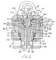
- Fig. 2 is a vertical sectioned view of the rotator
- Fig. 3 is a sectioned view of the rotator taken along the line III-III in Fig. 2
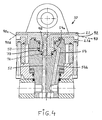
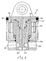
- Figs. 4 and 5 show two further embodiments of the invention.
- a working appliance in the form of a so-called single grip harvesting unit 1 which is suspended from the tip 2 of a machine-carried working arm/crane arm 3 through the medium of a rotator 10.
- the rotator 10 is suspended from a pivot means 4, which allows the appliance 1 to swing via the tip of the working arm.
- the rotator 10 enables the appliance 1 to rotate relative to the tip 2 of the working arm.
- a pair of hydraulic hoses 5 function to supply the rotor 10 with the requisite hydraulic oil
- a number of hydraulic hoses 6 function to supply the appliance 1 with requisite hydraulic oil.
- the hoses 5,6 are connected to a vehicle-carried source of hydraulic oil.
- the rotator 10 comprises a stator 20, which includes an upper stator wall 21, a stator ring 22, and a lower stator wall 23.
- the stator walls 21,23 and the stator ring 22 are held together by a number of screws 24.
- the upper stator wall 21 includes two attachment lugs 25 for coupling the rotator to the working arm 3.
- a rotor 30 is mounted within the stator 20.
- the rotor 30 includes a shaft 31 and is via two radial bearings 32a,32b and via an axial bearing 33 rotatable relative to the stator 20.
- the illustrated rotator 10 is of the so-called wing type, meaning that spring-biased wings 34 on the rotor 30 together with the inner surface 26 of the stator and the outer surface 35 of the rotor define the working chambers 36,37 required for rotational operation of the rotator.
- the rotator is able to rotate through several revolutions and its direction of rotation is reversible.
- Pressure medium is supplied to the rotator through hoses 5 connected to connection points 27a,27b which communicate with the working chambers 36,37 of the rotator through the medium of a number of channels. Although only two channels 28,29 are shown in Fig. 3 , it will be understood that further channels are provided for the working chambers.
- the rotator has an upper seal 40 and two lower seals 41,42.
- a clamping ring 100 is non-rotatably mounted on the lower end 38 of the rotor shaft 31, said clamping ring 100 supporting the working appliance 1, so that rotational movement of the rotator will be transferred to said appliance.
- the inventive rotator includes a rotor 30, which has at its upper end a swivel device 50 and pressure medium channels connecting therewith.
- the upper end of the rotor shaft 31 has a circular recess 51, which forms part of the swivel device.
- the rotor shaft 31 has a first axial channel 52 located in the vicinity of the rotor centre line 53, and a second channel 54 which connects generally radially, or at least partially radially, with the upper recess 51 of the rotor and then detours to a generally axial direction through the rotor shaft 31, as illustrated in Fig. 2 .
- the channel 54 thus has a radial portion 54a and an axial portion 54b.
- the upper stator wall 21 has a downwardly and outwardly protruding central portion 60 which is adapted to fit into the rotor recess 51 essentially with a so-called shape fit.
- the portion 60 forms a part of the swivel device 50.
- the central portion 60 is circular and has a circumferentially extending ring groove 61, which communicates with the channel 54 of the rotor shaft 31.
- a communication channel 62 for pressure medium is provided in the upper state wall 21 and communicates with the ring groove 61. There is thus obtained permanent communication between the channel 62 and the channel 54, regardless of the rotational position of the rotor 30 relative to the stator 20.
- a further pressure medium communication channel 63 is provided in the upper stator wall 21, said channel 63 communicating with a cavity 70 between the downwardly and outwardly projecting portion 60 of the upper stator wall 21 and a bottom surface 71 of the recess 51 in the rotor 30. There is thus obtained constant communication between the channel 63 and the channel 52, regardless of the rotational position of the rotor 30 relative to the stator 20.
- a number of seals 72-74 are disposed between the outwardly protruding portion 60 and the rotor recess 51, to prevent leakage of pressure medium.
- connection points 27a,27b are situated on the top surface 21a of the upper stator wall 21.
- the connection points 76 and 77 of respective channels 62 and 63 are also situated on the top surface 21a of said wall 21.
- the channel 52 in the rotor 30 has an axial connection point 80 in the lower end 38 of the rotor shaft and also a radial connection point 81 via the clamping ring 100, wherein alternative connection points that are not used are plugged.
- the channel 54 in the rotor 30 has an axial connection point 82 in the lower end 38 of the rotor shaft and a radial connection point 83 via the clamping ring 100, wherein alternative connection points that are not used are plugged.
- this embodiment enables all pressure medium supply hoses to be connected to the top surface 21a of the upper stator wall, wherewith the rotator 10 is supplied with pressure medium via the connection points 27a,27b, and the working appliance 1 is supplied with its pressure medium via the connection points 76,77, at the same time as hose communication 7 is, of course, arranged between, e.g., the connection points 80,82 or the connection points 81,83 and the working appliance 1.
- This embodiment thus provides many beneficial hose orientation options.
- connection points 90a,90b for rotator drive medium and connection points 92,93 for working appliance drive medium are provided on the side surface 21b of the stator wall.
- the channel configuration in the upper stator wall 21 has, of course, been adapted to the placement of the connection points.
- the channel configuration of the upper stator wall 21 is such as to enable the rotator 10 to be supplied with pressure medium either via the connection points 80,82 in the rotor 30 or via the connection points 81,83 in the rotor-carried clamping ring 100.
- Those connection points that are not used at that particular time are, of course, plugged.
- the hose connections are on the rotor 30 or on the clamping ring 100, which both accompany the twisting or rotating movement of the appliance 1. This simplifies orientation of the hoses in the case of construction variations in which the rotator 10 is supplied with pressure medium via the working appliance 1, which therewith is supplied with pressure medium via hoses 8, for instance.
- end plugs 95 are provided in the channels 96,97 in the upper stator wall 21.
- the presence of the partially radial channel portion 54a in the rotor 30 means that no additional axial force or thrust will occur on the rotator 10 as a result of the supply of pressure medium via the channel 54, which is highly beneficial from the aspect of stress.
- the medium-conducting channel 54 will preferably be used so as to be pressure-activated when the working appliance 1 is load bearing.
- the swivel device 50 includes a shoulder part 98 that has a seal 72,73 on both sides thereof.
- the channel system 63,52 can be replaced by a further channel system similar to the channel 62,54 and a further ring groove similar to the ring groove 61.
- a significant advantage provided by the present invention is that the swivel coupling/swivel device 50 is arranged within the rotor/the rotor shaft such as to make possible many different pressure medium connection alternatives, whilst eliminating undesirable thrust additions.
- the configuration of the pressure medium channels may be varied according to requirements and desires within the scope of the inventive concept.
- the ring groove or ring grooves may also be provided in the end-recess of the rotor shaft.
- the channels 63 and 52 may also be positioned to coincide with the rotor centre line 53.
- the structural design of the channel 54 and its extension may, of course, be varied, provided that the transition between the channels 62 and 54 will allow the continuous transfer of pressure medium.
Landscapes
- Engineering & Computer Science (AREA)
- Mechanical Engineering (AREA)
- Mining & Mineral Resources (AREA)
- Civil Engineering (AREA)
- General Engineering & Computer Science (AREA)
- Structural Engineering (AREA)
- Joints Allowing Movement (AREA)
- Pivots And Pivotal Connections (AREA)
- Soil Working Implements (AREA)
- Massaging Devices (AREA)
- Specific Conveyance Elements (AREA)
- Forklifts And Lifting Vehicles (AREA)
Claims (10)
- Dreheinrichtung, im Besonderen für arm-gestützte Arbeitseinrichtungen, wobei die Dreheinrichtung (10) einen Stator (20), einen Rotor (30) mit einer Welle (31) und eine Drehkupplung/Drehvorrichtung (50) zur Übertragung des Arbeitsdrucksmittels zwischen dem Stator (20) und dem Rotor (30) im Einsatz aufweist, und wobei die Drehvorrichtung (50) in dem Rotor (30) angeordnet ist,
dadurch gekennzeichnet, dass
die Rotorwelle (31) wenigstens einen Mittelübertragungskanal (54) enthält, der wenigstens teilweise radial mit einer Aussparung (51) in der Rotorwelle (31) verbunden ist. - Dreheinrichtung gemäß Anspruch 1, dadurch gekennzeichnet, dass der Stator (20) ein nach außen hervorstehendes Teil (60) trägt, das einen Teil der Drehvorrichtung (50) bildet.
- Dreheinrichtung gemäß Anspruch 1 oder 2, dadurch gekennzeichnet, dass die Rotorwelle (31) eine Aussparung (51) enthält, die einen Teil der Drehvorrichtung (50) bildet.
- Dreheinrichtung gemäß einem der Ansprüche 1 bis 3, dadurch gekennzeichnet, dass die Rotorwelle (31) einen Kanal (52) enthält, der allgemein axial mit der Aussparung (51) in der Rotorwelle (31) verbunden ist.
- Dreheinrichtung gemäß einem der Ansprüche 2 bis 4, dadurch gekennzeichnet, dass das nach außen hervorstehende Teil (60) des Stators (20) und/oder der Rotorwelle (31) wenigstens eine Ringnut (61) zum Zusammenwirken mit einem (54) der Rotorwellenkanäle enthält.
- Drehvorrichtung gemäß einem der Ansprüche 1 bis 5, dadurch gekennzeichnet, dass die Rotorwelle (31) einen Kanal (54) enthält, der ein allgemein axiales Teil (54a) und ein im Allgemeinen axiales Teil (54b) aufweist.
- Drehvorrichtung gemäß einem der Ansprüche 1 bis 6, dadurch gekennzeichnet, dass die Rotorwelle (31) einen allgemein axialen Kanal (52) enthält, der sich von der Bodenfläche (71) der Aussparung (51) in der Rotorwelle (31) zu einem unteren Ende (38) der Rotorwelle erstreckt.
- Dreheinrichtung gemäß einem der Ansprüche 4 bis 7, dadurch gekennzeichnet, dass die Rotorwellenkanäle (52, 54) sich zu den Verbindungspunkten (80, 82) in einer unteren Endseite (38) der Rotorwelle (31) und/oder zu radialen Verbindungspunkten (81, 83) in einem Klemmring (100) auf der Rotorwelle erstrecken.
- Dreheinrichtung gemäß einem der Ansprüche 2 bis 8, gekennzeichnet durch eine Lücke oder einen Freiraum (70) zwischen einer Bodenfläche des nach unten hervorstehenden Teils (60) des Stators (20) und einer Bodenfläche (71) der Rotorwellenaussparung (51).
- Dreheinrichtung gemäß einem der Ansprüche 1 bis 9, dadurch gekennzeichnet, dass eine obere Statorwand (21) Verbindungspunkte (76, 77) und/oder Kanäle (62, 63) enthält, die mit den Kanälen (52, 54) der Rotorwelle (31) in Verbindung stehen.
Applications Claiming Priority (3)
| Application Number | Priority Date | Filing Date | Title |
|---|---|---|---|
| SE0200994A SE525043C2 (sv) | 2002-04-02 | 2002-04-02 | Anordning vid en rotator |
| SE0200994 | 2002-04-02 | ||
| PCT/SE2003/000522 WO2003082725A1 (en) | 2002-04-02 | 2003-04-01 | Arrangement at a rotator |
Publications (2)
| Publication Number | Publication Date |
|---|---|
| EP1494952A1 EP1494952A1 (de) | 2005-01-12 |
| EP1494952B1 true EP1494952B1 (de) | 2009-01-07 |
Family
ID=20287460
Family Applications (1)
| Application Number | Title | Priority Date | Filing Date |
|---|---|---|---|
| EP03745501A Expired - Lifetime EP1494952B1 (de) | 2002-04-02 | 2003-04-01 | Anordnung an einer drehvorrichtung |
Country Status (7)
| Country | Link |
|---|---|
| EP (1) | EP1494952B1 (de) |
| AT (1) | ATE420053T1 (de) |
| AU (1) | AU2003225447A1 (de) |
| CA (1) | CA2480885C (de) |
| DE (1) | DE60325712D1 (de) |
| SE (1) | SE525043C2 (de) |
| WO (1) | WO2003082725A1 (de) |
Families Citing this family (14)
| Publication number | Priority date | Publication date | Assignee | Title |
|---|---|---|---|---|
| EP2201209B1 (de) | 2007-08-31 | 2013-09-18 | LaValley Industries, LLC. | Greifanbauteil für den einsatz mit bohrrohren |
| US8567836B2 (en) | 2007-08-31 | 2013-10-29 | Lavalley Industries, Llc | Gripping assembly and gripping members for a grapple attachment |
| ATE513125T1 (de) | 2008-08-29 | 2011-07-15 | Baltrotors Sia | Kolbendrehmaschine |
| IT1391620B1 (it) * | 2008-11-05 | 2012-01-11 | Soilmec Spa | Dispositivo di movimentazione di un utensile di scavo nel terreno verticalmente sospeso. |
| WO2012112863A2 (en) | 2011-02-17 | 2012-08-23 | Lavalley Industries, Llc | Position adjustable grapple attachment |
| SE538285C2 (sv) * | 2012-05-18 | 2016-04-26 | Turnset Ab | Kring en vridningsaxel vridbart arrangemang |
| BR112015001676B1 (pt) | 2012-07-27 | 2022-02-08 | Lavalley Industries, Llc | Alojamento de braço de sujeição para acessório de acoplamento |
| SE539110C2 (sv) * | 2013-04-10 | 2017-04-11 | Indexator Rotator Sys Ab | Svivelanordning vid en rotator |
| WO2015007943A1 (en) * | 2013-07-19 | 2015-01-22 | Timaco Oy | Pressure medium operated actuator |
| WO2015155627A1 (en) * | 2014-04-10 | 2015-10-15 | Ala Officine S.P.A. | Multipath fluidic rotary distributor |
| US8973244B2 (en) | 2014-04-17 | 2015-03-10 | Lavalley Industries, Llc | Pipe processing tool with pipe deformation members |
| SE538568C2 (en) * | 2014-12-19 | 2016-09-20 | Indexator Rotator Sys Ab | Rotator for a jib-carried tool |
| SE1850692A1 (en) * | 2018-06-08 | 2019-12-09 | Indexator Rotator Sys Ab | Hydraulic rotator aparatus |
| BR112022020057A2 (pt) | 2020-04-08 | 2022-11-22 | Indexator Rotator Sys Ab | Rotador para uma ferramenta |
Family Cites Families (4)
| Publication number | Priority date | Publication date | Assignee | Title |
|---|---|---|---|---|
| FR2239603A1 (en) * | 1973-07-31 | 1975-02-28 | Thumm Heinz | Hydraulic motor for rotating grab scoop on excavator arm - stator and rotor connected to arm and scoop respectively |
| SE410214B (sv) * | 1978-04-11 | 1979-10-01 | Bergs Smide Ab K A | Kullagerlekare |
| DE3146695A1 (de) * | 1981-11-25 | 1983-07-07 | Heinz Thumm Ölhydraulische Antriebe GmbH, 7012 Fellbach | Hydromotor, insbesondere fuer greiferdreheinrichtung an baggern oder kraenen |
| SE457436B (sv) * | 1987-12-28 | 1988-12-27 | Oesa Ab | Rotator foer kranburna arbetsredskap |
-
2002
- 2002-04-02 SE SE0200994A patent/SE525043C2/sv not_active IP Right Cessation
-
2003
- 2003-04-01 CA CA2480885A patent/CA2480885C/en not_active Expired - Fee Related
- 2003-04-01 DE DE60325712T patent/DE60325712D1/de not_active Expired - Lifetime
- 2003-04-01 AT AT03745501T patent/ATE420053T1/de not_active IP Right Cessation
- 2003-04-01 EP EP03745501A patent/EP1494952B1/de not_active Expired - Lifetime
- 2003-04-01 AU AU2003225447A patent/AU2003225447A1/en not_active Abandoned
- 2003-04-01 WO PCT/SE2003/000522 patent/WO2003082725A1/en not_active Ceased
Also Published As
| Publication number | Publication date |
|---|---|
| DE60325712D1 (de) | 2009-02-26 |
| WO2003082725A1 (en) | 2003-10-09 |
| CA2480885C (en) | 2011-01-11 |
| ATE420053T1 (de) | 2009-01-15 |
| AU2003225447A1 (en) | 2003-10-13 |
| SE0200994L (sv) | 2003-10-03 |
| CA2480885A1 (en) | 2003-10-09 |
| EP1494952A1 (de) | 2005-01-12 |
| SE0200994D0 (sv) | 2002-04-02 |
| SE525043C2 (sv) | 2004-11-16 |
Similar Documents
| Publication | Publication Date | Title |
|---|---|---|
| EP1494952B1 (de) | Anordnung an einer drehvorrichtung | |
| US7066076B2 (en) | Motor-driven, boom-mounted rotary coupling | |
| US8074681B2 (en) | Swivel and rotator mechanism for fluid controlled machines | |
| CN1650118B (zh) | 减速器 | |
| KR102558578B1 (ko) | 굴삭기용 틸트 로테이터장치 | |
| EP0424378B1 (de) | Drehvorrichtung für kranmontierte werkzeuge, insbesondere solche für bearbeitung von bäumen | |
| RU2738981C2 (ru) | Конструкция ротационного устройства и соответствующее ротационное устройство, и лесозаготовительная машина | |
| EP1476388B1 (de) | Rotator | |
| US4009643A (en) | Hydraulic motor for rotating the bucket of an excavating machine | |
| CA1045399A (en) | Pump motor combination for hydraulic implement | |
| ATE183793T1 (de) | Drehvorrichtung für baggergreifer | |
| CA2594051C (en) | A cutter head for an excavator machine | |
| EP3850247B1 (de) | Planetengetriebe und fahrzeug oder stationäre einheit mit solch einem planetengetriebe | |
| US6123518A (en) | Integral shaft coupling for a flexible driveplate in a pump drivetrain | |
| CN118187851A (zh) | 一种悬切破岩装置及掘进机 | |
| EP4132876B1 (de) | Rotator für ein werkzeug | |
| KR100625606B1 (ko) | 유체커플링 | |
| RU224887U1 (ru) | Гидравлическое вращательное устройство | |
| EP3640514B1 (de) | Hydraulische verbindung und hydraulische auslegerkrananordnung mit einer hydraulischen verbindung | |
| CN101817482A (zh) | 一种复合芯液压中央回转体 | |
| RU225741U1 (ru) | Гидравлическое вращательное устройство | |
| CN215486923U (zh) | 一种液压驱动器 | |
| CN111691480A (zh) | 地下连续墙施工设备 | |
| CN209293957U (zh) | 一种液压马达用缸体组件 | |
| CN218207452U (zh) | 一种新型卷筒式联轴器 |
Legal Events
| Date | Code | Title | Description |
|---|---|---|---|
| PUAI | Public reference made under article 153(3) epc to a published international application that has entered the european phase |
Free format text: ORIGINAL CODE: 0009012 |
|
| 17P | Request for examination filed |
Effective date: 20041019 |
|
| AK | Designated contracting states |
Kind code of ref document: A1 Designated state(s): AT BE BG CH CY CZ DE DK EE ES FI FR GB GR HU IE IT LI LU MC NL PT RO SE SI SK TR |
|
| AX | Request for extension of the european patent |
Extension state: AL LT LV MK |
|
| RIN1 | Information on inventor provided before grant (corrected) |
Inventor name: HARR, JOAKIM |
|
| GRAP | Despatch of communication of intention to grant a patent |
Free format text: ORIGINAL CODE: EPIDOSNIGR1 |
|
| GRAS | Grant fee paid |
Free format text: ORIGINAL CODE: EPIDOSNIGR3 |
|
| GRAA | (expected) grant |
Free format text: ORIGINAL CODE: 0009210 |
|
| AK | Designated contracting states |
Kind code of ref document: B1 Designated state(s): AT BE BG CH CY CZ DE DK EE ES FI FR GB GR HU IE IT LI LU MC NL PT RO SE SI SK TR |
|
| AX | Request for extension of the european patent |
Extension state: LV |
|
| REG | Reference to a national code |
Ref country code: GB Ref legal event code: FG4D |
|
| REG | Reference to a national code |
Ref country code: CH Ref legal event code: EP |
|
| REG | Reference to a national code |
Ref country code: IE Ref legal event code: FG4D |
|
| REF | Corresponds to: |
Ref document number: 60325712 Country of ref document: DE Date of ref document: 20090226 Kind code of ref document: P |
|
| PG25 | Lapsed in a contracting state [announced via postgrant information from national office to epo] |
Ref country code: SI Free format text: LAPSE BECAUSE OF FAILURE TO SUBMIT A TRANSLATION OF THE DESCRIPTION OR TO PAY THE FEE WITHIN THE PRESCRIBED TIME-LIMIT Effective date: 20090107 Ref country code: NL Free format text: LAPSE BECAUSE OF FAILURE TO SUBMIT A TRANSLATION OF THE DESCRIPTION OR TO PAY THE FEE WITHIN THE PRESCRIBED TIME-LIMIT Effective date: 20090107 |
|
| NLV1 | Nl: lapsed or annulled due to failure to fulfill the requirements of art. 29p and 29m of the patents act | ||
| PG25 | Lapsed in a contracting state [announced via postgrant information from national office to epo] |
Ref country code: ES Free format text: LAPSE BECAUSE OF FAILURE TO SUBMIT A TRANSLATION OF THE DESCRIPTION OR TO PAY THE FEE WITHIN THE PRESCRIBED TIME-LIMIT Effective date: 20090418 |
|
| PG25 | Lapsed in a contracting state [announced via postgrant information from national office to epo] |
Ref country code: SE Free format text: LAPSE BECAUSE OF FAILURE TO SUBMIT A TRANSLATION OF THE DESCRIPTION OR TO PAY THE FEE WITHIN THE PRESCRIBED TIME-LIMIT Effective date: 20090407 Ref country code: PT Free format text: LAPSE BECAUSE OF FAILURE TO SUBMIT A TRANSLATION OF THE DESCRIPTION OR TO PAY THE FEE WITHIN THE PRESCRIBED TIME-LIMIT Effective date: 20090608 Ref country code: AT Free format text: LAPSE BECAUSE OF FAILURE TO SUBMIT A TRANSLATION OF THE DESCRIPTION OR TO PAY THE FEE WITHIN THE PRESCRIBED TIME-LIMIT Effective date: 20090107 |
|
| PG25 | Lapsed in a contracting state [announced via postgrant information from national office to epo] |
Ref country code: BE Free format text: LAPSE BECAUSE OF FAILURE TO SUBMIT A TRANSLATION OF THE DESCRIPTION OR TO PAY THE FEE WITHIN THE PRESCRIBED TIME-LIMIT Effective date: 20090107 |
|
| PG25 | Lapsed in a contracting state [announced via postgrant information from national office to epo] |
Ref country code: DK Free format text: LAPSE BECAUSE OF FAILURE TO SUBMIT A TRANSLATION OF THE DESCRIPTION OR TO PAY THE FEE WITHIN THE PRESCRIBED TIME-LIMIT Effective date: 20090107 Ref country code: CZ Free format text: LAPSE BECAUSE OF FAILURE TO SUBMIT A TRANSLATION OF THE DESCRIPTION OR TO PAY THE FEE WITHIN THE PRESCRIBED TIME-LIMIT Effective date: 20090107 Ref country code: EE Free format text: LAPSE BECAUSE OF FAILURE TO SUBMIT A TRANSLATION OF THE DESCRIPTION OR TO PAY THE FEE WITHIN THE PRESCRIBED TIME-LIMIT Effective date: 20090107 |
|
| PLBE | No opposition filed within time limit |
Free format text: ORIGINAL CODE: 0009261 |
|
| STAA | Information on the status of an ep patent application or granted ep patent |
Free format text: STATUS: NO OPPOSITION FILED WITHIN TIME LIMIT |
|
| PG25 | Lapsed in a contracting state [announced via postgrant information from national office to epo] |
Ref country code: SK Free format text: LAPSE BECAUSE OF FAILURE TO SUBMIT A TRANSLATION OF THE DESCRIPTION OR TO PAY THE FEE WITHIN THE PRESCRIBED TIME-LIMIT Effective date: 20090107 Ref country code: RO Free format text: LAPSE BECAUSE OF FAILURE TO SUBMIT A TRANSLATION OF THE DESCRIPTION OR TO PAY THE FEE WITHIN THE PRESCRIBED TIME-LIMIT Effective date: 20090107 |
|
| REG | Reference to a national code |
Ref country code: CH Ref legal event code: PL |
|
| 26N | No opposition filed |
Effective date: 20091008 |
|
| GBPC | Gb: european patent ceased through non-payment of renewal fee |
Effective date: 20090407 |
|
| PG25 | Lapsed in a contracting state [announced via postgrant information from national office to epo] |
Ref country code: LI Free format text: LAPSE BECAUSE OF NON-PAYMENT OF DUE FEES Effective date: 20090430 Ref country code: BG Free format text: LAPSE BECAUSE OF FAILURE TO SUBMIT A TRANSLATION OF THE DESCRIPTION OR TO PAY THE FEE WITHIN THE PRESCRIBED TIME-LIMIT Effective date: 20090407 Ref country code: CH Free format text: LAPSE BECAUSE OF NON-PAYMENT OF DUE FEES Effective date: 20090430 |
|
| REG | Reference to a national code |
Ref country code: IE Ref legal event code: MM4A |
|
| PG25 | Lapsed in a contracting state [announced via postgrant information from national office to epo] |
Ref country code: MC Free format text: LAPSE BECAUSE OF NON-PAYMENT OF DUE FEES Effective date: 20090430 Ref country code: IE Free format text: LAPSE BECAUSE OF NON-PAYMENT OF DUE FEES Effective date: 20090401 Ref country code: GB Free format text: LAPSE BECAUSE OF NON-PAYMENT OF DUE FEES Effective date: 20090407 |
|
| PG25 | Lapsed in a contracting state [announced via postgrant information from national office to epo] |
Ref country code: GR Free format text: LAPSE BECAUSE OF FAILURE TO SUBMIT A TRANSLATION OF THE DESCRIPTION OR TO PAY THE FEE WITHIN THE PRESCRIBED TIME-LIMIT Effective date: 20090408 |
|
| PG25 | Lapsed in a contracting state [announced via postgrant information from national office to epo] |
Ref country code: LU Free format text: LAPSE BECAUSE OF NON-PAYMENT OF DUE FEES Effective date: 20090401 |
|
| PG25 | Lapsed in a contracting state [announced via postgrant information from national office to epo] |
Ref country code: HU Free format text: LAPSE BECAUSE OF FAILURE TO SUBMIT A TRANSLATION OF THE DESCRIPTION OR TO PAY THE FEE WITHIN THE PRESCRIBED TIME-LIMIT Effective date: 20090708 |
|
| PG25 | Lapsed in a contracting state [announced via postgrant information from national office to epo] |
Ref country code: TR Free format text: LAPSE BECAUSE OF FAILURE TO SUBMIT A TRANSLATION OF THE DESCRIPTION OR TO PAY THE FEE WITHIN THE PRESCRIBED TIME-LIMIT Effective date: 20090107 |
|
| PG25 | Lapsed in a contracting state [announced via postgrant information from national office to epo] |
Ref country code: CY Free format text: LAPSE BECAUSE OF FAILURE TO SUBMIT A TRANSLATION OF THE DESCRIPTION OR TO PAY THE FEE WITHIN THE PRESCRIBED TIME-LIMIT Effective date: 20090107 |
|
| REG | Reference to a national code |
Ref country code: DE Ref legal event code: R082 Ref document number: 60325712 Country of ref document: DE Representative=s name: MITSCHERLICH, PATENT- UND RECHTSANWAELTE, PART, DE |
|
| REG | Reference to a national code |
Ref country code: FR Ref legal event code: TP Owner name: INDEXATOR GROUP AB, SE Effective date: 20131223 |
|
| REG | Reference to a national code |
Ref country code: DE Ref legal event code: R082 Ref document number: 60325712 Country of ref document: DE Representative=s name: MITSCHERLICH, PATENT- UND RECHTSANWAELTE, PART, DE Effective date: 20131210 Ref country code: DE Ref legal event code: R081 Ref document number: 60325712 Country of ref document: DE Owner name: INDEXATOR GROUP AB, SE Free format text: FORMER OWNER: INDEXATOR AB, VINDELN, SE Effective date: 20131210 Ref country code: DE Ref legal event code: R082 Ref document number: 60325712 Country of ref document: DE Representative=s name: MITSCHERLICH, PATENT- UND RECHTSANWAELTE PARTM, DE Effective date: 20131210 Ref country code: DE Ref legal event code: R081 Ref document number: 60325712 Country of ref document: DE Owner name: INDEXATOR ROTATOR SYSTEMS AB, SE Free format text: FORMER OWNER: INDEXATOR AB, VINDELN, SE Effective date: 20131210 |
|
| REG | Reference to a national code |
Ref country code: FR Ref legal event code: RM Effective date: 20140314 |
|
| PGFP | Annual fee paid to national office [announced via postgrant information from national office to epo] |
Ref country code: FR Payment date: 20140430 Year of fee payment: 12 Ref country code: IT Payment date: 20140424 Year of fee payment: 12 |
|
| REG | Reference to a national code |
Ref country code: DE Ref legal event code: R082 Ref document number: 60325712 Country of ref document: DE Representative=s name: MITSCHERLICH, PATENT- UND RECHTSANWAELTE PARTM, DE |
|
| REG | Reference to a national code |
Ref country code: DE Ref legal event code: R081 Ref document number: 60325712 Country of ref document: DE Owner name: INDEXATOR ROTATOR SYSTEMS AB, SE Free format text: FORMER OWNER: INDEXATOR GROUP AB, VINDELN, SE Effective date: 20150212 Ref country code: DE Ref legal event code: R082 Ref document number: 60325712 Country of ref document: DE Representative=s name: MITSCHERLICH, PATENT- UND RECHTSANWAELTE PARTM, DE Effective date: 20150212 |
|
| PG25 | Lapsed in a contracting state [announced via postgrant information from national office to epo] |
Ref country code: IT Free format text: LAPSE BECAUSE OF NON-PAYMENT OF DUE FEES Effective date: 20150401 |
|
| REG | Reference to a national code |
Ref country code: FR Ref legal event code: ST Effective date: 20151231 |
|
| PG25 | Lapsed in a contracting state [announced via postgrant information from national office to epo] |
Ref country code: FR Free format text: LAPSE BECAUSE OF NON-PAYMENT OF DUE FEES Effective date: 20150430 |
|
| PGFP | Annual fee paid to national office [announced via postgrant information from national office to epo] |
Ref country code: DE Payment date: 20180418 Year of fee payment: 16 Ref country code: FI Payment date: 20180418 Year of fee payment: 16 |
|
| REG | Reference to a national code |
Ref country code: DE Ref legal event code: R119 Ref document number: 60325712 Country of ref document: DE |
|
| PG25 | Lapsed in a contracting state [announced via postgrant information from national office to epo] |
Ref country code: FI Free format text: LAPSE BECAUSE OF NON-PAYMENT OF DUE FEES Effective date: 20190401 Ref country code: DE Free format text: LAPSE BECAUSE OF NON-PAYMENT OF DUE FEES Effective date: 20191101 |