EP1494970B1 - Vorrichtung zur aufzucht von vieh - Google Patents
Vorrichtung zur aufzucht von vieh Download PDFInfo
- Publication number
- EP1494970B1 EP1494970B1 EP02718703A EP02718703A EP1494970B1 EP 1494970 B1 EP1494970 B1 EP 1494970B1 EP 02718703 A EP02718703 A EP 02718703A EP 02718703 A EP02718703 A EP 02718703A EP 1494970 B1 EP1494970 B1 EP 1494970B1
- Authority
- EP
- European Patent Office
- Prior art keywords
- pipe
- dissolved air
- treatment tank
- air flotation
- disposed
- Prior art date
- Legal status (The legal status is an assumption and is not a legal conclusion. Google has not performed a legal analysis and makes no representation as to the accuracy of the status listed.)
- Expired - Lifetime
Links
- 238000011282 treatment Methods 0.000 claims abstract description 178
- 238000009300 dissolved air flotation Methods 0.000 claims abstract description 104
- 239000010802 sludge Substances 0.000 claims abstract description 100
- 238000005273 aeration Methods 0.000 claims abstract description 98
- 239000007788 liquid Substances 0.000 claims abstract description 92
- 230000029142 excretion Effects 0.000 claims abstract description 86
- 238000005188 flotation Methods 0.000 claims abstract description 35
- 238000001914 filtration Methods 0.000 claims abstract description 14
- 239000004576 sand Substances 0.000 claims abstract description 9
- OKTJSMMVPCPJKN-UHFFFAOYSA-N Carbon Chemical compound [C] OKTJSMMVPCPJKN-UHFFFAOYSA-N 0.000 claims abstract description 8
- 229910052799 carbon Inorganic materials 0.000 claims abstract description 8
- 239000013530 defoamer Substances 0.000 claims description 71
- 238000007599 discharging Methods 0.000 claims description 31
- 239000006260 foam Substances 0.000 claims description 28
- XLYOFNOQVPJJNP-UHFFFAOYSA-N water Substances O XLYOFNOQVPJJNP-UHFFFAOYSA-N 0.000 claims description 28
- 230000001939 inductive effect Effects 0.000 claims description 15
- 239000007787 solid Substances 0.000 claims description 6
- 239000007789 gas Substances 0.000 description 25
- 238000000034 method Methods 0.000 description 19
- 244000144972 livestock Species 0.000 description 13
- VNWKTOKETHGBQD-UHFFFAOYSA-N methane Chemical compound C VNWKTOKETHGBQD-UHFFFAOYSA-N 0.000 description 6
- QVGXLLKOCUKJST-UHFFFAOYSA-N atomic oxygen Chemical compound [O] QVGXLLKOCUKJST-UHFFFAOYSA-N 0.000 description 5
- 239000000463 material Substances 0.000 description 5
- 244000005700 microbiome Species 0.000 description 5
- 229910052760 oxygen Inorganic materials 0.000 description 5
- 239000001301 oxygen Substances 0.000 description 5
- 238000005507 spraying Methods 0.000 description 5
- 239000002361 compost Substances 0.000 description 3
- 239000003337 fertilizer Substances 0.000 description 3
- 230000008569 process Effects 0.000 description 3
- 230000009467 reduction Effects 0.000 description 3
- 210000002700 urine Anatomy 0.000 description 3
- 239000002351 wastewater Substances 0.000 description 3
- QGZKDVFQNNGYKY-UHFFFAOYSA-N Ammonia Chemical compound N QGZKDVFQNNGYKY-UHFFFAOYSA-N 0.000 description 2
- 230000006872 improvement Effects 0.000 description 2
- 239000011368 organic material Substances 0.000 description 2
- 239000010865 sewage Substances 0.000 description 2
- 239000002699 waste material Substances 0.000 description 2
- 238000004065 wastewater treatment Methods 0.000 description 2
- 102000009027 Albumins Human genes 0.000 description 1
- 108010088751 Albumins Proteins 0.000 description 1
- OAICVXFJPJFONN-UHFFFAOYSA-N Phosphorus Chemical compound [P] OAICVXFJPJFONN-UHFFFAOYSA-N 0.000 description 1
- 229910021529 ammonia Inorganic materials 0.000 description 1
- 244000052616 bacterial pathogen Species 0.000 description 1
- 239000003795 chemical substances by application Substances 0.000 description 1
- 230000018044 dehydration Effects 0.000 description 1
- 238000006297 dehydration reaction Methods 0.000 description 1
- 230000008021 deposition Effects 0.000 description 1
- 210000003608 fece Anatomy 0.000 description 1
- 238000000855 fermentation Methods 0.000 description 1
- 230000004151 fermentation Effects 0.000 description 1
- 230000036541 health Effects 0.000 description 1
- 229910001385 heavy metal Inorganic materials 0.000 description 1
- 239000012535 impurity Substances 0.000 description 1
- 229910010272 inorganic material Inorganic materials 0.000 description 1
- 239000011147 inorganic material Substances 0.000 description 1
- 201000010260 leiomyoma Diseases 0.000 description 1
- 239000010871 livestock manure Substances 0.000 description 1
- 238000012423 maintenance Methods 0.000 description 1
- 238000002156 mixing Methods 0.000 description 1
- 238000007254 oxidation reaction Methods 0.000 description 1
- 239000002245 particle Substances 0.000 description 1
- 229910052698 phosphorus Inorganic materials 0.000 description 1
- 239000011574 phosphorus Substances 0.000 description 1
- 238000002360 preparation method Methods 0.000 description 1
- 230000001105 regulatory effect Effects 0.000 description 1
- 238000007789 sealing Methods 0.000 description 1
- 239000002689 soil Substances 0.000 description 1
- 230000000087 stabilizing effect Effects 0.000 description 1
Images


Classifications
-
- B—PERFORMING OPERATIONS; TRANSPORTING
- B01—PHYSICAL OR CHEMICAL PROCESSES OR APPARATUS IN GENERAL
- B01D—SEPARATION
- B01D21/00—Separation of suspended solid particles from liquids by sedimentation
- B01D21/0012—Settling tanks making use of filters, e.g. by floating layers of particulate material
-
- C—CHEMISTRY; METALLURGY
- C02—TREATMENT OF WATER, WASTE WATER, SEWAGE, OR SLUDGE
- C02F—TREATMENT OF WATER, WASTE WATER, SEWAGE, OR SLUDGE
- C02F1/00—Treatment of water, waste water, or sewage
- C02F1/24—Treatment of water, waste water, or sewage by flotation
-
- B—PERFORMING OPERATIONS; TRANSPORTING
- B01—PHYSICAL OR CHEMICAL PROCESSES OR APPARATUS IN GENERAL
- B01D—SEPARATION
- B01D19/00—Degasification of liquids
- B01D19/02—Foam dispersion or prevention
-
- B—PERFORMING OPERATIONS; TRANSPORTING
- B01—PHYSICAL OR CHEMICAL PROCESSES OR APPARATUS IN GENERAL
- B01D—SEPARATION
- B01D21/00—Separation of suspended solid particles from liquids by sedimentation
- B01D21/0003—Making of sedimentation devices, structural details thereof, e.g. prefabricated parts
-
- B—PERFORMING OPERATIONS; TRANSPORTING
- B01—PHYSICAL OR CHEMICAL PROCESSES OR APPARATUS IN GENERAL
- B01D—SEPARATION
- B01D21/00—Separation of suspended solid particles from liquids by sedimentation
- B01D21/0039—Settling tanks provided with contact surfaces, e.g. baffles, particles
- B01D21/0069—Making of contact surfaces, structural details, materials therefor
- B01D21/0075—Contact surfaces having surface features
-
- B—PERFORMING OPERATIONS; TRANSPORTING
- B01—PHYSICAL OR CHEMICAL PROCESSES OR APPARATUS IN GENERAL
- B01D—SEPARATION
- B01D21/00—Separation of suspended solid particles from liquids by sedimentation
- B01D21/24—Feed or discharge mechanisms for settling tanks
- B01D21/2405—Feed mechanisms for settling tanks
-
- B—PERFORMING OPERATIONS; TRANSPORTING
- B01—PHYSICAL OR CHEMICAL PROCESSES OR APPARATUS IN GENERAL
- B01D—SEPARATION
- B01D21/00—Separation of suspended solid particles from liquids by sedimentation
- B01D21/24—Feed or discharge mechanisms for settling tanks
- B01D21/245—Discharge mechanisms for the sediments
- B01D21/2466—Mammoth pumps, e.g. air lift pumps
-
- B—PERFORMING OPERATIONS; TRANSPORTING
- B01—PHYSICAL OR CHEMICAL PROCESSES OR APPARATUS IN GENERAL
- B01D—SEPARATION
- B01D21/00—Separation of suspended solid particles from liquids by sedimentation
- B01D21/28—Mechanical auxiliary equipment for acceleration of sedimentation, e.g. by vibrators or the like
-
- B—PERFORMING OPERATIONS; TRANSPORTING
- B03—SEPARATION OF SOLID MATERIALS USING LIQUIDS OR USING PNEUMATIC TABLES OR JIGS; MAGNETIC OR ELECTROSTATIC SEPARATION OF SOLID MATERIALS FROM SOLID MATERIALS OR FLUIDS; SEPARATION BY HIGH-VOLTAGE ELECTRIC FIELDS
- B03D—FLOTATION; DIFFERENTIAL SEDIMENTATION
- B03D1/00—Flotation
- B03D1/14—Flotation machines
- B03D1/1406—Flotation machines with special arrangement of a plurality of flotation cells, e.g. positioning a flotation cell inside another
-
- B—PERFORMING OPERATIONS; TRANSPORTING
- B03—SEPARATION OF SOLID MATERIALS USING LIQUIDS OR USING PNEUMATIC TABLES OR JIGS; MAGNETIC OR ELECTROSTATIC SEPARATION OF SOLID MATERIALS FROM SOLID MATERIALS OR FLUIDS; SEPARATION BY HIGH-VOLTAGE ELECTRIC FIELDS
- B03D—FLOTATION; DIFFERENTIAL SEDIMENTATION
- B03D1/00—Flotation
- B03D1/14—Flotation machines
- B03D1/1431—Dissolved air flotation machines
-
- B—PERFORMING OPERATIONS; TRANSPORTING
- B03—SEPARATION OF SOLID MATERIALS USING LIQUIDS OR USING PNEUMATIC TABLES OR JIGS; MAGNETIC OR ELECTROSTATIC SEPARATION OF SOLID MATERIALS FROM SOLID MATERIALS OR FLUIDS; SEPARATION BY HIGH-VOLTAGE ELECTRIC FIELDS
- B03D—FLOTATION; DIFFERENTIAL SEDIMENTATION
- B03D1/00—Flotation
- B03D1/14—Flotation machines
- B03D1/1443—Feed or discharge mechanisms for flotation tanks
- B03D1/1462—Discharge mechanisms for the froth
-
- B—PERFORMING OPERATIONS; TRANSPORTING
- B03—SEPARATION OF SOLID MATERIALS USING LIQUIDS OR USING PNEUMATIC TABLES OR JIGS; MAGNETIC OR ELECTROSTATIC SEPARATION OF SOLID MATERIALS FROM SOLID MATERIALS OR FLUIDS; SEPARATION BY HIGH-VOLTAGE ELECTRIC FIELDS
- B03D—FLOTATION; DIFFERENTIAL SEDIMENTATION
- B03D1/00—Flotation
- B03D1/14—Flotation machines
- B03D1/16—Flotation machines with impellers; Subaeration machines
- B03D1/20—Flotation machines with impellers; Subaeration machines with internal air pumps
-
- C—CHEMISTRY; METALLURGY
- C02—TREATMENT OF WATER, WASTE WATER, SEWAGE, OR SLUDGE
- C02F—TREATMENT OF WATER, WASTE WATER, SEWAGE, OR SLUDGE
- C02F1/00—Treatment of water, waste water, or sewage
- C02F1/001—Processes for the treatment of water whereby the filtration technique is of importance
-
- C—CHEMISTRY; METALLURGY
- C02—TREATMENT OF WATER, WASTE WATER, SEWAGE, OR SLUDGE
- C02F—TREATMENT OF WATER, WASTE WATER, SEWAGE, OR SLUDGE
- C02F1/00—Treatment of water, waste water, or sewage
- C02F1/28—Treatment of water, waste water, or sewage by sorption
- C02F1/283—Treatment of water, waste water, or sewage by sorption using coal, charred products, or inorganic mixtures containing them
-
- C—CHEMISTRY; METALLURGY
- C02—TREATMENT OF WATER, WASTE WATER, SEWAGE, OR SLUDGE
- C02F—TREATMENT OF WATER, WASTE WATER, SEWAGE, OR SLUDGE
- C02F1/00—Treatment of water, waste water, or sewage
- C02F1/72—Treatment of water, waste water, or sewage by oxidation
- C02F1/74—Treatment of water, waste water, or sewage by oxidation with air
-
- C—CHEMISTRY; METALLURGY
- C02—TREATMENT OF WATER, WASTE WATER, SEWAGE, OR SLUDGE
- C02F—TREATMENT OF WATER, WASTE WATER, SEWAGE, OR SLUDGE
- C02F11/00—Treatment of sludge; Devices therefor
- C02F11/02—Biological treatment
-
- C—CHEMISTRY; METALLURGY
- C02—TREATMENT OF WATER, WASTE WATER, SEWAGE, OR SLUDGE
- C02F—TREATMENT OF WATER, WASTE WATER, SEWAGE, OR SLUDGE
- C02F11/00—Treatment of sludge; Devices therefor
- C02F11/12—Treatment of sludge; Devices therefor by de-watering, drying or thickening
-
- C—CHEMISTRY; METALLURGY
- C02—TREATMENT OF WATER, WASTE WATER, SEWAGE, OR SLUDGE
- C02F—TREATMENT OF WATER, WASTE WATER, SEWAGE, OR SLUDGE
- C02F2103/00—Nature of the water, waste water, sewage or sludge to be treated
- C02F2103/20—Nature of the water, waste water, sewage or sludge to be treated from animal husbandry
-
- Y—GENERAL TAGGING OF NEW TECHNOLOGICAL DEVELOPMENTS; GENERAL TAGGING OF CROSS-SECTIONAL TECHNOLOGIES SPANNING OVER SEVERAL SECTIONS OF THE IPC; TECHNICAL SUBJECTS COVERED BY FORMER USPC CROSS-REFERENCE ART COLLECTIONS [XRACs] AND DIGESTS
- Y02—TECHNOLOGIES OR APPLICATIONS FOR MITIGATION OR ADAPTATION AGAINST CLIMATE CHANGE
- Y02W—CLIMATE CHANGE MITIGATION TECHNOLOGIES RELATED TO WASTEWATER TREATMENT OR WASTE MANAGEMENT
- Y02W10/00—Technologies for wastewater treatment
- Y02W10/20—Sludge processing
Definitions
- the present invention relates to a sludge treatment apparatus in an oxidized and dissolved air floating way, wherein the sludge that is the non-degradable materials caused in the treatment of livestock excretions, and more particularly, to a sludge treatment apparatus in an oxidized and dissolved air floating way that can treat, in continuous and automatic ways, livestock excretions with physical means such as a solid-liquid separating and high-speed dehydrating device, an agitating device, an air supply device, a foams removing device, and a fog flotation device.
- physical means such as a solid-liquid separating and high-speed dehydrating device, an agitating device, an air supply device, a foams removing device, and a fog flotation device.
- the sludge generally exhibits the following properties: first, materials causing a high degree of impurity are frequently varied according to temperature and humidity; and non-degradable materials such as organic materials, inorganic materials, albumin, and fibroid materials are produced.
- deposition is induced such that an aeration tank and a blower are often clogged, which causes the excretions treatment to stop.
- the high-speed fermenting method cannot be also free from the problem as mentioned above.
- the conventionally developed excretions treatment method adopts a biological excretions treatment, however, they cannot avoid the following problems: first, air is not supplied enough to activate microorganisms or a design for air supply process is not adequate for the reduction of the weight of the excretions, such that the loss in quantity of the excretions does not reach the reduction of 10 to 30 %; and second, unnecessary devices are installed and the foams formed during the treatment are not well removed, thereby making it difficult to achieve the reduction of the weight of the excretions.
- a sludge treatment apparatus in an oxidized and dissolved air floating way that changes a biological livestock excretions treatment used in conventional practices into a physicochemical livestock excretions treatment, which is an improvement in Korean Patent Application No. 99-17038 on May 12, 1999 , entitled 'a method for treating livestock excretions and an apparatus thereof, as filed by the same applicant as in the present invention; Korean Patent No. 306228 , which entitled 'a most basic solid-liquid separator for purifying livestock excretions, sewage and wastewater; Korean Utility Model Application Nos.
- a sludge treatment apparatus in an oxidized and dissolved air floating way, which includes: a first treatment tank P, to which excretions treatment liquid from an excretions liquid retaining tank O on the one side thereof is passed, having an aeration device 5 in which two aeration pumps 5-1 and one convey pump 2A are disposed in parallel relation with each other in the lower portion of the interior of the first treatment tank P, having a sludge moving pipe 9 disposed on the upper portion thereof for connecting to a first defoamer 11A-1, having a fog flotation treatment device 12 disposed on the upper portion thereof for connecting to the convey pump 2A by a convey pipe 4, and having an overpass pipe 10-1 for conveying the treated sludge to a second treatment tank Q; the second treatment tank Q having an aeration device 5 in which one aeration pump 5-1 and one convey pump 2A are disposed in parallel relation with each other in the lower portion of the interior thereof, having a sludge treatment apparatus in an oxidized and dissolved air
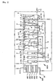
- FIG. 1 is a detailed view of a sludge treatment apparatus in an oxidized and dissolved air floating way according to the present invention
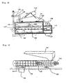
- FIG. 2 is a detailed view of a solid-liquid separating and high-speed dehydrating device in the sludge treatment apparatus according to the present invention
- FIG. 3 is a detailed view of the high-speed dehydrating device in the sludge treatment apparatus according to the present invention.
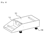
- FIG. 4 is a detailed view of a vibrator in the sludge treatment apparatus according to the present invention
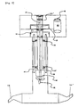
- FIG. 5 is a detailed view of one of aeration devices in the sludge treatment apparatus according to the present invention
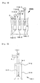
- FIG. 6 is a detailed view of a dissolved air flotation sludge treatment device in the sludge treatment apparatus according to the present invention
- FIG. 7 is a detailed view of a dissolved air flotation part in the sludge treatment apparatus according to the present invention
- FIG. 8 is a detailed view of defoamers in the sludge treatment apparatus according to the present invention
- FIG. 9 is a detailed view of a fog flotation sprayer in the sludge treatment apparatus according to the present invention
- FIG. 10 is a detailed view of another fog flotation sprayer in the sludge treatment apparatus according to the present invention
- FIG. 11 is a detailed view of a filtering device in the sludge treatment apparatus according to the present invention.
- a convey pump is denoted by 2A, a sensor 3, a convey pipe 4, an aeration device 5, an aeration pump 5-1, an aeration circulation pipe 6, an expiration pipe 7, a sludge moving pipe 9, a circulation through hole 10, overpass pipes 10-1 and 10-2, a lower overpass pipe 10-3, defoamers 11A-1, 11A-2, and 11A-3, a fog flotation treatment device 12, a solid (sludge) discharging hole 13, a first dissolved air flotation part 14A-1, a second dissolved air flotation part 14A-2, a third dissolved air flotation part 14A-3, a dissolved air flotation inducing pipe 14-1, a dissolved air flotation cross pipe 1.4-2, a dissolved air flotation cross pipe lower part 14-3, a dissolved air flotation double pipe 14-4, a cover (not represented in the figure, a drain 16, an aeration motor suction pipe 17, a discharging pipe 18, aer
- a solid-liquid separating and high-speed dehydrating device 100 that separates the excretions discharged from a stable to a collecting tank in which water fills into solids and liquid
- an excretions liquid retaining tank O disposed on the lower portion of the solid-liquid separating and high-speed dehydrating device 100 for storing the separated excretions liquid
- a first treatment tank P placed on the one side of the excretions liquid retaining tank O for treating the excretions liquid passing through the excretions liquid retaining tank O
- the first treatment tank P provided with an aeration device 5 in which two aeration pumps 5-1 and one convey pump 2A are disposed in parallel relation with each other in the lower portion of the interior thereof, with an aeration motor suction pipe 17 and an aeration circulation pipe 6 each connected to the one side of each of the aeration pumps 5-1 therein for sucking and circulating the aerated liquid, with an expiration pipe 7 connected to the aeration circulation pipe 6 in
- the second treatment tank Q which is formed on the one side of the fog flotation treatment device 12 of the first treatment tank P, treats the excretions liquid flowing from the first treatment tank P by means of an overpass pipe 10-1.
- the second treatment tank Q is provided with an aeration device 5 in which one aeration pump 5-1 and one convey pump 2A are disposed in parallel relation with each other in the lower portion of the interior thereof, with an aeration motor suction pipe 17 and an aeration circulation pipe 6 each connected to the one side of the aeration pump 5-1 therein for sucking and circulating the aerated liquid, with an expiration pipe 7 connected to the aeration circulation pipe 6 in the lower portion from the upper portion thereof, with a drain 16 disposed on the other side of the lower portion thereof for discharging the liquid filled therein if necessary, with an overpass pipe 10-2 disposed on the one side of the intermediate part of the upper portion thereof for passing the aerated liquid to a third treatment tank R, with the fog flotation treatment device 12 that is
- the third treatment tank R which is formed on the one side of the second treatment tank Q, treats the excretions liquid of the second treatment tank Q flowing through the one side convey pipe 4 of the fog flotation treatment device 12 and the overpass pipe 10-2.
- the third treatment tank R is provided with an aeration device 5 in which one aeration pump 5-1 is disposed in the lower portion of the interior thereof, with an aeration motor suction pipe 17 and an aeration circulation pipe 6 each connected to the one side of the aeration pump 5-1 for sucking and circulating the aerated liquid, with an expiration pipe 7 connected to the aeration circulation pipe 6 in the lower portion from the upper portion thereof, with a drain 16 disposed on the other side of the lower portion thereof for discharging the liquid filled therein if necessary, with a sludge convey pipe 9 placed on the one side of the upper portion thereof, and with a third defoamer 11A-3 of the dissolved air flotation treatment tank S connected by virtue of the sludge convey pipe 9.
- a dissolved air flotation sludge eliminating device 400A which is formed on the one side of the third treatment tank R, includes the three defoamers 11A-1, 11A-2 and 11A-3 and three dissolved air flotation parts 14A-1, 14A-2 and 14A-3 correspondingly thereto, each of which is connected by a dissolved air flotation inducing pipe 14-1. Further, the device 400A is provided with a sludge discharging pipe 15 for discharging the treated liquid in the three dissolved air flotation parts 14A-1, 14A-2 and 14A-3 to the dissolved air flotation treatment tank S and with a lower overpass pipe 10-3 for passing the treated liquid to a filtering device 500.
- the filtering device 500 is disposed on the one side of the dissolved air flotation treatment tank S for filtering the treated liquid flowing through the lower overpass pipe 10-3, the filtering device 500 having an active carbon layer 501 and a sand layer 502 piled in turn therein and a discharging pipe 18 formed on the upper portion thereof for discharging the treated liquid to the outside.
- FIG. 2 is a detailed view of the solid-liquid separating and high-speed dehydrating device 100.
- the device 100 includes an excretions inlet 110, a water supply pipe 109, a vibrator 101 and a vibrating plate screen 102.
- On the lower end of the device 100 are provided a separated and dewatered excretions retaining tank 112 and a water pressure sprayer 103 connected to a pipe formed of a SUS net of 2mm.
- a gas generating screw 104 is formed on the lower portion of the water pressure sprayer 103, and a gas eliminating retaining tank 113 and a discharging water pipe 107 are formed on the lower portion of the gas generating screw 104.
- a screw type high speed dehydrating part 108 and a gas generating screw motor 111 On the side portion of the above-mentioned parts are provided a screw type high speed dehydrating part 108 and a gas generating screw motor 111, and on the other side portion thereof is provided a gas emitting pipe and fan
- FIG. 3 is a detailed view of a high-speed fermenting dehydrating part 108, which is provided with an excretions inlet 121, a gas generating screw motor 114, a mechanical sealing 122 disposed on the connected portion between the motor and the dehydrating part, eight knife edges 124, an external net (not represented in the figure), the SUS net 127, a sludge discharging hole 126, and a vibrating rubber plate 123 disposed on the lower support stand of the dehydrating part.
- FIG. 4 is a detailed view of the vibrator 101, which is provided with the vibrating plate screen 102 of 0.1 m 2 in thickness on the lower portion thereof.
- FIG. 5 is a detailed view of the aeration device 5.
- the aeration device 5 is provided with a motor having aeration device belt connecting holes 46 and 46' connected by a belt with an aeration shaft 47, on the upper portion thereof, and with an aeration impeller 48 disposed on the lower portion of the aeration shaft 47 in the interior of an aeration cylinder 31.
- the aeration device 5 is provided with eight air inlets 49 arranged around the aeration shaft 47, a suction hole 50 formed on the lower portion of the intermediate part of the aeration cylinder 31, bushings 51 and 51' rotating the aeration cylinder 31, a heater 52 disposed on the upper portion of the aeration cylinder 31, ejecting pipes 54 and 54' mounted horizontally on the lower portion of the aeration cylinder 31, and a blower 31 disposed from the upper portion of the aeration device 5 and to the upper portion of the aeration cylinder 31.
- FIG. 6 is a detailed view of the dissolved air flotation sludge eliminating device 400A, which is installed in the dissolved air flotation treatment tank S.
- the device 400A is provided with the first unit that is comprised of the first defoamer 11A-1 connected by means of the sludge moving pipe 9 to the first treatment tank P and the first dissolved air flotation part 14A-1 disposed in the interior of the dissolved air flotation treatment tank S and connected to the lower portion of the first defoamer 11A-1 by the dissolved air flotation inducing pipe 14-1, with the second unit that is comprised of the second defoamer 11A-2 connected by means of the sludge moving pipe 9 to the second treatment tank Q and the second dissolved air flotation part 14A-2 disposed in the interior of the dissolved air flotation treatment tank S and connected to the lower portion of the second defoamer 11A-2 by the dissolved air flotation inducing pipe 14-1, and with the third unit that is comprised of the third defoamer 11A-3 connected by means of the sludge moving pipe 9 to the third treatment tank R and the third dissolved air flotation part 14A-3 disposed in the interior of the
- the first dissolved air flotation part 14A-1, the second dissolved air flotation part 14A-2, and the third dissolved air flotation part 14A-3 are independently arranged in the parallel relation with each other and connected to the lower portions of the first to third defoamers 11A-1 to 11A-3 by means of each of the dissolved air flotation inducing pipes 14-1.
- Each of the first to third dissolved air flotation parts 14A-1 to 14A-3 is provided with a dissolved air flotation cross pipe 14-2 connected to the dissolved air flotation inducing pipe 14-1, a dissolved air flotation cross lower pipe 14-3 extended from the lower portion of the dissolved air flotation cross pipe 14-2 and opened on the lower portion thereof, a dissolved air flotation double pipe 14-4 having a double form to surround the dissolved air flotation cross pipe 14-2 and opened on the lower portion thereof, and a cover (not represented in the figure) formed on the outside of the dissolved air flotation double pipe 14-4.
- FIG. 8 is a detailed view of the defoamer 11A-1, which is provided with a defoamer shaft 27 connected to a defoamer belt connecting hole 25 of a motor by a belt, a second defoamer impeller 27' disposed on the lower portion of the defoamer shaft 27, and a first defoamer impeller 28 disposed on the intermediate portion of the defoamer shaft 27.
- the second defoamer impeller 27' is smaller by 1/2 in size than the first defoamer impeller 28.
- a reference numeral 29 represents a bearing and 30 represents a motor fixing hole.
- FIGS. 9 and 10 are detailed views for a fog flotation sprayer in the sludge treatment apparatus according to the present invention.
- the fog flotation sprayer is provided with a foams moving pipe A through which foams flow, a spraying part formed on the one side of the upper portion of the foams moving pipe A, an air moving pipe B and an air moving portion formed on the side portion of the one side of the foam moving pipe A and on the lower portion of a wing 205 of the spraying part, an oxygen supply pipe 206 for preventing the vacuum state of the wing 205 and for supplying oxygen at the time of spraying fog, and an outlet 211 having an air contact part C on which air is met with the foams such that the foams are broken and ejected in a fog form.
- the spraying part which is formed horizontally on the upper portion of the foams moving pipe A, is provided with a motor 201, a connector 209 connected to the motor 201, a wing shaft 204 connected to the connector 209, the wing 205 formed on the end of the wing shaft 204, and an oil seal 203 formed on the external surface of the wing shaft 204 and surrounding the wing shaft 204 by bearings 202 and 202'.
- the air moving portion which is formed on the one side of the foams moving pipe A, is provided with a fan 207 and the air moving pipe B through which the air produced from the fan 207 is passed.
- the filtering device 500 is provided with the sand layer 502 formed on the lowermost portion thereof and the active carbon layer 501 formed on the upper surface of the sand layer 502, which layers are formed three times and with the discharging hole 18 formed on the upper portion thereof. If the liquid flows from the lower overpass pipe 10-3 connected to the lower portion of the dissolved air flotation treatment tank S, it is raised upwardly and passed through the sand layer 502 and the active carbon layer 501 three times such that it is filtered and discharged through the discharging hole 18.
- the excretions of the water tank are separated into solids and liquid through the solid-liquid separating and high-speed dehydrating device 100, and the separated solids are discharged through a solid excretions discharging hole 13 and used as fertilizer.
- the separated liquid excretions are over-passed to the first treatment tank P from the liquid excretions retaining tank O and are treated by the aeration device 5 in which the two aeration pumps 5-1 and the one convey pump 2A are disposed in parallel relation with each other in the first treatment tank P, such that it has a density of BOD and SS having a predetermined value wherein when the flowing water is 80,000, it is 15,000 or less.
- the part of the liquid excretions is conveyed to the second treatment tank Q on the side surface through the overpass pipe 10-1, and the foams thereof are conveyed to the dissolved air flotation treatment tank S through the sludge moving pipe 9 formed on the upper portion thereof and connected to the first defoamer 11A-1 of the dissolved air flotation treatment tank S, and another part of the liquid excretions is treated to the fog flotation treatment device 12 connected by the convey pipe 4 to the convey pump 2A of the aeration device 5 on the lower portion of the first treatment tank P and is then conveyed to the second treatment tank Q.
- the liquid excretions treated from the first treatment tank P are treated in the second treatment tank Q by the aeration device 5 in which the one aeration pump 5-1 and the one convey pump 2A are disposed in parallel relation with each other and the fog flotation treatment device 12 disposed on the one side of the upper portion thereof, such that the treated liquid has densities of BOD and SS having a predetermined value wherein it is between 15,000 and 50,000.
- the treated liquid is over-passed to the third treatment tank R by the overpass pipe 10-1 formed on the one side of the intermediate upper portion of the second treatment tank Q, and the foams thereof are conveyed to the second defoamer 11A-2 of the dissolved air flotation treatment tank S through the sludge moving pipe 9 formed on the one side of the upper portion thereof.
- the liquid excretions treated from the second treatment tank Q are treated in the third treatment tank R by the aeration device 5 in which the one aeration pump 5-1 is disposed and by the fog flotation treatment device 12.
- the foams are conveyed to the third defoamer 11A-3 of the dissolved air flotation treatment tank S through the sludge moving pipe 9 formed on the upper portions thereof and completely removed, with a result that the ratio of eliminating the sludge is 90 % or more.
- the liquid in the third treatment tank R is discharged through the drain 16.
- the foams conveyed through the sludge moving pipe 9 from each of the first to third treatment tanks P, Q, and R are treated in the sludge eliminating device 400A having the three sets comprised of the first to third defoamers 11A-1, 11A-2, and 11A-3 and the first to third dissolved air flotation parts 14A-1, 14A-2, and 14A-3.
- the treated liquid is conveyed through the lower overpass pipe 10-3 to the filtering device 500 disposed on the one side of the dissolved air flotation treatment tank S, is passed from the lower portion to upper portion of the filtering device 500 in which the active carbon layer 501 and the sand layer 502 are in turn formed, and is discharged through the discharging pipe 18. If the filtered liquid is not discharged by an unexpected accident, or if necessary, it is returned to the first treatment tank P through a returning pipe connected to the discharging pipe 18 and then retreated. And, the filtered liquid can be discharged directly through the drain 16 formed on the lower portion of each of the treatment tanks P, Q, R, and S.
- the waste excretions are discharged from the excretions inlet 110 of the solid-liquid separating and high-speed dehydrating device 100, and at the same time, water is supplied from the water supply pipe 109.
- the waste excretions and the water are induced to the vibrator 101 and the vibrating plate screen 102 and partially conveyed to the lower portion of the solid-liquid separating and high-speed dehydrating device 100 by the vibrating plate screen 102 by the operation of the vibrator 101.
- the separated liquid excretions are moved through the water pressure of the water pressure sprayer 103 connected to the pipe formed of the SUS net 127 and is then conveyed to the separated and dewatered excretions retaining tank 112 and to the gas eliminating retaining tank 113, where the containing values of ammonia, phosphorus, or methane mixed with the liquid excretions are lowered by using a net of 3m 2 .
- the gas generating screw 104 disposed in the separated and dewatered excretions retaining tank 112 is adapted to rotate by the gas generating screw motor 113 to separate the liquid excretions conveyed through the water pressure sprayer 103 such that the methane gas mixed in the liquid excretions is separated.
- the offensive odor and the methane gas are eliminated in the preparation fermenting tank upon movement to the aeration circulation pipe 6, and the gas emitting pipe and fan 105 is adapted to discharge the gas generated from the gas eliminating retaining tank 113 and the separated gas by the gas generating screw 104 to the outside.
- the sludge is dissolved by means of the eight knife edges 124 disposed on the motor 115 and the high-speed dehydrating unit 108 such that it can be easily fermented at a high speed, and the dewatered wastewater is discharged through the external net 125 and the SUS net 127 and at the same time evaporated.
- the fermented sludge is discharged through the sludge discharging hole 126.
- the gas is stored in the gas eliminating retaining tank 113 and then discharged through the gas emitting pipe and fan 105.
- the aeration shaft 47 connected to the aeration device belt connecting holes 46 and 46' and the aeration impeller 48 disposed on the lower portion of the aeration shaft 47 start to rotate.
- the aeration impeller 48 disposed in the interior of the aeration cylinder 31 rotates, air flows to the eight air inlets 49 from the blower 52 on the upper portion of the eight air inlets 49.
- the suction hole 50 is formed on the intermediate lower portion of the aeration cylinder 31, and as the aeration cylinder 31 rotates by the bushings 51 and 51', the liquid excretions flow to the suction hole 50 and come in contact with the air from the air inlet 49.
- the aeration impeller 48 By the operation of the aeration impeller 48, the liquid excretions and the air are considerably agitated and are forced to be discharged by the guide of the discharging pipe 24 disposed horizontally on the lower portion of the aeration cylinder 31, such that the liquid excretions can be well mixed with the existing ones.
- the aeration cylinder 31 may be provided with a heater 32 for adjustment to a temperature in a range between 50 and 65 °C where microorganisms are well grown, on the upper portion thereof.
- the normal temperature thereof is in a range between 38 and 40 °C.
- the dissolved air flotation sludge eliminating device 400A According to the operation method of the dissolved air flotation sludge eliminating device 400A, as shown in FIG. 6 , if the sludge liquid that is aerated in each of the treatment tanks P, Q and R is induced to the dissolved air flotation inducing pipe 14-1 through the sludge moving pipe 9, it is conveyed to each of the defoamers 11A-1, 11A-2, and 11A-3 on the upper portion of the dissolved air flotation inducing pipe 14-1.
- Each of the defoamers 11A-1, 11A-2, and 11A-3 connects the defoamer shaft 27 to the defoamer belt connecting hole 25 of the motor by a belt, and forms the second defoamer impeller 27' on the lowermost end of the defoamer shaft 27 and the second defoamer impeller 28 on the intermediate portion thereof.
- the defoamer shaft 27 and the impellers 27' and 28 connected thereto are allowed to evaporate the minute particles of the broken liquid, and if the foams are raised toward the center by the rotation of the first defoamer impeller 28, they are broken by the second defoamer impeller 27' and changed into the sludge liquid.
- the sludge liquid is conveyed to the dissolved air flotation cross pipe 14-2 of each of the first to three dissolved air flotation parts 14A-1 to 14A-3 connected through the dissolved air flotation inducing pipe 14-1.
- the operation method for one of the three dissolved air flotation parts will be explained.
- the foams that haven't been removed are gathered and eliminated on the extended portion formed on the intermediate portion of the dissolved air flotation cross pipe 14-2, and the sludge liquid is kept moved to the lower portion thereof and is passed through the dissolved air flotation cross lower part 14-3. After it reaches the dissolved air flotation double pipe 14-4 opened on the lower portion thereof, the foams that haven't yet removed are raised and gathered on the top portion of the dissolved air flotation double pipe 14-4, on which they are removed.
- the sludge liquid is conveyed through the lower portion of the dissolved air flotation double pipe 14-4 within the cover 14-5 formed on the external surface of the dissolved air flotation double pipe 14-4 and is then discharged to the dissolved air flotation treatment tank S via the sludge discharging pipe 15 formed on the one side of the cover 14-5.
- the connector 209 connected to the motor 201 and the wing 205 formed on the end portion of the wing shaft connected to the connector 209 start to rotate, and at the same time, the motor 208 and the fan 207 which are formed on the one side of the foams moving pipe A operate such that air is moved upward through the air moving pipe B.
- the air conveyed through the air moving pipe B serves as an ejector such that the foams flow along the foams moving pipe A and move while contacting with the wing 205 rotating.
- the foams are changed into a fog form by the air conveyed through the air moving pipe B and then sprayed.
- the oxygen supply pipe 206 that is formed on the upper portion of the motor supplies oxygen to the fog sprayed for the purpose of preventing the rear portion of the wing 205 from being in a vacuum state.
- a sludge treatment apparatus in oxidized and dissolved air flotation manners that changes a biological livestock excretions treatment used in the conventional practice into a physicochemical livestock excretions treatment, thereby making it possible to reduce the excretions treatment expense to a quite low extent.
- microorganisms this is achieved by dissolving the 100% livestock excretions and reducing the weight thereof and using mechanical devices, also, this is achieved in a series of continuous and automatic treatments, whereby treatment performance is advanced, the excretions, the microorganisms and air are well mixed by using aeration devices, and the foams are removed by using defoamers, such that the yellow soil-like fermented excretions that don't have any offensive odor can be reused for making stables clean.
Landscapes
- Chemical & Material Sciences (AREA)
- Chemical Kinetics & Catalysis (AREA)
- Engineering & Computer Science (AREA)
- Life Sciences & Earth Sciences (AREA)
- Biotechnology (AREA)
- Environmental & Geological Engineering (AREA)
- Water Supply & Treatment (AREA)
- Organic Chemistry (AREA)
- Hydrology & Water Resources (AREA)
- Dispersion Chemistry (AREA)
- Treatment Of Sludge (AREA)
- Physical Water Treatments (AREA)
- Electromechanical Clocks (AREA)
- Soil Working Implements (AREA)
- Catching Or Destruction (AREA)
- Eye Examination Apparatus (AREA)
Claims (6)
- Schlammbehandlungsapparat in einem oxidierten Flotierweg mit gelöster Luft, wobei der Apparat Folgendes umfasst:- ein Feststoff-Flüssigkeitstrennungs- und Hochgeschwindigkeitsentwässerungsgerät (100), das die Exkrete, die aus einem Stall in einen Sammelbrunnen abgelassen werden, in dem Wasser zu den Feststoffen und der Flüssigkeit eingefüllt wird, trennt,- ein Exkretflüssigkeits-Rückhaltebecken (O), das im unteren Abschnitt des Feststoff-Flüssigkeitstrennungs- und Hochgeschwindigkeitsentwässerungsgeräts (100) zum Lagern der abgetrennten Exkretflüssigkeit angeordnet ist,- ein erstes Behandlungsbecken (P), dem die Exkretbehandlungsflüssigkeit aus dem Exkretflüssigkeits-Rückhaltebecken (O) auf der einen Seite davon zugeleitet wird, das ein Belüftungsgerät (5) aufweist, in dem zwei Belüftungspumpen (5-1) und eine Förderpumpe (2A) in parallelem Verhältnis zu einander im unteren Abschnitt des Inneren des ersten Behandlungsbeckens (P) angeordnet sind, das eine Schlammförderröhre (9) aufweist, die im oberen Abschnitt davon angeordnet ist, zum Verbinden mit einem ersten Entschäumer (11A-1), der ein Nebelflotationsbehandlungsgerät (12) aufweist, das im oberen Abschnitt davon zum Anschließen an die Förderpumpe (2A) durch eine Förderröhre (4) angeordnet ist und eine Überleitröhre (10-1) zum Fördern des behandelten Schlamms zu einem zweiten Behandlungsbecken (Q) aufweist; wobei das zweite Behandlungsbecken (Q) ein Belüftungsgerät (5) aufweist, in dem eine Belüftungspumpe (5-1) und eine Förderpumpe (2A) in parallelem Verhältnis zu einander im unteren Abschnitt des Inneren davon angeordnet sind, das eine Schlammförderröhre (9) aufweist, die im oberen Abschnitt davon angeordnet ist, zum Verbinden mit einem zweiten Entschäumer (11A-2), der ein Nebelflotationsgerät (12) aufweist, das im oberen Abschnitt davon zum Anschließen an die Förderpumpe (2A) durch eine Förderröhre (4) angeordnet ist und eine Überleitröhre (10-2) zum Fördern des behandelten Schlamms zu einem dritten Behandlungsbecken (R) aufweist; wobei das dritte Behandlungsbecken (R) eine Belüftungspumpe (5-1) aufweist, die im unteren Abschnitt des Inneren davon angeordnet ist, eine Schlammförderröhre (9) aufweist, die im oberen Abschnitt davon angeordnet ist zum Verbinden mit einem dritten Entschäumer (11A-3) und ein Nebelflotationsbehandlungsgerät (12) aufweist, das auf der einen Seite des oberen Abschnitts davon angeordnet ist;- ein Gerät zur Entfernung von Flotationsschlamm mit gelöster Luft (400A), das im Inneren eines Flotationsbehandlungsbeckens mit gelöster Luft (S) installiert ist, das auf der einen Seite des dritten Behandlungsbeckens (R) gebildet ist, in dem drei unabhängige Einheiten in parallelem Verhältnis zu einander stehen, in denen die entgültigen Schäume und Schlamm behandelt werden, wobei die erste Einheit aus dem ersten Entschäumer (11A-1) und einem Flotationsteil mit gelöster Luft (14-1) besteht, das an das untere Teil des ersten Entschäumers (11A-1) angeschlossen ist, die zweite Einheit aus dem zweiten Entschäumer (11A-2) und einem Flotationsteil mit gelöster Luft (14A-2) besteht, das an das untere Teil des zweiten Entschäumers (11A-2) angeschlossen ist, und die dritte Einheit aus dem dritten Entschäumer (11A-3) und einem Flotationsteil mit gelöster Luft (14A-3) besteht, das an das untere Teil des dritten Entschäumers (11A-3) angeschlossen ist; und- einem Filtriergerät (500), das am Seitenabschnitt einer niedriger gelegenen Überleitröhre (10-3) angeordnet ist und Aktivkohleschichten (501) und Sandschichten (502), die nacheinander darin gebildet sind, und eine Ablassröhre (18) zum Ablassen der filtrierten Flüssigkeit aufweist.
- Apparat nach Anspruch 1, wobei das erste Behandlungsbecken (P) mit einem Belüftungsgerät (5) ausgestattet ist, in dem die beiden Belüftungspumpen (5-1) und die eine Förderpumpe (2A) in parallelem Verhältnis zu einander im unteren Abschnitt des Inneren davon angeordnet sind, wobei eine Belüftungsmotorsaugröhre (17) und eine Belüftungszirkulationsröhre (6) jeweils an die eine Seite von jeder der Belüftungspumpen (5-1) darin angeschlossen sind zum Saugen und Zirkulieren der belüfteten Flüssigkeit, wobei eine Ablaufpumpe (7) an die Belüftungszirkulationsröhre (6) im unteren Abschnitt des oberen Abschnitts davon angeschlossen ist, wobei ein Ausflussrohr (16) an der anderen Seite des unteren Abschnitts davon nötigenfalls zum Ablassen der darin eingefüllten Flüssigkeit angeordnet ist, wobei eine Überleitröhre (10-1) an der anderen Seite des Zwischenteils des dortigen oberen Abschnitts zum Führen der belüfteten Flüssigkeit zum zweiten Behandlungsbecken (Q) angeordnet ist, wobei die Schlammbeförderungsröhre (9) auf dem oberen Abschnitt davon positioniert ist, wobei der erste Entschäumer (11A-1) des Flotationsbehandlungsbeckens mit gelöster Luft (S) durch die Schlammbeförderungsröhre (9) angeschlossen ist und wobei das Nebelflotationsbehandlungsgerät (12) auf der anderen Seite des oberen Abschnitts davon angeordnet ist, wobei das Nebelflotationsbehandlungsgerät (12) an die Förderröhre (2A) darin des Belüftungsgeräts (5) durch die Förderröhre (4) an der einen Seite davon angeschlossen ist und Ablassen der behandelten Exkretflüssigkeit zum zweiten danebengelegenen Behandlungsbecken (Q) durch die Förderröhre (4), die an die andere Seite angeschlossen ist.
- Apparat nach Anspruch 1, wobei das zweite Behandlungsbecken (Q), das auf der einen Seite des Nebelflotationsbehandlungsgeräts (12) des ersten Behandlungsbeckens (P) gebildet ist, die Exkretflüssigkeit, die aus dem ersten Behandlungsbecken (P) durch die Überleitröhre (10-1) fließt, behandelt, wobei das zweite Behandlungsbecken (Q) mit Folgendem ausgestattet ist: mit dem Belüftungsgerät (5), in dem die eine Belüftungspumpe (5-1) und die eine Förderpumpe (2A) in parallelem Verhältnis zu einander im unteren Abschnitts des Inneren davon angeordnet sind, mit einer Belüftungsmotorsaugröhre (17) und einer Belüftungszirkulationsröhre (6), die jeweils an die eine Seite der Belüftungspumpe (5-17) darin angeschlossen sind zum Saugen und Zirkulieren der belüfteten Flüssigkeit, mit einer Ablaufpumpe (7), die an die Belüftungszirkulationspumpe (6) im unteren Abschnitt des oberen Abschnitts davon angeschlossen ist, mit einem Ausflussrohr (16), das an der anderen Seite des unteren Abschnitts davon nötigenfalls zum Ablassen der darin eingefüllten Flüssigkeit angeordnet ist, mit der Überleitröhre (10-1), die an der einen Seite des Zwischenteils des dortigen oberen Abschnitts davon zum Führen der belüfteten Flüssigkeit zum dritten Behandlungsbecken (R) angeordnet ist, mit dem Nebelflotationsbehandlungsgerät (12), das im oberen Abschnitt davon zum Behandeln der Exkretflüssigkeit, die dorthin fließt, angeordnet ist, mit der Schlammbeförderungsröhre (9), die auf der einen Seite des oberen Abschnitts davon positioniert ist, mit dem zweiten Entschäumer (11A-2) des Flotationsbehandlungsbeckens mit gelöster Luft (S), das durch die Schlammförderpumpe (9) angeschlossen ist, und der Förderröhre (4), die die Förderpumpe (2A) darin an das Nebelflotationsbehandlungsgerät (12) des dritten Behandlungsbeckens (R) neben dem zweiten Behandlungsbecken (Q) anschließt.
- Apparat nach Anspruch 1, wobei das dritte Behandlungsbecken (R), das auf der einen Seite des zweiten Behandlungsbeckens (Q) gebildet ist, die Exkretflüssigkeit des zweiten Behandlungsbeckens (Q) behandelt, die durch Förderröhre auf der einen Seite (4) des Nebelflotationsbehandlungsgeräts (12) und die Überleitröhre (10-2) fließt, wobei das dritte Behandlungsbecken (R), das mit dem Belüftungsgerät (5) ausgestattet ist, in dem die eine Belüftungspumpe (5-1) im unteren Abschnitt des Inneren davon angeordnet ist, mit einer Belüftungsmotorsaugröhre (17) und einer Belüftungszirkulationsröhre (6) jeweils an die eine Seite der Belüftungspumpe (5-1) darin angeschlossen sind zum Saugen und Zirkulieren der belüfteten Flüssigkeit, wobei eine Ablaufpumpe (7) an die Belüftungszirkulationspumpe (6) im unteren Abschnitt des oberen Abschnitts davon angeschlossen ist, wobei ein Ausflussrohr (16) an der anderen Seite des unteren Abschnitts davon nötigenfalls zum Ablassen der darin eingefüllten Flüssigkeit angeordnet ist, wobei die Schlammförderröhre (9) auf der einen Seite des oberen Abschnitts davon positioniert ist und wobei der dritte Entschäumer (11A-3) des Flotationsbehandlungsbecken mit gelöster Luft (S) durch die Schlammförderröhre (9) angeschlossen ist.
- Apparat nach Anspruch 1, wobei das Gerät der Flotationsschlammbeseitigung mit gelöster Luft (400A), das in dem Flotationsbehandlungsbecken mit gelöster Luft (S) angeordnet ist, mit Folgendem ausgestattet ist: der ersten Einheit ausge4stattet wird, die den ersten Entschäumer (11A-1), der durch die Schlammförderröhre (9) an das erste Behandlungsbecken (P) und den ersten Flotationsteil mit gelöster Luft (14-1) angeschlossen ist, der im Inneren des Flotationsbehandlungsbeckens mit gelöster Luft (S) angeordnet und an den unteren Abschnitt des ersten Entschäumers (11A-1) durch die die Flotation gelöster Luft induzierende Röhre (14-1) mit der zweiten Einheit, die aus dem zweiten Entschäumer (11A-2) besteht, verbunden ist, der durch die Schlammförderröhre (9) an das zweite Behandlungsbecken (Q) and das zweite Flotationsteil mit gelöster Luft (14A-2) angeschlossen ist, das im Inneren des Flotationsbehandlungsbeckens mit gelöster Luft (S) angeordnet und mit dem unteren Abschnitt des zweiten Entschäumers (11A-2) durch die die Flotation von gelöster Luft induzierende Röhre (14-1) angeschlossen ist, und mit der dritten Einheit ausgestattet ist, die aus dem dritten Entschäumer (11A-3) besteht, der durch die Schlammbeförderungsröhre (9) an das dritte Behandlungsbecken (R) und das dritte Flotationsteil mit gelöster Luft (14A-3) angeschlossen ist, das im Inneren des Flotationsbehandlungsbeckens mit gelöster Luft (S) angeordnet und an den unteren Abschnitt des dritten Entschäumers (11A-2) durch die die Flotation gelöster Luft induzierende Röhre (14-1) angeschlossen ist, wobei das erste Flotationsteil mit gelöster Luft (14A-1), das zweite Flotationsteil mit gelöster Luft (14A-2) und das dritte Flotationsteil mit gelöster Luft (14A-3) unabhängig in parallelem Verhältnis zu einander angeordnet und an die unteren Abschnitte der ersten bis dritten Entschäumer (11A-1 bis 11A-3) durch jede der die Flotation gelöster Luft induzierende Röhre (14-1) angeschlossen sind, wobei jeder der ersten bis dritten Flotationsteile mit gelöster Luft (14A-1 bis 14A-3) mit einer Flotationskreuzröhre mit gelöster Luft (14-2) ausgestattet ist, die an die die Flotation gelöster Luft induzierene Röhre (14-1) angeschlossen ist, eine untere Flotationskreuzröhre mit gelöster Luft (14-3), die sich von dem unteren Abschnitt der Flotationskreuzröhre mit gelöster Luft (14-2) erstreckt und sich in den unteren Abschnitt davon öffnet, einer Flotationsdoppelröhre mit gelöster Luft (14-4), die eine doppelte Form zum Umgeben der Flotationskreuzröhre mit gelöster Luft (14-2) aufweist und sich in den unteren Abschnitt davon öffnet, und eine Abdeckung (14-5), die auf der Außenseite der Flotationsdoppelröhre mit gelöster Luft (14-4) gebildet ist, wobei jeder der ersten bis dritten Entschäumer (11A-1 bis 11A-3) mit einer Entschäumerwelle (27) ausgestattet ist, die an ein Entschäumerbandverbindungsloch (25) eines Motors durch ein Band angeschlossen ist, ein Laufrad eines zweiten Entschäumers (27') auf dem unteren Abschnitt der Entschäumerwelle (27) angeordnet und halb so groß ist wie das Laufrad des ersten Entschäumers (28), und ein Laufrad der ersten Entschäumers (28) auf dem Zwischenabschnitt der Entschäumerwelle (27) angeordnet ist.
- Apparat nach Anspruch 1, wobei:- das Feststoff-Flüssigkeitstrennungs- und Hochgeschwindigkeitsentwässerungsgerät (100) einen Exkreteinlass (110), eine Wasserspeiseröhre (109), einen Rüttler (101) und ein von unten nach oben vibrierendes Plattensieb (102) umfasst;- am unteren Ende des Geräts(100) ein getrenntes und entwässertes Exkretaufnahmebecken (112) und ein Wasserdrucksprühgerät (103), das an eine Röhre angeschlossen ist, die aus einem SUS-Netz von 2 mm gebildet ist, bereitgestellt sind;- eine Gaserzeugungsschnecke (104)im unteren Abschnitt des Wasserdrucksprühgeräts (103) gebildet ist und ein Gaseliminationshaltetank (113) und eine ablassende Wasserröhre (107) im unteren Abschnitt der Gaserzeugungsschnecke (104) gebildet sind;- in einem Seitenabschnitt der oben erwähnten Teile ein Hochgeschwindigkeitshydratisierteil (108) und ein gaserzeugender Schneckenmotor (111) und im anderen Seitenabschnitt davon eine Gasabgaberöhre und ein Gebläse (105) bereitgestellt sind.
Applications Claiming Priority (3)
| Application Number | Priority Date | Filing Date | Title |
|---|---|---|---|
| KR10-2002-0020494A KR100436973B1 (ko) | 2002-04-15 | 2002-04-15 | 전분제거장치 |
| KR2002020494 | 2002-04-15 | ||
| PCT/KR2002/000752 WO2003089375A1 (en) | 2002-04-15 | 2002-04-24 | Apparatus for stock raising |
Publications (3)
| Publication Number | Publication Date |
|---|---|
| EP1494970A1 EP1494970A1 (de) | 2005-01-12 |
| EP1494970A4 EP1494970A4 (de) | 2006-08-16 |
| EP1494970B1 true EP1494970B1 (de) | 2008-10-08 |
Family
ID=19720352
Family Applications (1)
| Application Number | Title | Priority Date | Filing Date |
|---|---|---|---|
| EP02718703A Expired - Lifetime EP1494970B1 (de) | 2002-04-15 | 2002-04-24 | Vorrichtung zur aufzucht von vieh |
Country Status (6)
| Country | Link |
|---|---|
| EP (1) | EP1494970B1 (de) |
| KR (1) | KR100436973B1 (de) |
| AT (1) | ATE410397T1 (de) |
| AU (1) | AU2002249686A1 (de) |
| DE (1) | DE60229301D1 (de) |
| WO (1) | WO2003089375A1 (de) |
Cited By (1)
| Publication number | Priority date | Publication date | Assignee | Title |
|---|---|---|---|---|
| RU2531379C1 (ru) * | 2013-08-16 | 2014-10-20 | Олег Савельевич Кочетов | Флотационно-фильтрационная установка |
Families Citing this family (5)
| Publication number | Priority date | Publication date | Assignee | Title |
|---|---|---|---|---|
| CN100371257C (zh) * | 2005-03-28 | 2008-02-27 | 哈尔滨工业大学 | 逆流式气浮滤池 |
| CN1319867C (zh) * | 2005-03-31 | 2007-06-06 | 哈尔滨工业大学 | 气浮滤池 |
| WO2008030378A1 (en) | 2006-09-07 | 2008-03-13 | Sifers Don S | Method and apparatus for controlling fecal odors |
| CN107758910A (zh) * | 2016-08-18 | 2018-03-06 | 宜兴市天马环保工程有限公司 | 集成式自动高效沉淀气浮装置 |
| ES2703975B2 (es) * | 2019-02-15 | 2019-11-05 | Usandizaga Jaime Maria Segovia | Sistema para depurar purines |
Citations (1)
| Publication number | Priority date | Publication date | Assignee | Title |
|---|---|---|---|---|
| KR100306224B1 (ko) * | 1999-05-12 | 2001-09-13 | 김경원 | 축산분뇨의 처리방법 및 장치 |
Family Cites Families (5)
| Publication number | Priority date | Publication date | Assignee | Title |
|---|---|---|---|---|
| JPS60125214A (ja) * | 1983-12-09 | 1985-07-04 | Yaskawa Electric Mfg Co Ltd | 最終沈澱池の制御方法 |
| US5693222A (en) * | 1996-05-03 | 1997-12-02 | Baker Hughes Incorporated | Apparatus and method for improved high-efficiency dissolved air flotation fluid processing |
| US6190566B1 (en) * | 1998-06-23 | 2001-02-20 | Steven N. Kolber | Treatment of waste produced by farm animals raised under confined conditions |
| JP2000140892A (ja) * | 1998-08-31 | 2000-05-23 | Nisso Plant Kensetsu Kk | 畜産動物の排泄物処理装置 |
| JP2001224905A (ja) * | 2000-02-15 | 2001-08-21 | Katsumi Iida | スクリーン型固液分離装置 |
-
2002
- 2002-04-15 KR KR10-2002-0020494A patent/KR100436973B1/ko not_active Expired - Fee Related
- 2002-04-24 AU AU2002249686A patent/AU2002249686A1/en not_active Abandoned
- 2002-04-24 AT AT02718703T patent/ATE410397T1/de not_active IP Right Cessation
- 2002-04-24 WO PCT/KR2002/000752 patent/WO2003089375A1/en not_active Ceased
- 2002-04-24 DE DE60229301T patent/DE60229301D1/de not_active Expired - Lifetime
- 2002-04-24 EP EP02718703A patent/EP1494970B1/de not_active Expired - Lifetime
Patent Citations (1)
| Publication number | Priority date | Publication date | Assignee | Title |
|---|---|---|---|---|
| KR100306224B1 (ko) * | 1999-05-12 | 2001-09-13 | 김경원 | 축산분뇨의 처리방법 및 장치 |
Cited By (1)
| Publication number | Priority date | Publication date | Assignee | Title |
|---|---|---|---|---|
| RU2531379C1 (ru) * | 2013-08-16 | 2014-10-20 | Олег Савельевич Кочетов | Флотационно-фильтрационная установка |
Also Published As
| Publication number | Publication date |
|---|---|
| KR100436973B1 (ko) | 2004-06-30 |
| EP1494970A1 (de) | 2005-01-12 |
| KR20020039289A (ko) | 2002-05-25 |
| ATE410397T1 (de) | 2008-10-15 |
| AU2002249686A1 (en) | 2003-11-03 |
| WO2003089375A1 (en) | 2003-10-30 |
| EP1494970A4 (de) | 2006-08-16 |
| DE60229301D1 (de) | 2008-11-20 |
Similar Documents
| Publication | Publication Date | Title |
|---|---|---|
| US4002561A (en) | Method and apparatus for aerobic sewage treatment | |
| US6555359B2 (en) | Process for the anaerobic treatment of flowable and nonflowable organic waste | |
| JP3960920B2 (ja) | 液体処理方法及び装置 | |
| JP2004528981A (ja) | 嫌気的消化装置、嫌気的消化方法及び消化における抑制ポリマーの使用を最小にする方法 | |
| KR100976144B1 (ko) | 가축 분뇨 처리장치 및 가축 분뇨 처리방법 | |
| JP2010000498A (ja) | スクリーン処理装置 | |
| KR20140012816A (ko) | 침전물 배출수단이 구비된 음식물쓰레기 처리장치 | |
| KR100809876B1 (ko) | 토착미생물활성화장치 | |
| KR100453806B1 (ko) | 고농도 유기성 폐수의 정화처리 장치 및 방법 | |
| EP1494970A1 (de) | Vorrichtung zur aufzucht von vieh | |
| KR100306228B1 (ko) | 축산분뇨의 처리방법 및 장치 | |
| JP3456641B2 (ja) | 生ゴミ類の微生物処理装置 | |
| CN215799050U (zh) | 施工废水回收利用装置 | |
| KR101808952B1 (ko) | 음식물 쓰레기 처리 장치 | |
| KR200307098Y1 (ko) | 토착미생물활성화장치 | |
| KR100306224B1 (ko) | 축산분뇨의 처리방법 및 장치 | |
| KR200283103Y1 (ko) | 산화부상 가압 전분제거장치 | |
| KR200283099Y1 (ko) | 산화부상 가압 전분제거장치 | |
| KR200283101Y1 (ko) | 산화부상 가압 전분제거장치 | |
| KR200307201Y1 (ko) | 토착미생물활성화장치 | |
| KR20020092876A (ko) | 토착미생물활성화장치 및 그를 이용하여 액상뇨를처리하는 방법 | |
| CN206799388U (zh) | 集装箱式可变容积一体化污水处理系统 | |
| JP2005169240A (ja) | 汚水処理設備 | |
| KR100491918B1 (ko) | 제트폭기 산화부상기 | |
| KR200175419Y1 (ko) | 축산분뇨의 처리장치 |
Legal Events
| Date | Code | Title | Description |
|---|---|---|---|
| PUAI | Public reference made under article 153(3) epc to a published international application that has entered the european phase |
Free format text: ORIGINAL CODE: 0009012 |
|
| 17P | Request for examination filed |
Effective date: 20041115 |
|
| AK | Designated contracting states |
Kind code of ref document: A1 Designated state(s): AT BE CH CY DE DK ES FI FR GB GR IE IT LI LU MC NL PT SE TR |
|
| AX | Request for extension of the european patent |
Extension state: AL LT LV MK RO SI |
|
| A4 | Supplementary search report drawn up and despatched |
Effective date: 20060713 |
|
| RIC1 | Information provided on ipc code assigned before grant |
Ipc: B01D 21/24 20060101ALI20060707BHEP Ipc: C02F 1/24 20060101AFI20031105BHEP Ipc: B03D 1/12 20060101ALI20060707BHEP Ipc: B01D 19/02 20060101ALI20060707BHEP |
|
| 17Q | First examination report despatched |
Effective date: 20071024 |
|
| GRAP | Despatch of communication of intention to grant a patent |
Free format text: ORIGINAL CODE: EPIDOSNIGR1 |
|
| GRAS | Grant fee paid |
Free format text: ORIGINAL CODE: EPIDOSNIGR3 |
|
| GRAA | (expected) grant |
Free format text: ORIGINAL CODE: 0009210 |
|
| AK | Designated contracting states |
Kind code of ref document: B1 Designated state(s): AT BE CH CY DE DK ES FI FR GB GR IE IT LI LU MC NL PT SE TR |
|
| REG | Reference to a national code |
Ref country code: GB Ref legal event code: FG4D |
|
| REG | Reference to a national code |
Ref country code: CH Ref legal event code: EP |
|
| REG | Reference to a national code |
Ref country code: IE Ref legal event code: FG4D |
|
| REF | Corresponds to: |
Ref document number: 60229301 Country of ref document: DE Date of ref document: 20081120 Kind code of ref document: P |
|
| NLV1 | Nl: lapsed or annulled due to failure to fulfill the requirements of art. 29p and 29m of the patents act | ||
| PG25 | Lapsed in a contracting state [announced via postgrant information from national office to epo] |
Ref country code: ES Free format text: LAPSE BECAUSE OF FAILURE TO SUBMIT A TRANSLATION OF THE DESCRIPTION OR TO PAY THE FEE WITHIN THE PRESCRIBED TIME-LIMIT Effective date: 20090119 Ref country code: AT Free format text: LAPSE BECAUSE OF FAILURE TO SUBMIT A TRANSLATION OF THE DESCRIPTION OR TO PAY THE FEE WITHIN THE PRESCRIBED TIME-LIMIT Effective date: 20081008 |
|
| PG25 | Lapsed in a contracting state [announced via postgrant information from national office to epo] |
Ref country code: PT Free format text: LAPSE BECAUSE OF FAILURE TO SUBMIT A TRANSLATION OF THE DESCRIPTION OR TO PAY THE FEE WITHIN THE PRESCRIBED TIME-LIMIT Effective date: 20090218 Ref country code: FI Free format text: LAPSE BECAUSE OF FAILURE TO SUBMIT A TRANSLATION OF THE DESCRIPTION OR TO PAY THE FEE WITHIN THE PRESCRIBED TIME-LIMIT Effective date: 20081008 Ref country code: NL Free format text: LAPSE BECAUSE OF FAILURE TO SUBMIT A TRANSLATION OF THE DESCRIPTION OR TO PAY THE FEE WITHIN THE PRESCRIBED TIME-LIMIT Effective date: 20081008 |
|
| PG25 | Lapsed in a contracting state [announced via postgrant information from national office to epo] |
Ref country code: BE Free format text: LAPSE BECAUSE OF FAILURE TO SUBMIT A TRANSLATION OF THE DESCRIPTION OR TO PAY THE FEE WITHIN THE PRESCRIBED TIME-LIMIT Effective date: 20081008 Ref country code: DK Free format text: LAPSE BECAUSE OF FAILURE TO SUBMIT A TRANSLATION OF THE DESCRIPTION OR TO PAY THE FEE WITHIN THE PRESCRIBED TIME-LIMIT Effective date: 20081008 |
|
| PLBE | No opposition filed within time limit |
Free format text: ORIGINAL CODE: 0009261 |
|
| STAA | Information on the status of an ep patent application or granted ep patent |
Free format text: STATUS: NO OPPOSITION FILED WITHIN TIME LIMIT |
|
| PG25 | Lapsed in a contracting state [announced via postgrant information from national office to epo] |
Ref country code: SE Free format text: LAPSE BECAUSE OF FAILURE TO SUBMIT A TRANSLATION OF THE DESCRIPTION OR TO PAY THE FEE WITHIN THE PRESCRIBED TIME-LIMIT Effective date: 20090108 Ref country code: IT Free format text: LAPSE BECAUSE OF FAILURE TO SUBMIT A TRANSLATION OF THE DESCRIPTION OR TO PAY THE FEE WITHIN THE PRESCRIBED TIME-LIMIT Effective date: 20081008 |
|
| 26N | No opposition filed |
Effective date: 20090709 |
|
| REG | Reference to a national code |
Ref country code: CH Ref legal event code: PL |
|
| PG25 | Lapsed in a contracting state [announced via postgrant information from national office to epo] |
Ref country code: LI Free format text: LAPSE BECAUSE OF NON-PAYMENT OF DUE FEES Effective date: 20090430 Ref country code: CH Free format text: LAPSE BECAUSE OF NON-PAYMENT OF DUE FEES Effective date: 20090430 |
|
| REG | Reference to a national code |
Ref country code: IE Ref legal event code: MM4A |
|
| PG25 | Lapsed in a contracting state [announced via postgrant information from national office to epo] |
Ref country code: IE Free format text: LAPSE BECAUSE OF NON-PAYMENT OF DUE FEES Effective date: 20090424 Ref country code: MC Free format text: LAPSE BECAUSE OF NON-PAYMENT OF DUE FEES Effective date: 20090430 |
|
| PG25 | Lapsed in a contracting state [announced via postgrant information from national office to epo] |
Ref country code: GR Free format text: LAPSE BECAUSE OF FAILURE TO SUBMIT A TRANSLATION OF THE DESCRIPTION OR TO PAY THE FEE WITHIN THE PRESCRIBED TIME-LIMIT Effective date: 20090109 |
|
| PG25 | Lapsed in a contracting state [announced via postgrant information from national office to epo] |
Ref country code: LU Free format text: LAPSE BECAUSE OF NON-PAYMENT OF DUE FEES Effective date: 20090424 |
|
| PGFP | Annual fee paid to national office [announced via postgrant information from national office to epo] |
Ref country code: FR Payment date: 20110502 Year of fee payment: 10 Ref country code: DE Payment date: 20110330 Year of fee payment: 10 |
|
| PG25 | Lapsed in a contracting state [announced via postgrant information from national office to epo] |
Ref country code: TR Free format text: LAPSE BECAUSE OF FAILURE TO SUBMIT A TRANSLATION OF THE DESCRIPTION OR TO PAY THE FEE WITHIN THE PRESCRIBED TIME-LIMIT Effective date: 20081008 |
|
| PGFP | Annual fee paid to national office [announced via postgrant information from national office to epo] |
Ref country code: GB Payment date: 20110421 Year of fee payment: 10 |
|
| PG25 | Lapsed in a contracting state [announced via postgrant information from national office to epo] |
Ref country code: CY Free format text: LAPSE BECAUSE OF FAILURE TO SUBMIT A TRANSLATION OF THE DESCRIPTION OR TO PAY THE FEE WITHIN THE PRESCRIBED TIME-LIMIT Effective date: 20081008 |
|
| GBPC | Gb: european patent ceased through non-payment of renewal fee |
Effective date: 20120424 |
|
| REG | Reference to a national code |
Ref country code: FR Ref legal event code: ST Effective date: 20121228 |
|
| PG25 | Lapsed in a contracting state [announced via postgrant information from national office to epo] |
Ref country code: GB Free format text: LAPSE BECAUSE OF NON-PAYMENT OF DUE FEES Effective date: 20120424 |
|
| REG | Reference to a national code |
Ref country code: DE Ref legal event code: R119 Ref document number: 60229301 Country of ref document: DE Effective date: 20121101 |
|
| PG25 | Lapsed in a contracting state [announced via postgrant information from national office to epo] |
Ref country code: FR Free format text: LAPSE BECAUSE OF NON-PAYMENT OF DUE FEES Effective date: 20120430 |
|
| PG25 | Lapsed in a contracting state [announced via postgrant information from national office to epo] |
Ref country code: DE Free format text: LAPSE BECAUSE OF NON-PAYMENT OF DUE FEES Effective date: 20121101 |