EP1495262B1 - Brennersystem mit verbesserter rauchgasrückführung - Google Patents
Brennersystem mit verbesserter rauchgasrückführung Download PDFInfo
- Publication number
- EP1495262B1 EP1495262B1 EP03744726.5A EP03744726A EP1495262B1 EP 1495262 B1 EP1495262 B1 EP 1495262B1 EP 03744726 A EP03744726 A EP 03744726A EP 1495262 B1 EP1495262 B1 EP 1495262B1
- Authority
- EP
- European Patent Office
- Prior art keywords
- burner
- fuel
- spud
- furnace
- flue gas
- Prior art date
- Legal status (The legal status is an assumption and is not a legal conclusion. Google has not performed a legal analysis and makes no representation as to the accuracy of the status listed.)
- Expired - Lifetime
Links
Images






Classifications
-
- F—MECHANICAL ENGINEERING; LIGHTING; HEATING; WEAPONS; BLASTING
- F23—COMBUSTION APPARATUS; COMBUSTION PROCESSES
- F23C—METHODS OR APPARATUS FOR COMBUSTION USING FLUID FUEL OR SOLID FUEL SUSPENDED IN A CARRIER GAS OR AIR
- F23C9/00—Combustion apparatus characterised by arrangements for returning combustion products or flue gases to the combustion chamber
-
- F—MECHANICAL ENGINEERING; LIGHTING; HEATING; WEAPONS; BLASTING
- F23—COMBUSTION APPARATUS; COMBUSTION PROCESSES
- F23C—METHODS OR APPARATUS FOR COMBUSTION USING FLUID FUEL OR SOLID FUEL SUSPENDED IN A CARRIER GAS OR AIR
- F23C6/00—Combustion apparatus characterised by the combination of two or more combustion chambers or combustion zones, e.g. for staged combustion
- F23C6/04—Combustion apparatus characterised by the combination of two or more combustion chambers or combustion zones, e.g. for staged combustion in series connection
- F23C6/045—Combustion apparatus characterised by the combination of two or more combustion chambers or combustion zones, e.g. for staged combustion in series connection with staged combustion in a single enclosure
-
- F—MECHANICAL ENGINEERING; LIGHTING; HEATING; WEAPONS; BLASTING
- F23—COMBUSTION APPARATUS; COMBUSTION PROCESSES
- F23C—METHODS OR APPARATUS FOR COMBUSTION USING FLUID FUEL OR SOLID FUEL SUSPENDED IN A CARRIER GAS OR AIR
- F23C7/00—Combustion apparatus characterised by arrangements for air supply
- F23C7/008—Flow control devices
-
- F—MECHANICAL ENGINEERING; LIGHTING; HEATING; WEAPONS; BLASTING
- F23—COMBUSTION APPARATUS; COMBUSTION PROCESSES
- F23D—BURNERS
- F23D14/00—Burners for combustion of a gas, e.g. of a gas stored under pressure as a liquid
- F23D14/02—Premix gas burners, i.e. in which gaseous fuel is mixed with combustion air upstream of the combustion zone
- F23D14/04—Premix gas burners, i.e. in which gaseous fuel is mixed with combustion air upstream of the combustion zone induction type, e.g. Bunsen burner
-
- F—MECHANICAL ENGINEERING; LIGHTING; HEATING; WEAPONS; BLASTING
- F23—COMBUSTION APPARATUS; COMBUSTION PROCESSES
- F23D—BURNERS
- F23D14/00—Burners for combustion of a gas, e.g. of a gas stored under pressure as a liquid
- F23D14/02—Premix gas burners, i.e. in which gaseous fuel is mixed with combustion air upstream of the combustion zone
- F23D14/04—Premix gas burners, i.e. in which gaseous fuel is mixed with combustion air upstream of the combustion zone induction type, e.g. Bunsen burner
- F23D14/08—Premix gas burners, i.e. in which gaseous fuel is mixed with combustion air upstream of the combustion zone induction type, e.g. Bunsen burner with axial outlets at the burner head
-
- F—MECHANICAL ENGINEERING; LIGHTING; HEATING; WEAPONS; BLASTING
- F23—COMBUSTION APPARATUS; COMBUSTION PROCESSES
- F23D—BURNERS
- F23D14/00—Burners for combustion of a gas, e.g. of a gas stored under pressure as a liquid
- F23D14/46—Details
- F23D14/48—Nozzles
- F23D14/58—Nozzles characterised by the shape or arrangement of the outlet or outlets from the nozzle, e.g. of annular configuration
-
- F—MECHANICAL ENGINEERING; LIGHTING; HEATING; WEAPONS; BLASTING
- F23—COMBUSTION APPARATUS; COMBUSTION PROCESSES
- F23D—BURNERS
- F23D14/00—Burners for combustion of a gas, e.g. of a gas stored under pressure as a liquid
- F23D14/46—Details
- F23D14/66—Preheating the combustion air or gas
-
- F—MECHANICAL ENGINEERING; LIGHTING; HEATING; WEAPONS; BLASTING
- F23—COMBUSTION APPARATUS; COMBUSTION PROCESSES
- F23L—SUPPLYING AIR OR NON-COMBUSTIBLE LIQUIDS OR GASES TO COMBUSTION APPARATUS IN GENERAL ; VALVES OR DAMPERS SPECIALLY ADAPTED FOR CONTROLLING AIR SUPPLY OR DRAUGHT IN COMBUSTION APPARATUS; INDUCING DRAUGHT IN COMBUSTION APPARATUS; TOPS FOR CHIMNEYS OR VENTILATING SHAFTS; TERMINALS FOR FLUES
- F23L7/00—Supplying non-combustible liquids or gases, other than air, to the fire, e.g. oxygen, steam
- F23L7/002—Supplying water
- F23L7/005—Evaporated water; Steam
-
- F—MECHANICAL ENGINEERING; LIGHTING; HEATING; WEAPONS; BLASTING
- F23—COMBUSTION APPARATUS; COMBUSTION PROCESSES
- F23M—CASINGS, LININGS, WALLS OR DOORS SPECIALLY ADAPTED FOR COMBUSTION CHAMBERS, e.g. FIREBRIDGES; DEVICES FOR DEFLECTING AIR, FLAMES OR COMBUSTION PRODUCTS IN COMBUSTION CHAMBERS; SAFETY ARRANGEMENTS SPECIALLY ADAPTED FOR COMBUSTION APPARATUS; DETAILS OF COMBUSTION CHAMBERS, NOT OTHERWISE PROVIDED FOR
- F23M11/00—Safety arrangements
- F23M11/04—Means for supervising combustion, e.g. windows
- F23M11/042—Viewing ports of windows
-
- F—MECHANICAL ENGINEERING; LIGHTING; HEATING; WEAPONS; BLASTING
- F23—COMBUSTION APPARATUS; COMBUSTION PROCESSES
- F23M—CASINGS, LININGS, WALLS OR DOORS SPECIALLY ADAPTED FOR COMBUSTION CHAMBERS, e.g. FIREBRIDGES; DEVICES FOR DEFLECTING AIR, FLAMES OR COMBUSTION PRODUCTS IN COMBUSTION CHAMBERS; SAFETY ARRANGEMENTS SPECIALLY ADAPTED FOR COMBUSTION APPARATUS; DETAILS OF COMBUSTION CHAMBERS, NOT OTHERWISE PROVIDED FOR
- F23M5/00—Casings; Linings; Walls
- F23M5/02—Casings; Linings; Walls characterised by the shape of the bricks or blocks used
- F23M5/025—Casings; Linings; Walls characterised by the shape of the bricks or blocks used specially adapted for burner openings
-
- F—MECHANICAL ENGINEERING; LIGHTING; HEATING; WEAPONS; BLASTING
- F23—COMBUSTION APPARATUS; COMBUSTION PROCESSES
- F23C—METHODS OR APPARATUS FOR COMBUSTION USING FLUID FUEL OR SOLID FUEL SUSPENDED IN A CARRIER GAS OR AIR
- F23C2202/00—Fluegas recirculation
- F23C2202/10—Premixing fluegas with fuel and combustion air
-
- F—MECHANICAL ENGINEERING; LIGHTING; HEATING; WEAPONS; BLASTING
- F23—COMBUSTION APPARATUS; COMBUSTION PROCESSES
- F23C—METHODS OR APPARATUS FOR COMBUSTION USING FLUID FUEL OR SOLID FUEL SUSPENDED IN A CARRIER GAS OR AIR
- F23C2900/00—Special features of, or arrangements for combustion apparatus using fluid fuels or solid fuels suspended in air; Combustion processes therefor
- F23C2900/06041—Staged supply of oxidant
-
- F—MECHANICAL ENGINEERING; LIGHTING; HEATING; WEAPONS; BLASTING
- F23—COMBUSTION APPARATUS; COMBUSTION PROCESSES
- F23D—BURNERS
- F23D2207/00—Ignition devices associated with burner
-
- F—MECHANICAL ENGINEERING; LIGHTING; HEATING; WEAPONS; BLASTING
- F23—COMBUSTION APPARATUS; COMBUSTION PROCESSES
- F23D—BURNERS
- F23D2900/00—Special features of, or arrangements for burners using fluid fuels or solid fuels suspended in a carrier gas
- F23D2900/00011—Burner with means for propagating the flames along a wall surface
-
- Y—GENERAL TAGGING OF NEW TECHNOLOGICAL DEVELOPMENTS; GENERAL TAGGING OF CROSS-SECTIONAL TECHNOLOGIES SPANNING OVER SEVERAL SECTIONS OF THE IPC; TECHNICAL SUBJECTS COVERED BY FORMER USPC CROSS-REFERENCE ART COLLECTIONS [XRACs] AND DIGESTS
- Y02—TECHNOLOGIES OR APPLICATIONS FOR MITIGATION OR ADAPTATION AGAINST CLIMATE CHANGE
- Y02E—REDUCTION OF GREENHOUSE GAS [GHG] EMISSIONS, RELATED TO ENERGY GENERATION, TRANSMISSION OR DISTRIBUTION
- Y02E20/00—Combustion technologies with mitigation potential
- Y02E20/34—Indirect CO2mitigation, i.e. by acting on non CO2directly related matters of the process, e.g. pre-heating or heat recovery
Definitions
- This invention relates to an improvement in a burner system such as those employed in high temperature furnaces in the steam cracking of hydrocarbons. More particularly, it relates to a system employing flue gas recirculation (FGR) to achieve a reduction in NO x emissions.
- FGR flue gas recirculation
- burner design has undergone substantial change.
- improvements in burner design were aimed primarily at improving heat distribution.
- Increasingly stringent environmental regulations have shifted the focus of burner design to the minimization of regulated pollutants.
- Oxides of nitrogen (NO x ) are formed in air at high temperatures. These compounds include, but are not limited to, nitrogen oxide and nitrogen dioxide. Reduction of NO x emissions is a desired goal to decrease air pollution and meet government regulations. In recent years, a wide variety of mobile and stationary sources of NO x emissions have come under increased scrutiny and regulation.
- the rate at which NO x is formed is dependent upon the following variables: (1) flame temperature, (2) residence time of the combustion gases in the high temperature zone and (3) excess oxygen supply.
- the rate of formation of NO x increases as flame temperature increases.
- the reaction takes time and a mixture of nitrogen and oxygen at a given temperature for a very short time may produce less NO x than the same mixture at a lower temperature, over a longer period of time.
- SCR Selective Catalytic Reduction
- Burners used in large industrial furnaces may use either liquid or gaseous fuel.
- Liquid fuel burners mix the fuel with steam prior to combustion to atomize the fuel to enable more complete combustion, and mix combustion air with the fuel at the point of combustion.
- Gas fired burners can be classified as either premix or raw gas, depending on the method used to combine the air and fuel. They also differ in configuration and the type of burner tip used.
- Raw gas burners inject fuel directly into the air stream, such that the mixing of fuel and air occurs simultaneously with combustion. Since airflow does not change appreciably with fuel flow, the air register settings of natural draft burners must be changed after firing rate changes. Therefore, frequent adjustment may be necessary, as explained in detail in U.S. Patent No. 4,257,763 , which patent is incorporated herein by reference. In addition, many raw gas burners produce luminous flames.
- Premix burners mix some or all of the fuel with some or all of the combustion air prior to combustion. Since premixing is accomplished by using the energy present in the fuel stream, airflow is largely proportional to fuel flow. As a result, therefore, less frequent adjustment is required. Premixing the fuel and air also facilitates the achievement of the desired flame characteristics. Due to these properties, premix burners are often compatible with various steam cracking furnace configurations.
- Premix burners are used in many steam crackers and steam reformers primarily because of their ability to produce a relatively uniform heat distribution profile in the tall radiant sections of these furnaces. Flames are non-luminous, permitting tube metal temperatures to be readily monitored. Therefore, a premix burner is the burner of choice for such furnaces. Premix burners can also be designed for special heat distribution profiles or flame shapes required in other types of furnaces.
- NO x is formed by the oxidation of nitrogen drawn into the burner with the combustion air stream.
- the formation of NO x is widely believed to occur primarily in regions of the flame where there exist both high temperatures and an abundance of oxygen. Since ethylene furnaces are amongst the highest temperature furnaces used in the hydrocarbon processing industry, the natural tendency of burners in these furnaces is to produce high levels of NO x emissions.
- staging One technique for reducing NO x that has become widely accepted in industry is known as staging.
- the primary flame zone is deficient in either air (fuel-rich) or fuel (fuel-lean).
- the balance of the air or fuel is injected into the burner in a secondary flame zone or elsewhere in the combustion chamber.
- a fuel-rich or fuel-lean combustion zone is less conducive to NO x formation than an air-fuel ratio closer to stoichiometry.
- Staging results in reducing peak temperatures in the primary flame zone and has been found to alter combustion speed in a way that reduces NO x . Since NO x formation is exponentially dependent on gas temperature, even small reductions in peak flame temperature can dramatically reduce NO x emissions. However this must be balanced with the fact that radiant heat transfer decreases with reduced flame temperature, while CO emissions, an indication of incomplete combustion, may actually increase as well.
- primary air refers to the air premixed with the fuel
- secondary, and in some cases tertiary, air refers to the balance of the air required for proper combustion.
- primary air is the air that is more closely associated with the fuel; secondary and tertiary air are more remotely associated with the fuel.
- the upper limit of flammability refers to the mixture containing the maximum fuel concentration (fuel-rich) through which a flame can propagate.
- one set of techniques achieves lower flame temperatures by using staged-air or staged-fuel burners to lower flame temperatures by carrying out the initial combustion at far from stoichiometric conditions (either fuel-rich or air-rich) and adding the remaining air or fuel only after the flame has radiated some heat away to the fluid being heated in the furnace.
- Flue-gas the products of the combustion reaction
- steam are commonly used diluents.
- Such burners are classified as FGR (flue-gas-recirculation) or steam-injected, respectively.
- U.S. Patent No. 5,092,761 discloses a method and apparatus for reducing NO x emissions from premix burners by recirculating flue gas.
- Flue gas is drawn from the furnace through recycle ducts by the inspirating effect of fuel gas and combustion air passing through a venturi portion of a burner tube. Air flow into the primary air chamber is controlled by dampers and, if the dampers are partially closed, the reduction in pressure in the chamber allows flue gas to be drawn from the furnace through the recycle ducts and into the primary air chamber.
- the flue gas then mixes with combustion air in the primary air chamber prior to combustion to dilute the concentration of oxygen in the combustion air, which lowers flame temperature and thereby reduces NO x emissions.
- the flue gas recirculating system may be retrofitted into existing premix burners or may be incorporated in new low NO x burners.
- FGR ratio 100 ⁇ G / F + A
- European Patent Publication No. 0,374,423 A proposes a design for an atmospheric burner that includes a feed means for supplying gaseous fuel having at least one feed aperture disposed centrally in the region of the opening in an open-faced pipe. Fuel flows axially into the pipe under pressure and combustion air is drawn through the pipe opening on the venturi principle and, jointly with the combustion air, emerges from a burner jet that is adjacent the other end of the pipe.
- a particularly complex flue gas return pipe that discharges into the aperture portion of the pipe is also proposed.
- European Patent Publication No. 1,096,202 A1 proposes fuel dilution methods and an apparatus aimed at NOx reduction. Proposed in this application is a method which includes providing a chamber outside of the burner and furnace for mixing flue gases from the furnace with fuel gas, discharging the fuel gas in the form of a fuel jet into the mixing chamber so that flue gases from the furnace are drawn into the chamber and mixed with and dilute the fuel gas therein and conducting the resulting mixture of flue gases and fuel gas to the burner wherein the mixture is combined with the combustion air and burned in the furnace.
- the flue gas is shown to be drawn from a furnace exhaust duct.
- the present invention is directed to a method and system for reducing NOx emissions from burners of furnaces such as those used in steam cracking.
- a system for reducing NOx emissions from burners of furnaces such as those used in steam cracking According to the present invention, a burner for the combustion of fuel in a furnace is presented, said burner comprising:
- the burner of the present invention allows improved flue gas recirculation while minimizing any accompanying reduction in burner stability.
- the burner of the present invention permits higher flue gas recirculation rates to be employed, thus reducing NO x emissions.
- the burner of the present invention is designed to optimize the inspiration efficiency of the fuel orifice/burner tube combination.
- the burner of the present invention reduces the frictional flow losses in the flue gas recirculation duct and the temperature of the fuel/air/flue-gas mixture is advantageously reduced so as to also enable higher flue gas recirculation ratios (FGR) to be utilized, yielding further reductions in NO x emissions, e.g., by lowering flame temperature and oxygen levels.
- FGR flue gas recirculation ratios
- the system of the present invention is capable of utilizing flue gas for recycling, which such flue gas is drawn from a furnace exhaust stack, and wherein the system of the present invention does not require, or minimizes the need for, the use of an external fan.
- the burner of the present invention better enables the use of cooler, lower oxygen content, flue gas for recycling.
- furnace herein shall be understood to mean furnaces, boilers and other applicable process components.
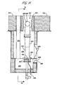
- a burner 10 includes a freestanding burner tube 12 located in a well in a floor 14 of a furnace.
- the burner tube 12 includes an upstream end 16, a downstream end 18 and a venturi 19.
- Burner tip 20 is located at the downstream end 18 of tube 12 and is surrounded by an annular tile 22.
- a fuel orifice 11, which may be located within a gas spud 24, is at the top end of a gas fuel riser 25 and is located at the upstream end 16 of tube 12 and introduces fuel into the burner tube 12.
- Fresh or ambient air is introduced into a primary air chamber 26 through an adjustable damper 28 to mix with the fuel at the upstream end 16 of the burner tube 12 and pass upwardly through the venturi portion 19.
- a motive force is provided by the flow of fuel into venturi portion 19, inducing the flow of flue gas recirculation, air and optionally steam into the burner tube 12.
- one or more steam injection tubes 15 may be provided and positioned in the direction of flow so as to add to the motive force provided by venturi portion 19 for inducing the flow of recirculated flue gas and air into the burner tube 12.
- a plurality of air ports 30 originate in a secondary air chamber 32 and pass through the furnace floor 14 into the furnace. Fresh or ambient air enters the secondary air chamber 32 through adjustable damper 34 and passes through the staged air ports 30 into the furnace to provide secondary or staged combustion, as described in U.S. Patent No. 4,629,413 , which patent is hereby incorporated herein by reference.
- flue gas is drawn from the furnace through passageway 76 into a primary air chamber 26 by the inspirating effect of the fuel from the fuel orifice 11, which may be contained within spud 24, passing through the venturi portion 19.
- Unmixed low temperature fresh or ambient air having entered the secondary air chamber 32 through the dampers 34 and having passed through the air ports 30 into the furnace, is also drawn through passageway 76 into a primary air chamber 26 by the inspirating effect of the fuel passing through the venturi portion 19.
- the passageway 76 is preferably metallic and is employed as an FGR duct. The mixing of the staged or secondary air with the flue gas lowers the temperature of the hot flue gas flowing through the passageway 76 and thereby substantially increases the life of the passageway 76 and allows use of this type burner to reduce NO x emission in high temperature cracking furnaces having flue gas temperature above 1040 °C (1900 °F) in the radiant section of the furnace.
- U.S. Patent No. 5,092,761 contemplates locating a steam injection point(s) at the base of the venturi for the purpose of reducing NO x .
- This is also known as deNO x steam injection.
- means for injecting steam in the form of deNO x , steam injection tube(s) 53 are located in the passageway 76 upstream of the air source 80. This location results in a more homogenous combination of flue gas, steam, air or mixtures thereof and air entering the burner venturi 19. A more homogeneous mixture can result in higher venturi capacity, higher flue gas entrainment capacity, lower flame temperature and lower NO x . This location also tends to reduce the temperature of the metallic FGR duct 76, which extends the life of the duct.
- a lighting port 50 is provided in the burner plenum 48, both to allow inspection of the interior of the burner assembly, and to provide access for lighting of the burner through lighting element (not shown).
- the burner plenum 48 may be covered with mineral wool soundproofing and wire mesh screening to provide insulation therefore.
- a small gap exists between the burner tip 20 and the annular tile 22.
- the bulk of the secondary staged air is forced to enter the furnace through staged air ports 30 located some distance from the primary combustion zone, which is located immediately on the furnace side of the burner tip 20.
- staged air ports 30 located some distance from the primary combustion zone, which is located immediately on the furnace side of the burner tip 20. It has been discovered through testing that increasing the gap between the burner tip 20 and the annular tile 22 raises overall NO x but also raises overall flame stability.
- the annular gap should be sized such that it is small enough to minimize NO x , and large enough to maintain adequate flame stability.
- Flue gas is drawn from near the furnace floor through the passageway 76 by the inspirating effect of fuel passing through venturi portion 19 of burner tube 12. In this manner, the primary air and flue gas are mixed in primary air chamber 26, which is prior to the point of combustion. The amount of inert material mixed with the fuel is raised, thereby reducing the flame temperature, and as a result, reducing NO x emissions.
- Closing or partially closing damper 28 restricts the amount of fresh air that can be drawn into the primary air chamber 26 and thereby provides the vacuum necessary to draw flue gas from the furnace.
- a mixture of from 20% to 80% flue gas and from 20% to 80% ambient air should be drawn through the passageway 76. It is particularly preferred that a mixture of 50% flue gas and 50% ambient air be employed.
- the desired proportions of flue gas and ambient air may be achieved by proper placement and/or design of the passageway 76 in relation to the air ports 30. That is, the geometry of the air ports, including but not limited to their distance from the burner tube, the number of air ports, and the size of the air ports, may be varied to obtain the desired percentages of flue gas and ambient air.
- FIG. 4 illustrates another embodiment of the invention for using steam injection to enhance the flue gas recirculation ratio of a burner 100.
- fuel exits a fuel orifice 111, which may be located within fuel spud 102, at a high velocity at the entrance to a venturi portion 104 of a burner tube 106, thus inspirating air from a primary air chamber 110 into the venturi portion 104.
- Partially closing the primary air dampers 108 generates a sub-ambient pressure in the primary air chamber 110.
- a flue gas recirculation (FGR) duct 112 connects the furnace to the primary air chamber 110 of the burner 100, thus permitting the flow of the flue gas into the primary air chamber 110 to be mixed with fuel from the fuel orifice 111 and primary air from the dampers 108.
- FGR flue gas recirculation
- the flue gas recirculation duct 112 has a venturi section 116. Steam for NO x reduction is injected at the entrance of the venturi section 116 through an orifice, which may be located within spud 120 of steam injection tube 118 for generating a high velocity steam jet at the entrance to venturi section 116.
- the steam jet/venturi combination inspirates flue gas from the floor 122 of the furnace into the primary air chamber 110 of the burner 100.
- the pressure in the primary air chamber 110 does not need to be reduced as far below ambient as does the burner of U.S. Patent No. 5,092,761 , the mixture of flue gas, air and steam is more homogeneous and a greater volume of flue gas can be recycled, providing higher FGR ratios and lower NO x emissions, while still maintaining sufficient primary air flow to assure good burner stability.
- one or more steam injection tubes 115 may be provided and positioned in the direction of flow so as to add to the motive force provided by venturi portion 104 for inducing the flow of flue gas, air and mixtures thereof into the burner tube 106.
- a plurality of staged air ports originates in a secondary air chamber 132 and passes through the furnace floor 122 into the furnace. Fresh or ambient air enters the secondary air chamber 132 through adjustable dampers 135 and passes through the staged air ports (not shown) into the furnace to provide secondary or staged combustion.
- the upper end 66 of burner tip 20 includes a plurality of main ports 64 in a centrally disposed end surface 69 and a plurality of side ports 68 in an annular side surface 67.
- the side ports 68 direct a portion of the fuel/air mixture across the face of the annular tile 22, whereas the main ports 64 direct the major portion of the mixture into the furnace.
- Mating of the lower end of burner tip 20 to the burner tube 12 can be achieved by swaging or, more preferably, by welding or threaded engagement.
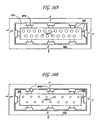
- FIGS. 6A and 6B the upper end 66 of a burner tip in accordance with an embodiment of the present invention is shown in FIG. 6A.
- FIG. 6B shows the upper end 66 of a conventional burner tip. It will be seen that the number and size of the main ports 64 in the centrally disposed end surface 69 of the burner tip in accordance with an embodiment of the present invention are significantly larger than those of the conventional tip.
- the number and dimensions of the main ports 64 in the tip of the invention are such that the total area of the main ports 64 in the end surface 69 is at least 2.2 mm 2 per kilojoules/sec (1.0 in 2 per million (MM) Btu/hr) and preferably at least 2.6 mm 2 per kilojoules/sec (1.2 in 2 per MM Btu/hr) burner capacity.
- the total area of the main ports 64 in the end surface 69 is less than 2.2 mm 2 per kilojoules/sec (1.0 in 2 per million (MM) Btu/hr) burner capacity.
- the total area of the main ports 64 in the end surface 69 is 54.2 cm 2 (8.4 in 2 ) whereas, in the conventional burner tip for use at the same design firing rate, the total area of these openings is only 37.4 cm 2 (5.8 in 2 ).
- Increasing the total area of the main ports 64 in the burner tip 20 increases the flow area of the burner tip 20, which in turn enables higher FGR, rates to be induced without increasing the velocity for the fuel/air mixture flowing through the tip. In this way, stable operation of the burner can be retained with higher FGR rates.
- the venturi 19 of the burner shown in FIG. 13B and discussed below is used in combination with the burner tip feature just discussed.
- the increased flue gas recirculation resulting from the venturi 19 of FIG. 13B reduces the lowering of tip velocity that results with the increased opening area in the tip.
- a longer venturi throat also promotes better flow development and hence improved mixing of the fuel/air stream prior to the mixture exiting the burner tip 20.
- Better mixing of the fuel/air stream also contributes to NO x reduction by producing a more evenly developed flame and hence reducing peak temperature regions.
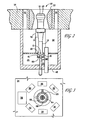
- support members 61 suspend a perforated centering plate 60 from the roof of the primary air chamber 26.
- a specific embodiment of the perforated centering plate 60 has a plurality of spokes 62 interconnecting a riser centering member 63 and a peripheral ring support member 64.
- the riser centering member 63 is positioned about the gas riser 25 for maintaining the fuel spud 24 in proper alignment with the inlet to the venturi portion 19.
- the ring member 64 has a plurality of holes 96 for use in securing the centering plate 60 to the support members 61.
- centering plate 60 also contains a pair of holes 98 to permit a corresponding pair of steam injection tubes 15 to pass through centering plate 60 when such steam injection tubes 15 are present.
- centering plate 60 is perforated to permit flow therethrough of air from the primary air chamber 26, which avoids flow losses that result from a normally tortuous flow pattern caused by a presently used solid centering plate. These flow losses are avoided because the perforated centering plate design smoothes out the flow vectors entering the venturi portion 19 of the burner tube 12 to enable higher venturi capacity, higher flue gas recirculation rate, lower flame temperature and lower NO x production.
- centering plate 60 as shown in FIG. 7 is illustrated as circular and although a circular shape is the preferred embodiment of the present invention, it will be understood by those of skill in the art that the centering plate may be formed into many other shapes, including, for example, oval, square, or triangular without departing from the scope or spirit of the present invention.
- an novel external FGR duct arrangement is now discussed in connection with FIG. 8 .
- flue gas having a temperature less than 370°C (700°F) is drawn from furnace exhaust 300 through an external recirculation (FGR) duct 376 into a primary air chamber 78 by the inspirating effect of the fuel from the fuel orifice 11, which may be located within fuel spud 24, passing through the venturi portion 19.
- FGR external recirculation
- Drawing flue gas from the exhaust stream rather than directly from the furnace box adjacent the burner flame provides a lower temperature flue gas, thereby substantially increasing the effectiveness of the flue gas to lower flame temperature, which results in reduced NO x emissions.
- a further advantage over systems drawing flue gas from the radiant box of the furnace lies in the fact that externally drawn FGR typically has a lower oxygen content. Flue gas sourced externally from the furnace exhaust stack will typically have a 2-3 volume % O 2 content. By comparison, it has been found that flue gas recirculated from the base of the burner flame has a typical O 2 content of 10-15 volume%. Recirculated flue gas with a lower O 2 content is a more effective diluent for reducing NO x because it is less reactive, i.e., more inert.
- FIG. 9 is a schematic illustration of the present invention wherein multiple burners of the types described herein are included in a furnace and share the same FGR duct 376 and furnace exhaust 300.
- primary air may be admitted to burners 310 through primary dampers 328a, through damper(s) 328b or through a combination of primary dampers 328a and damper(s) 328b.
- FIG. 9 shows six burners 310, any number of burners, whether more or less, in series or parallel, may be used and remain within the spirit and scope of the present invention. It will be understood by one of skill in the art that several burners will be located within the furnace, all of which feed furnace exhaust 300 and external FGR duct 376.
- the benefit with respect to improved inspiration produced by the present invention serves to increase the motive force available to draw flue gas through FGR duct 376, eliminating or minimizing the need for an external fan to supply adequate levels of FGR.
- FIG. 10 presents a plot of NO x emissions as a function of external flue gas recirculation level, with varying levels of steam injection. As shown, these results are compared with results obtained using 15% internal FGR. This figure demonstrates the benefits of this aspect of the present invention.
- Fuel spud 24 is affixed to the outlet end of fuel riser 25, preferably by threads, as shown. Fuel spud 24 is aligned with the upstream end 16 of burner tube 12, so that fuel exiting the outlet end 29 of fuel spud 24 will be drawn into the upstream end 16 of burner tube 12, together with primary air and recirculated flue gas. As shown, the inner diameter of the inlet end 23 of fuel spud 24 transitions to a smaller diameter at outlet end 29 through the use of transition section 27.
- the outer surface 21 of fuel spud 24 is exposed to the venturi inlet flow stream, represented by streamlines S. Outer surface 21 is in the form of a hex-shaped nut, for ease in installation.
- outer surface 21 may be helpful in the installation of fuel spud 24, as is illustrated by streamlines S of FIG. 11A , when air is drawn into the venturi inlet 16, flow past the edges of fuel spud 24 generates a zone of eddies and turbulence immediately adjacent to the highest velocity portion of fuel spud 24.
- the energy dissipated in this zone of eddies has been discovered to reduce the inspirating efficiency of the fuel spud 24 and burner tube 12 venturi combination. This inefficiency has been found to limit the FGR ratio achievable in the burner.
- FIG. 11B depicts a fuel spud 124, designed in accordance with one embodiment of the present invention.
- fuel spud 124 employs a smoothly profiled outer surface 121 to eliminate flow separation and eddies as the air and recycled flue-gas pass over fuel spud 124 into upstream end 16 of burner tube 12.
- flow streamlines S' eddies and turbulence are minimized, thus improving the inspirating efficiency of the system.
- higher FGR ratios and lower NOx emissions can be achieved.
- FIG. 11C illustrates another fuel spud 224, designed in accordance another embodiment of the present invention.
- the fuel spud/burner tube venturi combination inspirates air (or air plus flue-gas) via the transfer of momentum from the fuel to the air (or air plus flue-gas) in the burner tube 12 venturi.
- the momentum of a flowing stream is defined as the product of the mass flow rate and velocity.
- the mass flow rate of the fuel stream is defined by the heat release required of the burner.
- the diameter of the fuel spud is established by the available upstream pressure in the fuel gas supply system.
- the momentum achieved in the fuel jet as it exits the fuel spud is a function of the exit velocity.
- the laws of compressible gas flow suggest that the flow at the exit of the fuel spud cannot exceed Mach 1, that is, the speed of sound in the gas stream.
- gas-spuds 224 and 324 are shown, each employing Laval nozzles 227 and 327, respectively. Additionally, fuel spud 324 advantageously employs both the Laval nozzle internal profile 327, and the low-eddy external surface profile 321, described above.
- FIG. 11E depicts a fuel spud 424, designed in accordance with another preferred form.
- fuel spud 424 employs a smoothly profiled outer surface 421, which takes the form of a frustum of a cone, to eliminate flow separation and eddies as the air and recycled flue-gas pass over fuel spud 424 into upstream end 16 of burner tube 12.
- flow streamlines S iv eddies and turbulence are minimized, thus improving the inspirating efficiency of the system.
- higher FGR ratios and lower NO x emissions can be achieved.
- the fuel spud designs of the present invention can be incorporated in new burners or can be retrofitted into existing burners. Unlike prior designs, use of the fuel spud designs of the present invention serve to substantially improve the inspiration characteristics of the fuel spud/burner tube venturi combination, increasing the ability to utilize higher levels of FGR and reduce NO x emissions.
- FIG. 12A illustrates a conventional fuel gas control system 400.
- the fuel pressure 406 upstream of the fuel spuds of burners 450 is controlled by a pressure control valve 410.
- the set-point for the pressure controller is reset by a higher level control application, such as the desired heat release, desired process outlet temperature or the like.
- the fuel supply control system 500 of the present invention shown in FIG.
- the fuel passes through a heat exchanger 518 prior to entering the burners 550.
- the quantity of fuel delivered to the burners 550 is controlled by a flow controller 510 rather than a pressure controller.
- the fuel flow controller 510 may be reset by a higher level controller such as heat release, desired process outlet temperature or the like.
- the temperature to which the fuel is heated is determined by the pressure at the burner inlets to provide optimum spud performance desired.
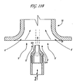
- a venturi 19 of a conventional burner of the type disclosed in U.S. Patent No. 5,092,761 includes a relatively short throat portion 19a that is of substantially constant internal cross-sectional dimensions along its length and a divergent cone portion 19b, wherein the ratio of the length to maximum internal cross-sectional dimension of the throat portion 19a is less than 3, typically 2.6.
- a venturi 19 of a burner tube of a burner in accordance with one embodiment of the invention also includes a throat portion 19a of substantially constant internal cross-sectional dimensions and a divergent cone portion 19b.
- the throat portion 19a of the burner of said one embodiment is significantly longer than that of the conventional burner, as shown in FIG.
- the ratio of the length to maximum internal cross-sectional dimension of the throat portion 19a is at least 3, preferably from 4 to 10, more preferably from 4.5 to 8 still more preferably from 6.5 to 7.5 and most preferably from 6.5 to 7.0.
- the internal surface of the throat portion 19a of the burner of said one embodiment is preferably cylindrical.
- Increasing the ratio of length to internal cross-sectional dimensions in the throat portion of the venturi is found to reduce the degree of flow separation that occurs in the throat and cone portions of the venturi which increases the capacity of the venturi to entrain flue gas thereby allowing higher flue gas recirculation rates and hence reduced flame temperature and NO x production.
- a longer venturi throat also promotes better flow development and hence improved mixing of the fuel gas/air stream prior to the mixture exiting the burner tip. Better mixing of the fuel gas/air stream also contributes to NO x reduction by producing a more evenly developed flame and hence reducing peak temperature regions.
- the cross-section of the FGR duct 76 shown in FIG. 1 is substantially rectangular, typically with its minor dimension ranging from 30% to 100% of its major dimension.
- the cross sectional area of the FGR duct 76 ranges from 11 to 26 mm 2 /kJ/sec (5 to 12 square inches/ million (MM) Btu/hr) burner capacity and, in a practical embodiment, from 219 to 387 cm 2 (34 in 2 to 60 in 2 ).
- the FGR duct 76 can accommodate a mass flow rate of at least 43 g/sec per kilojoules/sec (100 pounds per hour per MMBtu/hr) burner capacity, preferably at least 56 g/sec per kilojoules/sec (130 lbs/hr per MMBtu/hr) burner capacity, and still more preferably at least 86 g/sec per kilojoules/sec (200 lbs/hr per MMBtu/hr) burner capacity.
- FGR ratios of greater than 10% and up to 15% or even up to 20% can be achieved. This arrangement for FGR duct 76 may be applied in combination with the various other teachings and embodiments described herein.
- a burner 410 includes a freestanding burner tube 412 located in a well in a furnace floor 414.
- Burner tube 412 includes an upstream end 416, a downstream end 418 and a venturi portion 419.
- Burner tip 420 is located at downstream end 418 and is surrounded by a peripheral tile 422.
- a fuel orifice 411 which may be located within gas spud 424, is located at upstream end 416 and introduces fuel gas into burner tube 412.
- Fresh or ambient air may be introduced into primary air chamber 426 through dampers 428 to mix with the fuel gas at upstream end 416 of burner tube 412. Combustion of the fuel gas occurs downstream of burner tip 420.
- Fresh secondary air enters secondary chamber 432 through dampers 434.
- a flue gas recirculation passageway 476 is formed in furnace floor 414 and extends to primary air chamber 426, so that flue gas is mixed with fresh air drawn into the primary air chamber from opening 480 through dampers 428. Flue gas is drawn through passageway 476 by the inspirating effect of fuel gas passing through venturi portion 419 of burner tube 412. In this manner, primary air and flue gas are mixed in primary air chamber 426, which is prior to the point of combustion. Therefore, the amount of inert material mixed with the fuel is raised, thereby reducing the flame temperature.
- one or more steam injection tubes 484 may be provided and positioned in the direction of flow so as to add to the motive force provided by venturi portion 419 for inducing the flow of recirculated flue gas and air into the burner tube 412.
- a small gap exists between the burner tip 120 and the burner tile 122.
- the bulk of the secondary staged air is forced to enter the furnace through staged air ports (not shown) located some distance from the primary combustion zone, which is located immediately on the furnace side of the burner tip 120.
- This gap may be peripheral in configuration, as shown, or alternatively, comprise a series of spaced gaps peripherally arranged.
- This example explores the advantages of a burner of the type depicted in FIG. 4 , as modeled based on material balance calculations.
- the fuel orifice/fuel spud is preferably of the type disclosed herein in connection with FIGS. 11A-11E .
- a total of 415 kg/hr (914 lb/hr) of air is drawn into the primary air chamber 110.
- Steam is injected at a rate of 54 kg/hr (120 lb/hr) through the steam injection tube 118, and the steam pressure upstream of the orifice 120 may be in the range 240-790 kPa (20-100 psig) to generate a high velocity steam jet.
- a suitable typical pressure may be 377 kPa (40 psig).
- the action of the high velocity steam jet in the FGR venturi section 116 would inspirate approximately 360 kg/hr (800 lb/hr) of flue gas into the FGR duct 112, providing an FGR ratio of approximately 15%.
- the embodiments of the instant invention are designed to generate FGR ratios in the range 10-25%.
- a burner of the type depicted in FIG. 4 was tested.
- the fuel orifice/fuel spud was the type disclosed in FIG. 11E .
- the burner of this example also employed flue gas recirculation as described herein and was operated at a firing rate of 1760 kJ/sec (6 MMBTU/hr), using a fuel gas comprised of 30% H 2 /70% natural gas, without steam injection. A very stable flame was observed, with NO x emissions measured at 67 ppm.
- Example 2 the burner of Example 2 was used.
- the burner employed flue gas recirculation as described herein and was operated at a firing rate of 1760 kJ/sec (6 million BTU/hr), using a fuel gas comprised of 30% H 2 /70% natural gas, with steam injected to the FGR duct (only) at a rate of 65 kg/hr (143 lb/hr). A very stable flame was observed, with NO x emissions measured at 42 ppm.
- Example 2 the burner of Example 2 was used, employing flue gas recirculation of the type described herein.
- the burner was operated at a firing rate of 1760 kJ/sec (6 MMBTU/hr), using a fuel gas comprised of 30% H 2 /70% natural gas, with steam injected in the region of the burner tube venturi (only) at a rate of 65 kg/hr (143 lb./hr). A very stable flame was observed, with NO x emissions measured at 37 ppm.
- Fueling rate for the optimized nozzle of Example 5 was reduced to 106 kg/hr (233 lb./hr.), while using the same fuel (CH 4 ) and maintaining fuel upstream temperature at 21 °C.(60 °F), fuel upstream pressure at 297 kPa (28.4 psig), spud throat diameter at 0.85 cm (0.3360 in).
- Example 6 To take the optimum nozzle design for the conditions of Example 6 and increase the firing rate to the level of Example 5 (158 kg/hr (348 lb./hr.)) would be predicted to yield the following results: Nozzle Exhaust Diameter Gas Pressure at Nozzle Exit Gas velocity at Nozzle Exit 0.90 cm (0.3534 in) 62.44 kPa(7.0 psig) 1938 km/hr (1,766 ft/sec)
- the fueling rate for the optimized nozzle of Example 5 was reduced to 106 kg/hr (233 lb/hr), while using the same fuel (CH 4 ) and increasing the fuel upstream temperature to 377 °C (710 °F). Fuel upstream pressure was maintained at 446 kPa (50 psig) and spud throat diameter was held at 0.85 cm (0.3360 in).
- Table 1 summarizes the geometry of a conventional premix burner with FGR (Example 9) and five premix burners (Examples 10-14) having modified venturi throat portions.
- Table 1 Example Venturi Inlet Radius cm (in) Venturi Throat Int. Dia.
- the length/diameter ratio of the venturi throat portion should preferably not exceed 10, more preferably is between 6.5 and 7.5 and most preferably is between 6.5 and 7.0.
- CFD was used to evaluate the configurations described below.
- a CFD analysis solves fundamental controlling equations and provides fluid velocity, species, combustion reactions, pressure, heat transfer and temperature values, etc. at every point in the solution domain.
- FLUENTTM software from Fluent Inc. was used to perform the analysis.
- the present invention can be incorporated in new burners or can be retrofitted into existing burners by alterations to the burner surround.
- burners of this invention have been described in connection with floor-fired hydrocarbon cracking furnaces, they may also be used in furnaces for carrying out other reactions or functions.
Landscapes
- Engineering & Computer Science (AREA)
- Chemical & Material Sciences (AREA)
- Combustion & Propulsion (AREA)
- Mechanical Engineering (AREA)
- General Engineering & Computer Science (AREA)
- Gas Burners (AREA)
Claims (20)
- Brenner (10) zur Verbrennung von Brennstoff in einem Ofen, wobei der Brenner aufweist:(a) eine Primärluftkammer (26),(b) ein Brennerrohr (12) mit einem Eingangsende (16), einem Ausgangsende (18) und einer Venturidüse (19) zwischen dem Eingangs- und dem Ausgangsende, wobei die Venturidüse einen Halsbereich (19a) mit einem im Wesentlichen konstanten inneren Querschnittsmaß einschließt, sodass das Verhältnis der Länge zum höchsten inneren Querschnittsmaß des Halsbereichs mindestens 3 beträgt,(c) einen Brennstoffstutzen (24), der sich neben dem Eingangsende des Brennerrohrs befindet, zum Einbringen von Brennstoff in das Brennerrohr,(d) eine Brennerspitze (20), die an dem Ausgangsende des Brennerrohrs neben einer ersten Öffnung in dem Ofen befestigt ist,(e) mindestens einen Durchgang (76) mit einem ersten Ende und einem zweiten Ende neben dem Eingangsende des Brennerrohrs und(f) Mittel zum Abziehen von Abgas aus dem Ofen, durch mindestens einen Durchgang, als Reaktion auf eine Mitreißwirkung von unverbranntem Brennstoff, der aus dem Brennstoffstutzen austritt, wobei der unverbrannte Brennstoff durch das Brennerrohr von dessen Eingangsende zu dessen Ausgangsende strömt,
wobei der Brennstoffstutzen Mittel zum Erhöhen der Mitreißwirkung von unverbranntem Brennstoff, der aus dem Brennstoffstutzen austritt, einschließt, und ferner eine Zentrierplatte (60) zum Zentrieren des Brennstoffstutzens, mit dem Brennerrohr ausgerichtet, aufweist, dadurch gekennzeichnet, dass die Zentrierplatte perforiert ist, um eine Strömung durch sie hindurch aus der Primärluftkammer zu ermöglichen. - Brenner nach Anspruch 1, wobei das Verhältnis der Länge zum höchsten inneren Querschnittsmaß des Halsbereichs 4 bis 10 beträgt.
- Brenner nach Anspruch 1 oder Anspruch 2, der ferner ein oder mehrere Dampfrohre aufweist, die neben dem Eingangsende des Brennerrohrs enden, zum Einbringen von Dampf zusammen mit Luft und dem Brennstoff in das Brennerrohr.
- Brenner nach einem der vorhergehenden Ansprüche, wobei mindestens einer der Durchgänge einen Durchgang einschließt, der in dem Brenner innen ist.
- Brenner nach Anspruch 1, Anspruch 2 oder Anspruch 3, wobei der mindestens eine Durchgang zumindest teilweise außerhalb des Ofens ist und sich in Fluidkommunikation mit einer Mehrzahl von Brennern in dem Ofen befindet.
- Brenner nach einem der vorhergehenden Ansprüche, wobei das Mittel zum Abziehen von Abgas ferner eine erste einstellbare Dämpferöffnung in Fluidkommunikation mit der Primärluftkammer und einer Quelle für Luft aufweist.
- Brenner nach Anspruch 6, der ferner eine Sekundärluftkammer und eine zweite einstellbare Dämpferöffnung in die Sekundärluftkammer aufweist, um die Menge an Luft zu begrenzen, die in die Sekundärluftkammer eintritt, wobei die Sekundärluftkammer in Fluidkommunikation mit mindestens einer Luftöffnung in den Ofen steht.
- Brenner nach Anspruch 7, der ferner mindestens einen Luftanschluss in Fluidkommunikation mit der Sekundärluftkammer besitzt.
- Brenner nach Anspruch 1, wobei die Zentrierplatte ein äußeres Ringelement, ein inneres Zentrierelement und eine Mehrzahl von sich nach außen erstreckenden Speichen aufweist, die das äußere Ringelement und das innere Zentrierelement verbinden.
- Brenner nach Anspruch 9, wobei das äußere Ringelement die Zentrierplatte in der Primärluftkammer sicher befestigt, und wobei sich ein Gassteigrohr durch das innere Zentrierelement erstreckt und davon gehalten wird.
- Brenner nach einem der vorhergehenden Ansprüche, der ferner Mittel zum Einbringen von Dampf in die Primärluftkammer aufweist.
- Brenner nach einem der vorhergehenden Ansprüche, wobei der Brenner ein Vormischbrenner ist.
- Brenner nach einem der vorhergehenden Ansprüche, wobei der Brenner ein Flachflammenbrenner ist.
- Brenner nach einem der vorhergehenden Ansprüche, wobei der Brennstoff ein Brennstoffgas ist.
- Brenner nach einem der vorhergehenden Ansprüche, wobei das Mittel zum Erhöhen der Mitreißwirkung von unverbranntem Brennstoff, der aus dem Brennstoffstutzen austritt, eine im Profil glatte äußere Oberfläche des Brennstoffstutzens ist, wobei die äußere Oberfläche in der Lage ist, Strömungstrennung und Strömungswirbel zu vermindern, während Luft und Abgas über den Brennstoffstutzen in das Eingangsende des Brennstoffrohrs geleitet werden.
- Brenner nach einem der vorhergehenden Ansprüche, wobei das Mittel zum Erhöhen der Mitreißwirkung von unverbranntem Brennstoff, der an dem Brennstoffstutzen austritt, eine zusammenlaufende/auseinanderlaufende Laval-Düse einschließen, die in dem Brennstoffstutzen gebildet ist.
- Brenner nach Anspruch 16, der ferner ein Brennstoffzufuhrkontrollsystem aufweist, wobei das Brennstoffzufuhrkontrollsystem einen Heizer zum Erhitzen des Brennstoffs vor dem Eintreten in den Brenner auf eine Temperatur einschließt, die wirksam ist, um die Geschwindigkeit des aus der Laval-Düse des Brennstoffstutzens austretenden Brennstoffs zu maximieren.
- Brenner nach einem der vorhergehenden Ansprüche, wobei die Brennerspitze eine Mehrzahl von Zentralbrennerspitzenöffnungen in dessen äußerer Oberfläche umfasst, sodass die Verbrennung des Brennstoffs stromabwärts von der äußeren Oberfläche der Brennerspitze stattfindet, wobei die Zahl und Maße der Zentralbrennerspitzenöffnungen in der äußeren Oberfläche so sind, dass das Verhältnis der Gesamtfläche der Zentralbrennerspitzenöffnungen in der äußeren Oberfläche mindestens 2,2 mm2 je Joule/Sekunde (1 Quadratzoll je Millionen (MM) Btu/h) Brennerkapazität beträgt.
- Brenner nach einem der vorhergehenden Ansprüche, wobei die Querschnittsfläche des Durchgangs ein größeres Maß und ein geringeres Maß im Bereich von 30 % bis 100 % des größeren Maßes besitzt.
- Brenner nach einem der vorhergehenden Ansprüche, der ferner mindestens ein Dampfrohr zum Einbringen von Dampf in den Durchgang stromaufwärts von der Quelle für Luft besitzt.
Applications Claiming Priority (15)
| Application Number | Priority Date | Filing Date | Title |
|---|---|---|---|
| US36522702P | 2002-03-16 | 2002-03-16 | |
| US36523502P | 2002-03-16 | 2002-03-16 | |
| US36515102P | 2002-03-16 | 2002-03-16 | |
| US36522602P | 2002-03-16 | 2002-03-16 | |
| US36523402P | 2002-03-16 | 2002-03-16 | |
| US36521802P | 2002-03-16 | 2002-03-16 | |
| US36513802P | 2002-03-16 | 2002-03-16 | |
| US365226P | 2002-03-16 | ||
| US365218P | 2002-03-16 | ||
| US365227P | 2002-03-16 | ||
| US365234P | 2002-03-16 | ||
| US365235P | 2002-03-16 | ||
| US365151P | 2002-03-16 | ||
| US365138P | 2002-03-16 | ||
| PCT/US2003/007906 WO2003081131A1 (en) | 2002-03-16 | 2003-03-14 | Burner system with improved flue gas recirculation |
Publications (2)
| Publication Number | Publication Date |
|---|---|
| EP1495262A1 EP1495262A1 (de) | 2005-01-12 |
| EP1495262B1 true EP1495262B1 (de) | 2015-04-15 |
Family
ID=28458096
Family Applications (1)
| Application Number | Title | Priority Date | Filing Date |
|---|---|---|---|
| EP03744726.5A Expired - Lifetime EP1495262B1 (de) | 2002-03-16 | 2003-03-14 | Brennersystem mit verbesserter rauchgasrückführung |
Country Status (4)
| Country | Link |
|---|---|
| EP (1) | EP1495262B1 (de) |
| JP (1) | JP4264003B2 (de) |
| AU (1) | AU2003225801A1 (de) |
| WO (1) | WO2003081131A1 (de) |
Cited By (2)
| Publication number | Priority date | Publication date | Assignee | Title |
|---|---|---|---|---|
| WO2018093490A1 (en) * | 2016-11-15 | 2018-05-24 | Honeywell International Inc. | Burner for a furnace and a method of assembly |
| EP3784758A1 (de) * | 2018-04-26 | 2021-03-03 | Technip France | Brennersystem für einen dampfcrackofen |
Families Citing this family (3)
| Publication number | Priority date | Publication date | Assignee | Title |
|---|---|---|---|---|
| JP5216369B2 (ja) * | 2008-02-29 | 2013-06-19 | 電源開発株式会社 | バーナおよびその運転方法 |
| EP3910236B1 (de) * | 2020-05-15 | 2024-04-03 | L'air Liquide, Société Anonyme Pour L'Étude Et L'exploitation Des Procédés Georges Claude | Prozessbrenner und verfahren zur verbrennung kohlenmonoxidhaltiger brenngase |
| US20230213181A1 (en) * | 2021-12-31 | 2023-07-06 | Honeywell International Inc. | Low nox gas burner with cooled flue gas recycle |
Family Cites Families (6)
| Publication number | Priority date | Publication date | Assignee | Title |
|---|---|---|---|---|
| US2813578A (en) * | 1954-02-08 | 1957-11-19 | Nat Airoil Burner Company Inc | Burners |
| US2983312A (en) * | 1959-05-20 | 1961-05-09 | Finco Inc | Gas burner |
| DE3842842A1 (de) * | 1988-12-20 | 1990-06-21 | Zink John Gmbh | Atmosphaerischer brenner |
| US5098282A (en) * | 1990-09-07 | 1992-03-24 | John Zink Company | Methods and apparatus for burning fuel with low NOx formation |
| US5092761A (en) * | 1990-11-19 | 1992-03-03 | Exxon Chemical Patents Inc. | Flue gas recirculation for NOx reduction in premix burners |
| US5472341A (en) * | 1994-06-01 | 1995-12-05 | Meeks; Thomas | Burner having low pollutant emissions |
-
2003
- 2003-03-14 AU AU2003225801A patent/AU2003225801A1/en not_active Abandoned
- 2003-03-14 JP JP2003578822A patent/JP4264003B2/ja not_active Expired - Fee Related
- 2003-03-14 WO PCT/US2003/007906 patent/WO2003081131A1/en not_active Ceased
- 2003-03-14 EP EP03744726.5A patent/EP1495262B1/de not_active Expired - Lifetime
Cited By (6)
| Publication number | Priority date | Publication date | Assignee | Title |
|---|---|---|---|---|
| WO2018093490A1 (en) * | 2016-11-15 | 2018-05-24 | Honeywell International Inc. | Burner for a furnace and a method of assembly |
| CN109923347A (zh) * | 2016-11-15 | 2019-06-21 | 霍尼韦尔国际公司 | 用于炉的燃烧器和组装方法 |
| US10690339B2 (en) | 2016-11-15 | 2020-06-23 | Honeywell International Inc. | Burner for a furnace and a method of assembly |
| EP3784758A1 (de) * | 2018-04-26 | 2021-03-03 | Technip France | Brennersystem für einen dampfcrackofen |
| US12117169B2 (en) | 2018-04-26 | 2024-10-15 | Technip France | Burner system for a steam cracking furnace |
| EP3784758B1 (de) * | 2018-04-26 | 2025-11-05 | Technip Energies France | Brennersystem für einen dampf-crackofen |
Also Published As
| Publication number | Publication date |
|---|---|
| AU2003225801A1 (en) | 2003-10-08 |
| WO2003081131A1 (en) | 2003-10-02 |
| EP1495262A1 (de) | 2005-01-12 |
| JP2005521023A (ja) | 2005-07-14 |
| JP4264003B2 (ja) | 2009-05-13 |
Similar Documents
| Publication | Publication Date | Title |
|---|---|---|
| EP1495263B1 (de) | Verbesserter brenner mit niedrigen nox-emissionen | |
| US4629413A (en) | Low NOx premix burner | |
| US6893251B2 (en) | Burner design for reduced NOx emissions | |
| US8454349B2 (en) | Removable light-off port plug for use in burners | |
| US6902390B2 (en) | Burner tip for pre-mix burners | |
| US7025587B2 (en) | Burner with high capacity venturi | |
| US6890172B2 (en) | Burner with flue gas recirculation | |
| US6893252B2 (en) | Fuel spud for high temperature burners | |
| US6846175B2 (en) | Burner employing flue-gas recirculation system | |
| US6866502B2 (en) | Burner system employing flue gas recirculation | |
| US20030175637A1 (en) | Burner employing cooled flue gas recirculation | |
| EP1495262B1 (de) | Brennersystem mit verbesserter rauchgasrückführung | |
| US20030175635A1 (en) | Burner employing flue-gas recirculation system with enlarged circulation duct | |
| US6986658B2 (en) | Burner employing steam injection | |
| US6884062B2 (en) | Burner design for achieving higher rates of flue gas recirculation | |
| US6887068B2 (en) | Centering plate for burner | |
| US20030175634A1 (en) | Burner with high flow area tip | |
| EP1488170B1 (de) | Brenner mit verbessertem abgasrückführungskanal | |
| EP1488171B1 (de) | Brennerausbildung mit höheren abgasrückführverhältnissen und reduzierter nox-emission | |
| WO2003081135A1 (en) | BURNER DESIGN WITH HIGHER RATES OF FLUE GAS RECIRCULATION AND REDUCED NOx EMISSIONS |
Legal Events
| Date | Code | Title | Description |
|---|---|---|---|
| PUAI | Public reference made under article 153(3) epc to a published international application that has entered the european phase |
Free format text: ORIGINAL CODE: 0009012 |
|
| 17P | Request for examination filed |
Effective date: 20041015 |
|
| AK | Designated contracting states |
Kind code of ref document: A1 Designated state(s): AT BE BG CH CY CZ DE DK EE ES FI FR GB GR HU IE IT LI LU MC NL PT RO SE SI SK TR |
|
| AX | Request for extension of the european patent |
Extension state: AL LT LV MK |
|
| 17Q | First examination report despatched |
Effective date: 20091019 |
|
| RIC1 | Information provided on ipc code assigned before grant |
Ipc: F23L 7/00 20060101ALI20140703BHEP Ipc: F23D 14/08 20060101ALI20140703BHEP Ipc: F23M 5/02 20060101ALI20140703BHEP Ipc: F23D 14/58 20060101ALI20140703BHEP Ipc: F23C 7/00 20060101ALI20140703BHEP Ipc: F23C 6/04 20060101ALI20140703BHEP Ipc: F23M 11/04 20060101ALI20140703BHEP Ipc: F23C 9/00 20060101ALI20140703BHEP Ipc: F23D 14/66 20060101ALI20140703BHEP Ipc: F23D 14/04 20060101AFI20140703BHEP |
|
| GRAP | Despatch of communication of intention to grant a patent |
Free format text: ORIGINAL CODE: EPIDOSNIGR1 |
|
| INTG | Intention to grant announced |
Effective date: 20140912 |
|
| GRAJ | Information related to disapproval of communication of intention to grant by the applicant or resumption of examination proceedings by the epo deleted |
Free format text: ORIGINAL CODE: EPIDOSDIGR1 |
|
| GRAP | Despatch of communication of intention to grant a patent |
Free format text: ORIGINAL CODE: EPIDOSNIGR1 |
|
| GRAJ | Information related to disapproval of communication of intention to grant by the applicant or resumption of examination proceedings by the epo deleted |
Free format text: ORIGINAL CODE: EPIDOSDIGR1 |
|
| GRAP | Despatch of communication of intention to grant a patent |
Free format text: ORIGINAL CODE: EPIDOSNIGR1 |
|
| GRAJ | Information related to disapproval of communication of intention to grant by the applicant or resumption of examination proceedings by the epo deleted |
Free format text: ORIGINAL CODE: EPIDOSDIGR1 |
|
| INTG | Intention to grant announced |
Effective date: 20141016 |
|
| GRAP | Despatch of communication of intention to grant a patent |
Free format text: ORIGINAL CODE: EPIDOSNIGR1 |
|
| INTG | Intention to grant announced |
Effective date: 20141029 |
|
| INTG | Intention to grant announced |
Effective date: 20141113 |
|
| GRAS | Grant fee paid |
Free format text: ORIGINAL CODE: EPIDOSNIGR3 |
|
| GRAA | (expected) grant |
Free format text: ORIGINAL CODE: 0009210 |
|
| AK | Designated contracting states |
Kind code of ref document: B1 Designated state(s): AT BE BG CH CY CZ DE DK EE ES FI FR GB GR HU IE IT LI LU MC NL PT RO SE SI SK TR |
|
| REG | Reference to a national code |
Ref country code: GB Ref legal event code: FG4D Ref country code: CH Ref legal event code: EP |
|
| REG | Reference to a national code |
Ref country code: IE Ref legal event code: FG4D |
|
| REG | Reference to a national code |
Ref country code: AT Ref legal event code: REF Ref document number: 722208 Country of ref document: AT Kind code of ref document: T Effective date: 20150515 |
|
| REG | Reference to a national code |
Ref country code: DE Ref legal event code: R096 Ref document number: 60347512 Country of ref document: DE Effective date: 20150528 |
|
| REG | Reference to a national code |
Ref country code: SE Ref legal event code: TRGR |
|
| REG | Reference to a national code |
Ref country code: NL Ref legal event code: T3 |
|
| REG | Reference to a national code |
Ref country code: AT Ref legal event code: MK05 Ref document number: 722208 Country of ref document: AT Kind code of ref document: T Effective date: 20150415 |
|
| PG25 | Lapsed in a contracting state [announced via postgrant information from national office to epo] |
Ref country code: PT Free format text: LAPSE BECAUSE OF FAILURE TO SUBMIT A TRANSLATION OF THE DESCRIPTION OR TO PAY THE FEE WITHIN THE PRESCRIBED TIME-LIMIT Effective date: 20150817 Ref country code: FI Free format text: LAPSE BECAUSE OF FAILURE TO SUBMIT A TRANSLATION OF THE DESCRIPTION OR TO PAY THE FEE WITHIN THE PRESCRIBED TIME-LIMIT Effective date: 20150415 Ref country code: ES Free format text: LAPSE BECAUSE OF FAILURE TO SUBMIT A TRANSLATION OF THE DESCRIPTION OR TO PAY THE FEE WITHIN THE PRESCRIBED TIME-LIMIT Effective date: 20150415 |
|
| PG25 | Lapsed in a contracting state [announced via postgrant information from national office to epo] |
Ref country code: AT Free format text: LAPSE BECAUSE OF FAILURE TO SUBMIT A TRANSLATION OF THE DESCRIPTION OR TO PAY THE FEE WITHIN THE PRESCRIBED TIME-LIMIT Effective date: 20150415 Ref country code: GR Free format text: LAPSE BECAUSE OF FAILURE TO SUBMIT A TRANSLATION OF THE DESCRIPTION OR TO PAY THE FEE WITHIN THE PRESCRIBED TIME-LIMIT Effective date: 20150716 |
|
| REG | Reference to a national code |
Ref country code: DE Ref legal event code: R097 Ref document number: 60347512 Country of ref document: DE |
|
| PG25 | Lapsed in a contracting state [announced via postgrant information from national office to epo] |
Ref country code: EE Free format text: LAPSE BECAUSE OF FAILURE TO SUBMIT A TRANSLATION OF THE DESCRIPTION OR TO PAY THE FEE WITHIN THE PRESCRIBED TIME-LIMIT Effective date: 20150415 Ref country code: DK Free format text: LAPSE BECAUSE OF FAILURE TO SUBMIT A TRANSLATION OF THE DESCRIPTION OR TO PAY THE FEE WITHIN THE PRESCRIBED TIME-LIMIT Effective date: 20150415 |
|
| PLBE | No opposition filed within time limit |
Free format text: ORIGINAL CODE: 0009261 |
|
| STAA | Information on the status of an ep patent application or granted ep patent |
Free format text: STATUS: NO OPPOSITION FILED WITHIN TIME LIMIT |
|
| PG25 | Lapsed in a contracting state [announced via postgrant information from national office to epo] |
Ref country code: CZ Free format text: LAPSE BECAUSE OF FAILURE TO SUBMIT A TRANSLATION OF THE DESCRIPTION OR TO PAY THE FEE WITHIN THE PRESCRIBED TIME-LIMIT Effective date: 20150415 Ref country code: SK Free format text: LAPSE BECAUSE OF FAILURE TO SUBMIT A TRANSLATION OF THE DESCRIPTION OR TO PAY THE FEE WITHIN THE PRESCRIBED TIME-LIMIT Effective date: 20150415 Ref country code: RO Free format text: LAPSE BECAUSE OF NON-PAYMENT OF DUE FEES Effective date: 20150415 |
|
| 26N | No opposition filed |
Effective date: 20160118 |
|
| PG25 | Lapsed in a contracting state [announced via postgrant information from national office to epo] |
Ref country code: IT Free format text: LAPSE BECAUSE OF FAILURE TO SUBMIT A TRANSLATION OF THE DESCRIPTION OR TO PAY THE FEE WITHIN THE PRESCRIBED TIME-LIMIT Effective date: 20150415 |
|
| PG25 | Lapsed in a contracting state [announced via postgrant information from national office to epo] |
Ref country code: SI Free format text: LAPSE BECAUSE OF FAILURE TO SUBMIT A TRANSLATION OF THE DESCRIPTION OR TO PAY THE FEE WITHIN THE PRESCRIBED TIME-LIMIT Effective date: 20150415 |
|
| REG | Reference to a national code |
Ref country code: DE Ref legal event code: R119 Ref document number: 60347512 Country of ref document: DE |
|
| PG25 | Lapsed in a contracting state [announced via postgrant information from national office to epo] |
Ref country code: MC Free format text: LAPSE BECAUSE OF FAILURE TO SUBMIT A TRANSLATION OF THE DESCRIPTION OR TO PAY THE FEE WITHIN THE PRESCRIBED TIME-LIMIT Effective date: 20150415 |
|
| REG | Reference to a national code |
Ref country code: CH Ref legal event code: PL |
|
| REG | Reference to a national code |
Ref country code: NL Ref legal event code: MM Effective date: 20160401 |
|
| REG | Reference to a national code |
Ref country code: IE Ref legal event code: MM4A |
|
| REG | Reference to a national code |
Ref country code: FR Ref legal event code: ST Effective date: 20161130 |
|
| PG25 | Lapsed in a contracting state [announced via postgrant information from national office to epo] |
Ref country code: DE Free format text: LAPSE BECAUSE OF NON-PAYMENT OF DUE FEES Effective date: 20161001 Ref country code: FR Free format text: LAPSE BECAUSE OF NON-PAYMENT OF DUE FEES Effective date: 20160331 Ref country code: IE Free format text: LAPSE BECAUSE OF NON-PAYMENT OF DUE FEES Effective date: 20160314 Ref country code: NL Free format text: LAPSE BECAUSE OF NON-PAYMENT OF DUE FEES Effective date: 20160401 Ref country code: LI Free format text: LAPSE BECAUSE OF NON-PAYMENT OF DUE FEES Effective date: 20160331 Ref country code: CH Free format text: LAPSE BECAUSE OF NON-PAYMENT OF DUE FEES Effective date: 20160331 |
|
| PG25 | Lapsed in a contracting state [announced via postgrant information from national office to epo] |
Ref country code: HU Free format text: LAPSE BECAUSE OF FAILURE TO SUBMIT A TRANSLATION OF THE DESCRIPTION OR TO PAY THE FEE WITHIN THE PRESCRIBED TIME-LIMIT; INVALID AB INITIO Effective date: 20030314 Ref country code: CY Free format text: LAPSE BECAUSE OF FAILURE TO SUBMIT A TRANSLATION OF THE DESCRIPTION OR TO PAY THE FEE WITHIN THE PRESCRIBED TIME-LIMIT Effective date: 20150415 |
|
| PG25 | Lapsed in a contracting state [announced via postgrant information from national office to epo] |
Ref country code: TR Free format text: LAPSE BECAUSE OF FAILURE TO SUBMIT A TRANSLATION OF THE DESCRIPTION OR TO PAY THE FEE WITHIN THE PRESCRIBED TIME-LIMIT Effective date: 20150415 |
|
| PG25 | Lapsed in a contracting state [announced via postgrant information from national office to epo] |
Ref country code: BG Free format text: LAPSE BECAUSE OF FAILURE TO SUBMIT A TRANSLATION OF THE DESCRIPTION OR TO PAY THE FEE WITHIN THE PRESCRIBED TIME-LIMIT Effective date: 20150415 |
|
| PGFP | Annual fee paid to national office [announced via postgrant information from national office to epo] |
Ref country code: LU Payment date: 20191230 Year of fee payment: 18 |
|
| PGFP | Annual fee paid to national office [announced via postgrant information from national office to epo] |
Ref country code: GB Payment date: 20200228 Year of fee payment: 18 Ref country code: SE Payment date: 20200309 Year of fee payment: 18 |
|
| PGFP | Annual fee paid to national office [announced via postgrant information from national office to epo] |
Ref country code: BE Payment date: 20200218 Year of fee payment: 18 |
|
| GBPC | Gb: european patent ceased through non-payment of renewal fee |
Effective date: 20210314 |
|
| REG | Reference to a national code |
Ref country code: BE Ref legal event code: MM Effective date: 20210331 |
|
| PG25 | Lapsed in a contracting state [announced via postgrant information from national office to epo] |
Ref country code: LU Free format text: LAPSE BECAUSE OF NON-PAYMENT OF DUE FEES Effective date: 20210314 Ref country code: SE Free format text: LAPSE BECAUSE OF NON-PAYMENT OF DUE FEES Effective date: 20210315 Ref country code: GB Free format text: LAPSE BECAUSE OF NON-PAYMENT OF DUE FEES Effective date: 20210314 |
|
| PG25 | Lapsed in a contracting state [announced via postgrant information from national office to epo] |
Ref country code: BE Free format text: LAPSE BECAUSE OF NON-PAYMENT OF DUE FEES Effective date: 20210331 |