EP1495515B1 - Incorporated power line cable and filter, particularly for appliances - Google Patents
Incorporated power line cable and filter, particularly for appliances Download PDFInfo
- Publication number
- EP1495515B1 EP1495515B1 EP03727303A EP03727303A EP1495515B1 EP 1495515 B1 EP1495515 B1 EP 1495515B1 EP 03727303 A EP03727303 A EP 03727303A EP 03727303 A EP03727303 A EP 03727303A EP 1495515 B1 EP1495515 B1 EP 1495515B1
- Authority
- EP
- European Patent Office
- Prior art keywords
- plate
- power line
- box structure
- hole
- connector
- Prior art date
- Legal status (The legal status is an assumption and is not a legal conclusion. Google has not performed a legal analysis and makes no representation as to the accuracy of the status listed.)
- Expired - Lifetime
Links
Images



Classifications
-
- H—ELECTRICITY
- H01—ELECTRIC ELEMENTS
- H01R—ELECTRICALLY-CONDUCTIVE CONNECTIONS; STRUCTURAL ASSOCIATIONS OF A PLURALITY OF MUTUALLY-INSULATED ELECTRICAL CONNECTING ELEMENTS; COUPLING DEVICES; CURRENT COLLECTORS
- H01R13/00—Details of coupling devices of the kinds covered by groups H01R12/70 or H01R24/00 - H01R33/00
- H01R13/66—Structural association with built-in electrical component
- H01R13/719—Structural association with built-in electrical component specially adapted for high frequency, e.g. with filters
-
- H—ELECTRICITY
- H01—ELECTRIC ELEMENTS
- H01R—ELECTRICALLY-CONDUCTIVE CONNECTIONS; STRUCTURAL ASSOCIATIONS OF A PLURALITY OF MUTUALLY-INSULATED ELECTRICAL CONNECTING ELEMENTS; COUPLING DEVICES; CURRENT COLLECTORS
- H01R13/00—Details of coupling devices of the kinds covered by groups H01R12/70 or H01R24/00 - H01R33/00
- H01R13/73—Means for mounting coupling parts to apparatus or structures, e.g. to a wall
- H01R13/74—Means for mounting coupling parts in openings of a panel
- H01R13/741—Means for mounting coupling parts in openings of a panel using snap fastening means
- H01R13/745—Means for mounting coupling parts in openings of a panel using snap fastening means separate from the housing
-
- H—ELECTRICITY
- H01—ELECTRIC ELEMENTS
- H01R—ELECTRICALLY-CONDUCTIVE CONNECTIONS; STRUCTURAL ASSOCIATIONS OF A PLURALITY OF MUTUALLY-INSULATED ELECTRICAL CONNECTING ELEMENTS; COUPLING DEVICES; CURRENT COLLECTORS
- H01R13/00—Details of coupling devices of the kinds covered by groups H01R12/70 or H01R24/00 - H01R33/00
- H01R13/46—Bases; Cases
- H01R13/50—Bases; Cases formed as an integral body
Definitions
- the present invention relates to a new constructive solution of the connection for the power supply of appliances and their specific devices, in particular for the integration with radio-frequency interference filters or devices.
- the invention relates particularly to an integrated power line cord and circuit assembly for a device such as an appliance having a side wall or casing, said assembly comprising a supplying electric cable and an electric circuit, in particular a radio frequency interference filter.
- a device such as an appliance having a side wall or casing
- said assembly comprising a supplying electric cable and an electric circuit, in particular a radio frequency interference filter.
- a first innovating feature of this invention is that of providing the end of the appliance power cable with a plate over moulded together with the end of the feeding cable itself, said plate intended to be housed in a hole of the steel sheet or casing of the appliance, the inner surface of this plate being able to be linked by coupling both to a supporting element that holds the e.g. radio frequency interference device and to its wires and electric connections necessary for the working of the appliance and said supporting element being embedded in a box structure that closes and protects the above mentioned parts, assuring their ruggedness according also to the electric connection safety standards.
- a supporting element that holds the e.g. radio frequency interference device and to its wires and electric connections necessary for the working of the appliance and said supporting element being embedded in a box structure that closes and protects the above mentioned parts, assuring their ruggedness according also to the electric connection safety standards.
- an integrated connector block-filter group comprising a central body with a hollow that houses the integrated and assembled components of an radio frequency interference filter (RFI filter), while a series of electric contacts are placed on a lateral bracket linked to the main body, to which also a mechanic cable blocking system is applied.
- RFID filter radio frequency interference filter
- the necessity of blocking the power cord with a cable clamp to be applied at the mouth of the connector-filter group does not allow to set in time the power cord connections with the electric contacts set in the same group, binding the installator to carry out these connections on each device, only after the introduction and the fixing of the line cable, which brings to a great discomfort during the working, besides discomforts and additional time to fix the cable clamp, that means too much times and costs that draw on the finished products.
- a problem underlying to the invention is that of accomplishing an electric connector integrated with another device, in particular with an RFI filter, that can be completely accomplished in advance and directly installed by introduction into the hole of the steel sheet or casing of the appliance to be electrically supplied, without the necessity of carrying out cable blockings and subsequent final wirings, this being accomplished without the use of insulating resins.
- Another problem underlying to the invention is that of recovering and/or ecologically recycle any components of the electric connector and of the filter in case of replacement of one of the components or in case of demolition of the appliance itself, thanks to the elimination of the use of the insulating resin to embed the components or to assemble the printed circuits.
- Yet another problem underlying to the invention is that of accomplishing a wiring between the power line cord contacts and the integrated filter or other device, but guarantee the possibility to replace each components avoiding to replace the whole cable-filtering body.
- Another problem underlying to the invention is that of realizing a structure supporting the electrical connector and the integrated device, i.e. RFI device, that is most reliable, because solid and safe, and easy to be assembled.
- Last but not least a problem underlying to the invention is that of reducing to the minimum the discomforts during the application of the integrated connector block with consequent cut down on the costs and times of application of the connector block itself.
- the subject matter of the invention is an integrated power line cord and circuit assembly for a device having a side wall or casing, particularly for appliances, said assembly comprising a supplying electric cable and an electric circuit, in particular a radio frequency interference filter, characterized in that the supplying electric cable is provided with a first plate moulded together with the cable, said first plate being adapted to be inserted in a hole arranged in said side wall or casing, and being supplied with the electric circuit, the first plate comprises a body having two longitudinal parts with an intermediate hollow, said longitudinal parts being integral with the body and each being provided with two side wings that form openings with respect to the body, the second plate is linked to the first plate in an orthogonal manner and it supports both the connector and a means capable of supporting elements of the electric circuit, said second plate being provided with two guides with head surfaces adapted to assure a temporary joint to the first plate.
- a second plate supporting an electrical connector and the electric circuit which is connected to the connector, wherein the first plate and the second plate comprise respective joints or connection points for attaching the second plate to the first plate.
- a box structure which is adapted to be secured to the first plate and the second plate, said box structure reliably and steadily housing and protecting the radio circuit interference filter in co-operation with the first plate and the second plate.
- the first plate and its two side wings are adapted to be inserted into the hole of the side wall or casing of the appliance to be fed, said hole being provided with openings for the front passage of the wings, while said hole is high enough to allow the gliding downwards of the first plate so that said wings move from the openings to meet an edge of the hole that, with its thickness, snap-shuts into the openings of the first plate.
- electrical contacts included in connector and connected with a basis of the second plate, said contacts being provided with respective ends of electrical connections of cable and with the electric circuit.
- a grounding device comprising a plate near one of the head surfaces of the second plate, so as to project far enough to be fixed in a further hole arranged in the side wall or casing.
- the second plate is provided with a couple of slides with a coaxial groove, and with a hooking end having a trigger grip and shoulders to be inserted and blocked in a box structure.
- the box structure comprises an upper surface with an opening and guides near edges of the opening, said guides being capable of being linked to the grooves of the slides of the second plate, said box structure further comprising a lowered part arranged on a bottom and having an edge, which edge allows the passage and hooking of the grip so as to axially block the second plate to the box structure.
- the first plate comprises a couple of cross guides integral with projections
- the box structure comprises grips arranged on hook-ups of the upper surface, so as to allow said grips to hook up on the cross guides in order to assure a safe and immovable joint of said box structure and of the second plate to the first plate for creating a unique body to be arranged in the hole of the side wall or casing requiring only fixing of a grounding plate into a further hole for the grounding.
- a first innovating feature of this invention is that of eliminating any forms of cable fixing clamp or any other similar mechanical systems or any resins to block the line cord with the filter or other integrated device, by over moulding one end of the line cable together with the plate to be inserted into the hole of the steel sheet or casing of the appliance to be supplied, said plate being provided with proper hooks to support a box structure able to hold and block the connector, the filter and the respective wirings.
- Another innovation of the invention is given by the fact that the use of usual capacitors and other pre-insulated elements is not more necessary to insulate the components of the RFI filter and the connections, it being enough to crimp or weld their contacts onto the ends of the line cable and to do the connections of the RFI filter, in order to reach the desired filtering effect without the necessity of embedding said connections into the resin that avoids the recycle of the components.
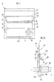
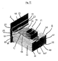
- a head plate A accomplished in proper electrically insulating plastic material is moulded together with a power cable 1, previously accomplished for its specific use.
- Said plate A substantially comprises a plane body 10 with a possible camber 11 and with a central hollow 12, said body 10 presenting two projecting longitudinal parts 13 and 14, at the two ends of which wings 13' and 14' are respectively accomplished higher with respect to plane 10.
- the cable 1 is printed together with the plate A, being covered with a printing protective covering 18 according to the prior art.
- the wings 13' and 14' and the inner side of the body 10 form openings 13A and 14A respectively, with the openings 13A and 14A having a tapering to make their closing onto the edge of a hole accomplished on sheet L of the appliance to be supplied easier, the inner sides of the openings 13A and 14A being lightly tilted.
- the plate A presents a rear shoulder 19 that is visible from the outside of the appliance and that is placed in such a way to work as a stroke end for the cover of the appliance itself, assuring consequently its steady blocking in the hole 80 of the steel sheet or casing L , in which it is housed.
- An opening 20 is accomplished in the lower part of the plate A, clearly to support the plate near the lower edge of the hole 80, which holds it and links it to the appliance.
- a shoulder 21 is made near the guide 15 to work as a stroke end during the association of a plate A with the plate C as below specified.
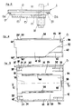
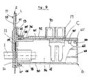
- a box structure B made of proper insulating plastic material comprises a lower part 30 substantially smooth and provided with head grooves 31 and bottom grooves 32.
- Said structure B presents then an opposing upper part 33 with a wide axial opening 34 and a further head opening 35, said box B having identical head grooves 31 and bottom grooves 32.
- Ribs 40 stiffen the sides 41 and 42 connected to the bottom 37 by means of the above mentioned lowered part 38 and the upper opening 39.
- the space of the upper part 33 between the two couples of lateral grooves 31 determines the presence of the hook-up ends 33' endowed with respective grips 33".
- the lateral sides 41 and 42 present a proper head projection 41' and 42' working as distance piece during the assembling the grounding plate as below described.
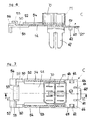
- the same central body 51 presents an end provided with a central swell 55 and two lateral protrusions 56 and 57 with stiffening ribs 58, said protrusions 56 and 57 being separated by openings 59, while a hook-up 60 with grip 60' is accomplished with a proper lowered part 51'at the opposed end, laterally to the connector block M and preferentially limited by openings 61.
- a couple of lateral brackets 62 accomplished lower with respect to the plane 51' and with the cooperation of two protrusions 63-64 and 65-66 of the plane 51' allows the housing and the retention of the connecting wires among the different components of the filter or other device to be linked to the connector M.
- Said connector M is provided with necessary electrical contacts 70 made integral with the plane 51 by over moulded or anyway fixing it to the body C, being shaped in such a way and provided with respective hook-ups to be wired with the different parts and to the grounding of the device, according to a known technique, whose constructive details are not considered necessary in this description and which are likewise variable and can be adapted to meet different needs.
- the plate C is provided with a couple of lowered planes 50 placed near the respective ends 56 and 57 and working as a shoulder and a consolidating element for the connection of the guides 36 of the box B in the grooves 54 of the slides 52 and 53.
- a hole 80 is accomplished in a proper position on the steel sheet L or casing of the appliance to be electrically supplied and presents four side widenings 80', said hole 80 and said widenings 80' being dimensioned in such a way to allow the translation of the couple of reliefs 13 and 14, besides the wings 13' and 14' placed on the plate C, the vertical distance between said openings 80' being identical to the distance between the two couples of wings 13' and 14', while the height of the hole 80 must be bigger than the outer distance of the wings 13 and 14 to allow the dropping of said wings13 and 14 until the throat 20 of the plate A leans on the bottom of the hole 80, when the wings 13' and 14' themselves disappear from the holes 80'
- the contacts 70 of the connector M are linked to the plane 51 of the supporting plate C by over moulded or anyway by applying it on the plate C itself, according one of the known techniques.
- a plate 83 is provided on the head of the plate C to allow the ground connection housed in an opening 12 and projecting from the box B thanks to the opening formed by its distance pieces 41' - 42', in order to be directly linked to the steel sheet L, by means, for example, of screws to be fixed into the holes 82.
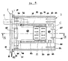
- the worker brings the plate C near the plate A in order to connect the different wires of the over moulded cable 1 to the different connections of the electrical elements 70 of the connector block M, after having applied the supporting coil 67 and after having linked its winding wires to the other wire elements housed and blocked in the lower side of the plane 51 of the plate C.
- the plate C itself is head driven along the opening 12 so that its guide 55 slides along the outer surface of the guide 15 of plate A, till its side 56 meets the shoulder 21 of plate A, which avoids its prosecution and assures its coaxiality.
- Box B and the cover or plate C are so designed that, together with the clamping of grip 60' that links box B and cover C, grips 30" and 33" snap-shut into the openings of the cross guides 15 and 16 of plate A to link box B and the closing plate A itself.
- the invention achieves also its main purpose, i.e. avoiding both the blockage of the line cable with cable clamps or any other mechanical system and the disadvantages linked to the use of insulating resins for the over mouldeding of the cable 1 onto plate A.
- the sloping of the inner sides of the wings 13' and 14' assures a progressive closing of the steel sheet L or casing into the grooves 13A - 14A, so as to guarantee a steady and immovable fitting of said group A-B-C into the seat 80 that contains and supports it, creating a reliable and safe support for connector M integrated with the RFI filter, without using any cable clamps or other mechanical fixing systems to block the power cable and without using insulating resins that make the different parts of the device not recyclable and replaceable, in accordance to the purposes of this invention.
- vent holes 31 and 32 accomplished on the lower part 30 and on the upper part 33 of box B assure the cooling of eventual coils or other overheating elements, still without resorting to any insulating resins.
- Fig. 12 to 15 represent the constructive particulars of a first constructive variation of the invention, in particular of the plate C' that supports the connector M, for an electrical connection solution of anti-disturbing for appliances that, even though reductive and less effective than the one till now described, assures however sufficient solidity and a sure minor obstacle, beyond a reduced cost.
- connector M is linked to the wall 51' of the plate that comprises analogous parts 55' and 57'-56' in order to slip itself into guides 15 and 16 of the head plate A, without being associated to some box structure element B that can be dispensed with, in order to reduce blocks of the connection.
- This invention can foresee also the partial or total replacement of the hooking elements, i.e. the hook-up 60' and 30"-33" with other movable connecting mechanical systems, or it is possible to prepare the cable 1 to be printed on any point of plate A.
Landscapes
- Details Of Connecting Devices For Male And Female Coupling (AREA)
- Insertion, Bundling And Securing Of Wires For Electric Apparatuses (AREA)
- Shielding Devices Or Components To Electric Or Magnetic Fields (AREA)
Applications Claiming Priority (3)
| Application Number | Priority Date | Filing Date | Title |
|---|---|---|---|
| ITBL20020008 | 2002-04-15 | ||
| ITBL20020008 ITBL20020008A1 (it) | 2002-04-15 | 2002-04-15 | Cavo di alimentazione e filtro incorporati, particolarmente per apparecchi elettrodomestici |
| PCT/EP2003/003854 WO2003088424A1 (en) | 2002-04-15 | 2003-04-14 | Incorporated power line cable and filter, particularly for appliances |
Publications (2)
| Publication Number | Publication Date |
|---|---|
| EP1495515A1 EP1495515A1 (en) | 2005-01-12 |
| EP1495515B1 true EP1495515B1 (en) | 2013-01-09 |
Family
ID=29227552
Family Applications (1)
| Application Number | Title | Priority Date | Filing Date |
|---|---|---|---|
| EP03727303A Expired - Lifetime EP1495515B1 (en) | 2002-04-15 | 2003-04-14 | Incorporated power line cable and filter, particularly for appliances |
Country Status (6)
| Country | Link |
|---|---|
| EP (1) | EP1495515B1 (it) |
| CN (1) | CN100377445C (it) |
| ES (1) | ES2398452T3 (it) |
| IT (1) | ITBL20020008A1 (it) |
| RU (1) | RU2293454C2 (it) |
| WO (1) | WO2003088424A1 (it) |
Families Citing this family (3)
| Publication number | Priority date | Publication date | Assignee | Title |
|---|---|---|---|---|
| ITVI20080063A1 (it) * | 2008-03-12 | 2009-09-13 | Sumoto Srl | Struttura di connettore di alimentazione. |
| ITTV20090035A1 (it) * | 2009-03-09 | 2010-09-10 | Procond Elettronica S R L | Dispositivo integrato multifunzione, particolarmente per apparecchiature elettriche. |
| EP3911132B1 (en) | 2020-05-12 | 2024-07-03 | AT & S Austria Technologie & Systemtechnik Aktiengesellschaft | Component carrier with a solid body protecting a component carrier hole from foreign material ingression |
Family Cites Families (4)
| Publication number | Priority date | Publication date | Assignee | Title |
|---|---|---|---|---|
| RU2034418C1 (ru) * | 1992-04-28 | 1995-04-30 | Бабинер Борис Менделеевич | Приборная секция |
| US5614696A (en) * | 1994-06-23 | 1997-03-25 | Structural Instrumentation, Inc. | Environmentally sealed connector for use with a load cell block |
| IT1285072B1 (it) * | 1996-04-30 | 1998-06-03 | Gibi Elettro Srl | Gruppo morsetteria-filtro integrato, in particolare per elettrodomestici. |
| US5947752A (en) * | 1998-06-09 | 1999-09-07 | Gorden Su | Video data transmission connector and transmission cable mounting arrangement |
-
2002
- 2002-04-15 IT ITBL20020008 patent/ITBL20020008A1/it unknown
-
2003
- 2003-04-14 WO PCT/EP2003/003854 patent/WO2003088424A1/en not_active Ceased
- 2003-04-14 ES ES03727303T patent/ES2398452T3/es not_active Expired - Lifetime
- 2003-04-14 RU RU2004133336/09A patent/RU2293454C2/ru active
- 2003-04-14 EP EP03727303A patent/EP1495515B1/en not_active Expired - Lifetime
- 2003-04-14 CN CNB038083841A patent/CN100377445C/zh not_active Expired - Fee Related
Also Published As
| Publication number | Publication date |
|---|---|
| RU2004133336A (ru) | 2005-05-10 |
| RU2293454C2 (ru) | 2007-02-10 |
| EP1495515A1 (en) | 2005-01-12 |
| ES2398452T8 (es) | 2013-04-08 |
| WO2003088424A1 (en) | 2003-10-23 |
| ITBL20020008A1 (it) | 2003-10-15 |
| ES2398452T3 (es) | 2013-03-19 |
| CN100377445C (zh) | 2008-03-26 |
| CN1647324A (zh) | 2005-07-27 |
Similar Documents
| Publication | Publication Date | Title |
|---|---|---|
| US7351116B2 (en) | Connecting element | |
| JP5305207B2 (ja) | 接続アダプタと接続端子及び接続アダプタとこれに対する接続素子とから成るセット | |
| TWI530027B (zh) | Slide connector | |
| KR20050082584A (ko) | 차량용 정션박스 및 그 조립방법 | |
| EP2553775B1 (en) | Fitting confirmation construction for connectors | |
| CN100382665C (zh) | 带有电气化装置的框架 | |
| EP1495515A1 (en) | Incorporated power line cable and filter, particularly for appliances | |
| KR101167575B1 (ko) | 기능성 활선 교체 모듈 | |
| MX2008003851A (es) | Conector electrico con palanca con cubierta protectora. | |
| CN106304738B (zh) | 理线总成 | |
| EP3376608B1 (en) | Connector assembly and method for assembling this connector assembly | |
| KR20090022961A (ko) | 커넥터하우징 | |
| KR100419728B1 (ko) | 전기장치의 커넥터 | |
| CN219695230U (zh) | 电流传感器 | |
| KR101348191B1 (ko) | 체결확인 가능한 커넥터 | |
| CN112285401A (zh) | 一种电能计量装置 | |
| JP4089947B2 (ja) | 電線接続機構を備える電気機器の取付構造 | |
| JP6457993B2 (ja) | 給電装置 | |
| KR101801706B1 (ko) | 커넥터 어셈블리 | |
| CN205049777U (zh) | 一种适配器卡条安装装置 | |
| CN216216267U (zh) | 一种电机三相引出线端子接线结构 | |
| CN218351868U (zh) | 一种欧规插座 | |
| EP2141777A1 (en) | Seat connection system | |
| CN205900982U (zh) | 一种防电磁干扰保护的液体加热器具 | |
| CN110994292A (zh) | 一种电子产品快充接口连接线束 |
Legal Events
| Date | Code | Title | Description |
|---|---|---|---|
| PUAI | Public reference made under article 153(3) epc to a published international application that has entered the european phase |
Free format text: ORIGINAL CODE: 0009012 |
|
| 17P | Request for examination filed |
Effective date: 20041013 |
|
| AK | Designated contracting states |
Kind code of ref document: A1 Designated state(s): AT BE BG CH CY CZ DE DK EE ES FI FR GB GR HU IE IT LI LU MC NL PT RO SE SI SK TR |
|
| 17Q | First examination report despatched |
Effective date: 20101220 |
|
| RAP1 | Party data changed (applicant data changed or rights of an application transferred) |
Owner name: D.E.M. S.P.A. |
|
| REG | Reference to a national code |
Ref country code: DE Ref legal event code: R079 Ref document number: 60343069 Country of ref document: DE Free format text: PREVIOUS MAIN CLASS: H01R0013660000 Ipc: H01R0013740000 |
|
| RIC1 | Information provided on ipc code assigned before grant |
Ipc: H01R 13/719 20110101ALI20120530BHEP Ipc: H01R 13/74 20060101AFI20120530BHEP |
|
| GRAP | Despatch of communication of intention to grant a patent |
Free format text: ORIGINAL CODE: EPIDOSNIGR1 |
|
| GRAS | Grant fee paid |
Free format text: ORIGINAL CODE: EPIDOSNIGR3 |
|
| GRAA | (expected) grant |
Free format text: ORIGINAL CODE: 0009210 |
|
| AK | Designated contracting states |
Kind code of ref document: B1 Designated state(s): DE ES FR GB IT TR |
|
| REG | Reference to a national code |
Ref country code: GB Ref legal event code: FG4D |
|
| REG | Reference to a national code |
Ref country code: DE Ref legal event code: R096 Ref document number: 60343069 Country of ref document: DE Effective date: 20130307 |
|
| REG | Reference to a national code |
Ref country code: ES Ref legal event code: FG2A Ref document number: 2398452 Country of ref document: ES Kind code of ref document: T3 Effective date: 20130319 |
|
| PLBE | No opposition filed within time limit |
Free format text: ORIGINAL CODE: 0009261 |
|
| STAA | Information on the status of an ep patent application or granted ep patent |
Free format text: STATUS: NO OPPOSITION FILED WITHIN TIME LIMIT |
|
| 26N | No opposition filed |
Effective date: 20131010 |
|
| REG | Reference to a national code |
Ref country code: DE Ref legal event code: R097 Ref document number: 60343069 Country of ref document: DE Effective date: 20131010 |
|
| REG | Reference to a national code |
Ref country code: FR Ref legal event code: PLFP Year of fee payment: 14 |
|
| REG | Reference to a national code |
Ref country code: FR Ref legal event code: PLFP Year of fee payment: 15 |
|
| REG | Reference to a national code |
Ref country code: FR Ref legal event code: PLFP Year of fee payment: 16 |
|
| PGFP | Annual fee paid to national office [announced via postgrant information from national office to epo] |
Ref country code: IT Payment date: 20210428 Year of fee payment: 19 Ref country code: FR Payment date: 20210423 Year of fee payment: 19 Ref country code: DE Payment date: 20210420 Year of fee payment: 19 |
|
| PGFP | Annual fee paid to national office [announced via postgrant information from national office to epo] |
Ref country code: GB Payment date: 20210421 Year of fee payment: 19 Ref country code: ES Payment date: 20210621 Year of fee payment: 19 Ref country code: TR Payment date: 20210409 Year of fee payment: 19 |
|
| REG | Reference to a national code |
Ref country code: DE Ref legal event code: R119 Ref document number: 60343069 Country of ref document: DE |
|
| GBPC | Gb: european patent ceased through non-payment of renewal fee |
Effective date: 20220414 |
|
| PG25 | Lapsed in a contracting state [announced via postgrant information from national office to epo] |
Ref country code: GB Free format text: LAPSE BECAUSE OF NON-PAYMENT OF DUE FEES Effective date: 20220414 Ref country code: FR Free format text: LAPSE BECAUSE OF NON-PAYMENT OF DUE FEES Effective date: 20220430 Ref country code: DE Free format text: LAPSE BECAUSE OF NON-PAYMENT OF DUE FEES Effective date: 20221103 |
|
| REG | Reference to a national code |
Ref country code: ES Ref legal event code: FD2A Effective date: 20230529 |
|
| PG25 | Lapsed in a contracting state [announced via postgrant information from national office to epo] |
Ref country code: IT Free format text: LAPSE BECAUSE OF NON-PAYMENT OF DUE FEES Effective date: 20220414 |
|
| PG25 | Lapsed in a contracting state [announced via postgrant information from national office to epo] |
Ref country code: ES Free format text: LAPSE BECAUSE OF NON-PAYMENT OF DUE FEES Effective date: 20220415 |
|
| PG25 | Lapsed in a contracting state [announced via postgrant information from national office to epo] |
Ref country code: TR Free format text: LAPSE BECAUSE OF NON-PAYMENT OF DUE FEES Effective date: 20220414 |