EP1495668A2 - Dispositif séparateur à écoulement axial - Google Patents
Dispositif séparateur à écoulement axial Download PDFInfo
- Publication number
- EP1495668A2 EP1495668A2 EP04103154A EP04103154A EP1495668A2 EP 1495668 A2 EP1495668 A2 EP 1495668A2 EP 04103154 A EP04103154 A EP 04103154A EP 04103154 A EP04103154 A EP 04103154A EP 1495668 A2 EP1495668 A2 EP 1495668A2
- Authority
- EP
- European Patent Office
- Prior art keywords
- rotor
- section
- axial
- separating device
- housing
- Prior art date
- Legal status (The legal status is an assumption and is not a legal conclusion. Google has not performed a legal analysis and makes no representation as to the accuracy of the status listed.)
- Granted
Links
- 238000011144 upstream manufacturing Methods 0.000 claims description 2
- 235000013339 cereals Nutrition 0.000 abstract description 16
- 238000000926 separation method Methods 0.000 description 10
- 230000007704 transition Effects 0.000 description 9
- 239000010908 plant waste Substances 0.000 description 7
- 239000010902 straw Substances 0.000 description 7
- 238000003306 harvesting Methods 0.000 description 3
- 239000000463 material Substances 0.000 description 3
- 238000000034 method Methods 0.000 description 3
- 238000002360 preparation method Methods 0.000 description 3
- 230000008569 process Effects 0.000 description 3
- 241001124569 Lycaenidae Species 0.000 description 2
- 239000003795 chemical substances by application Substances 0.000 description 2
- 238000004140 cleaning Methods 0.000 description 2
- 230000007423 decrease Effects 0.000 description 2
- 238000004519 manufacturing process Methods 0.000 description 2
- 230000002093 peripheral effect Effects 0.000 description 2
- 229910000831 Steel Inorganic materials 0.000 description 1
- 230000009471 action Effects 0.000 description 1
- 230000006978 adaptation Effects 0.000 description 1
- 230000008901 benefit Effects 0.000 description 1
- 230000005540 biological transmission Effects 0.000 description 1
- 238000002485 combustion reaction Methods 0.000 description 1
- 238000010276 construction Methods 0.000 description 1
- 238000005520 cutting process Methods 0.000 description 1
- 230000008021 deposition Effects 0.000 description 1
- 230000001627 detrimental effect Effects 0.000 description 1
- 238000009826 distribution Methods 0.000 description 1
- 230000000694 effects Effects 0.000 description 1
- 239000008187 granular material Substances 0.000 description 1
- 230000005484 gravity Effects 0.000 description 1
- 230000003116 impacting effect Effects 0.000 description 1
- 230000009467 reduction Effects 0.000 description 1
- 238000012216 screening Methods 0.000 description 1
- 239000007921 spray Substances 0.000 description 1
- 239000010959 steel Substances 0.000 description 1
Images



Classifications
-
- A—HUMAN NECESSITIES
- A01—AGRICULTURE; FORESTRY; ANIMAL HUSBANDRY; HUNTING; TRAPPING; FISHING
- A01F—PROCESSING OF HARVESTED PRODUCE; HAY OR STRAW PRESSES; DEVICES FOR STORING AGRICULTURAL OR HORTICULTURAL PRODUCE
- A01F7/00—Threshing apparatus
- A01F7/02—Threshing apparatus with rotating tools
- A01F7/06—Threshing apparatus with rotating tools with axles in line with the feeding direction ; Axial threshing machines
Definitions
- the invention relates to an axial separator with a Housing and a rotatably mounted therein rotor, each at least one separating section and a discharge section have, wherein the rotor is a circular cylindrical body comprises, in the separating section with good engagement elements and in the Ejection section is provided with discharge conveyor elements.
- EP 0 244 862 A describes For example, a combine harvester, where one in the tangential flow working threshing cylinder two in the axial flow process acting separating rotors are arranged downstream.
- the separation rotors are arranged within a housing, the underside of which with separating baskets is provided. At the eccentric to the rotor arranged The upper side of the housing is fitted with helical skids.
- Of the Rotor consists of axially oriented, good engagement elements carrying longitudinal struts together. At the back of the rotor are located in the ejection area elongated, axial oriented, paddle-like discharge conveyor elements.
- EP 0 522 267 A becomes a combine with the same general configuration described, however, the rotors are made of a cylindrical Body with rigidly attached elements of good action and in the Ejection area arranged paddle-shaped discharge conveyor elements built up.
- WO 01/37639 A shows a combine harvester with a single one Axialdresch- and separating device.
- the rotor also points a cylindrical body with rigidly applied elements of good engagement and paddle-shaped discharge conveyor elements in Ejection area.
- the rotor is in a housing with to it arranged concentric top.
- the EP 1 236 391 A shows a combine harvester, which also with equipped with a single Axialdresch- and separating device is.
- the rotor is made up of a cylindrical body and attached to it have good engagement elements together. Of the Diameter of the body widens in the transition area stepped between the threshing and separating sections.
- the Housing of the rotor expands in the axial direction frustoconical.
- a similar combine harvester is disclosed in US 5,688 170 A shown. There is the top of the case, however composed of cylindrical sections.
- the diameter of the circular cylindrical Body of the rotor between the separation and ejection section to grow. Due to the enlarged diameter of the Body of the rotor results in the same speed a larger one Peripheral speed on the surface of the rotor and thus an improved ejection behavior of the threshed Crop residues.
- the circulation (that is the amount continuous with the rotor encircling crop residues) of material in the Ejection section becomes strong due to the centrifugal forces acting reduced.
- the large diameter decreases at the end the rotor losses due to spray grains, as in axial Direction along the surface of the rotor towards the Ejection area to be moved grains on the radially extending transition region between separation and Bounce ejection section and reflected forward. There they can get through the baskets in the cleaning and do not get lost.
- the increase in the outer diameter of the body can be stepped or continuously.
- a relatively steep step has the Advantage that it deflected impacting grains forward become.
- the upper part of the housing of the rotor preferably defines at least in the ejection area and in the end area of the separating section a housing axis which is eccentric to the axis of rotation of the rotor is arranged.
- the housing axis is in particular above the Rotary axis arranged.
- the discharge conveyor elements are preferably paddle-shaped and extend in the axial direction of the rotor. Their number is basically arbitrary, however, has the use of four distributed around the circumference of the rotor discharge conveyor proven.
- the rotor as a welded construction, d. H. the discharge section with an enlarged diameter of the To weld separation section of the rotor.
- the discharge section With an enlarged diameter of the To weld separation section of the rotor.
- the discharge section With an enlarged diameter of the To weld separation section of the rotor.
- the discharge section With an enlarged diameter of the To weld separation section of the rotor.
- the discharge section with an enlarged diameter of the To weld separation section of the rotor.
- the discharge section With an enlarged diameter of the To weld separation section of the rotor.
- the discharge section With an enlarged diameter of the To weld separation section of the rotor.
- the discharge section With an enlarged diameter of the To weld separation section of the rotor.
- the discharge section With an enlarged diameter of the To weld separation section of the rotor.
- the discharge section With an enlarged diameter of the To weld separation section of the rotor.
- the body of the rotor with a in itself
- the ring reflects along the axis of the Rotor's moving grains and prevents in this way the Dribbling losses. He is preferably near the Ejection area of the rotor attached, since there the Dribbelumblee can be combated particularly effectively.
- the radially outer dimensions of the ring according to preferably those of the rotor elements of good contact, while the inner ones correspond to that of the body.
- the length of the ring in Axial direction of the rotor is limited, it affects the Good promotion and the separation behavior is not detrimental, In particular, when the top of the housing in his Neighborhood is arranged eccentrically to the rotor and thus a sufficient space for the crop is ready, on the ring to move past in the direction of flow.
- the Axialtrenn wrench invention can also be a Dreschabites have.
- FIG. 1 shows a self-propelled combine harvester 10 with a Support frame 12, which is supported by wheels 14 on the ground and is moved away from them.
- the wheels 14 are not by means shown drive means rotated to the combine harvester 10 z. B. to move over a field to be harvested.
- a crop gathering device 16 connected to harvest crops from the field and it up and behind by an inclined conveyor 18 threshing and To supply release agents.
- the threshing and separating agents comprise a transverse threshing drum 20 and one of these associated concave 21, which the harvested good first is supplied.
- the threshing drum 20th to omit and to use an Axialtrenn adopted, the a threshing section and a separating section. It can a single axial separator or two (or more) juxtaposed Axialtrenn adopteden use Find.
- a stripper roller 23 and a beater 22 lead together with a feed housing the threshed crop of the threshing cylinder 20 and the concave 21 of the Axialtrenn issued 24 too.
- Direction information such as front, back, above and below on the Forward direction V of the combine 10.
- Cereals and chaff which are deposited during the threshing process fall on at least one screw conveyor 30, the both feed to a preparation tray 33.
- Grain and chaff escape from the axial separation device 24 fall on a shaking tray 32, which is for passing on the Preparation floor 33 leads.
- the preparation floor 33 gives that Cereal and the chaff a screen box 34 on which a fan 36 is assigned to the deposition of the chaff from the To support grain.
- Purified grain is removed by means of a Granule 38 fed to an elevator, not shown, the it transported into a grain tank 40.
- a reverse auger 42 gives ungagged ear parts by another, not shown Elevator back into the threshing process.
- the chaff can be at the Rear of the screening device by a rotating chaff spreader be ejected.
- the purified grain from the Grain tank 40 can by a discharge system with transverse screws 44 and unloading a discharge conveyor 46.
- the systems mentioned are by means of an internal combustion engine 48 powered by an operator from a driver's cab 50 is controlled out.
- the different devices for threshing, conveying, cleaning and separating are located within the support frame 12.
- a Straw chopper 70 arranged around a horizontal, transverse to Direction of travel axis (in the figure counterclockwise) is rotationally driven. It includes a cylindrical Rotary body with pendulum pendulum knives suspended from it, the arranged in the housing 72 stationary counter knives cooperate to chop the crop residues and by means of a straw distributor plate equipped with straw guide plates 82 74 about the cutting width of the combine 10 in the field to distribute.
- a straw distributor plate equipped with straw guide plates 82 74 about the cutting width of the combine 10 in the field to distribute.
- the chute 66 could be a separate Conveyor drum for conveying the crop residues into the straw chopper 70 are inserted.
- an adjustable Straw baffle be present, which is a switching between the Chopper operation and a swath-deposit operation allowed.
- FIG. 2 shows the axial separating device 24 in more detail.
- she is composed of a housing 84 and disposed therein Rotor 86 together.
- the rotor 86 is rotatable in the housing 84 stored and is at its rear by a gear 80 in Rotation offset.
- the Axialtrenn beautiful can be in a Inlet transition section 90, a separation section 92 and a Divide ejection section 94.
- the housing 84 includes over the length of the Separation section 92 and the ejection section 94 extending lid-like upper part 88, on the inside helical Guide rails 96 are attached.
- the housing 84 in the Separation section 92 on its underside separating baskets 98 on. in the Inlet transition section 90 is the housing 84 with helical guide rails 100 equipped.
- To form the Outlet 64 is the housing 84 at its bottom in Ejection section 94 cut out and thus open at the bottom.
- the rotor 86 comprises a hollow, circular cylindrical body 102, which extends over the entire length of the rotor 86. At his lying in the direction of travel V front are on the body 102 plate-shaped Guteingriffs institute 104 attached, the Feed the crop aggressively into the inlet transition section 90. In the axial direction, smaller tine-shaped close Good engagement elements 106, over the length of the Inlet transition portion 90 are distributed. In the separating section 92 is the body 102 with also prong-shaped good engagement elements 108 provided slightly larger than the good engagement elements 106 in the inlet transition region 90 and in larger Are spaced apart from each other.
- the body 102 In the ejection section 94 is the body 102 with concentric bowl-shaped elements 110 provided that its outer diameter there to form a Enlarge level 109.
- the elements 110 Around the elements 110 are four paddle-shaped Austrag makeieri 112 distributed, extending in the axial direction of the rotor 84.
- the discharge conveyor elements 112 are on beveled at its front and rear ends.
- the Discharge Conveyors 112 are Made of Rigid Material (Steel) produced. But it could also be flexible material, such as rubber, be used.
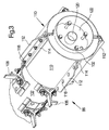
- the ejection section 94 of the rotor 86 is shown in FIG reproduced enlarged perspective view.
- the two Elements 110 each extend around half the circumference of the body 102.
- the discharge conveyor elements 112 are each through Pairs welded onto the elements 110, more rectangular Consoles 114 and through the consoles 114 and holes in the Austrag lake instituten 112 extending screws 116 and nuts 118 connected to the elements 110.
- the nuts and bolts 118 of the top and bottom shown in Figure 4 consoles 114th also fix the elements 110 to each other and thus to the body 102.
- the elements 110 could also be welded to the body 102 become.
- At the rear end of the body 102 is an end wall 122 with a centrally disposed socket 120 for Receiving a shaft (not shown) provided, which covers the body 102 connects to the transmission 80.
- FIG. 4 shows a section through the ejection region 94 of FIG Axial separator 24.
- the top 88 of the housing 84th defines a circular segment having a radius 124 whose Center 126 is above the axis of the rotor 86.
- With the Reference numeral 128 is one shown in Figs Disc marked.
- the outer diameter increases the body 102 of the rotor 86 in the ejection section 94 in stages at. Because of the eccentric arrangement of the upper part 88 has the Crop has sufficient space to follow this step can.
- the peripheral speed of the Rotor 86 relative to the separating portion 92 increased, resulting in larger centrifugal forces and thus to a better ejection behavior the crop residue leads. Besides, they will Dribbelumblee mentioned decreases because in the axial direction of the Rotor 86 backward moving grains at the stage 109 again be reflected forward and not lost.
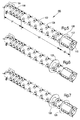
- FIG. 5 shows another embodiment of a rotor 86 shown.
- the outer diameter of the ring 128 corresponds approximately to the outer circle diameter of the Good engagement elements 108 is described while its inner diameter the outer diameter of the body 102 corresponds.
- the Ring 128 may be composed of two sub-elements, the placed on the body 102 and welded thereto. Alternatively, the ring 128 is self-contained and is in front of the Attachment of the elements 110 and / or the holders for the Good engagement elements 104, 106, 108 on the body 102nd deferred and fixed.
- the ring 128 is in last quarter of the separating section 92.
- two rings 128 are provided, the are each arranged at the points which in the figure 5 and 6 are shown.
Landscapes
- Life Sciences & Earth Sciences (AREA)
- Environmental Sciences (AREA)
- Threshing Machine Elements (AREA)
- Filling Or Emptying Of Bunkers, Hoppers, And Tanks (AREA)
Priority Applications (1)
| Application Number | Priority Date | Filing Date | Title |
|---|---|---|---|
| EP06100210A EP1647178B1 (fr) | 2003-07-05 | 2004-07-02 | Dispositif séparateur à écoulement axial |
Applications Claiming Priority (2)
| Application Number | Priority Date | Filing Date | Title |
|---|---|---|---|
| DE2003130465 DE10330465A1 (de) | 2003-07-05 | 2003-07-05 | Axialtrenneinrichtung |
| DE10330465 | 2003-07-05 |
Related Child Applications (1)
| Application Number | Title | Priority Date | Filing Date |
|---|---|---|---|
| EP06100210A Division EP1647178B1 (fr) | 2003-07-05 | 2004-07-02 | Dispositif séparateur à écoulement axial |
Publications (3)
| Publication Number | Publication Date |
|---|---|
| EP1495668A2 true EP1495668A2 (fr) | 2005-01-12 |
| EP1495668A3 EP1495668A3 (fr) | 2005-04-20 |
| EP1495668B1 EP1495668B1 (fr) | 2007-01-24 |
Family
ID=33441627
Family Applications (2)
| Application Number | Title | Priority Date | Filing Date |
|---|---|---|---|
| EP20040103154 Expired - Lifetime EP1495668B1 (fr) | 2003-07-05 | 2004-07-02 | Dispositif séparateur à écoulement axial |
| EP06100210A Expired - Lifetime EP1647178B1 (fr) | 2003-07-05 | 2004-07-02 | Dispositif séparateur à écoulement axial |
Family Applications After (1)
| Application Number | Title | Priority Date | Filing Date |
|---|---|---|---|
| EP06100210A Expired - Lifetime EP1647178B1 (fr) | 2003-07-05 | 2004-07-02 | Dispositif séparateur à écoulement axial |
Country Status (3)
| Country | Link |
|---|---|
| EP (2) | EP1495668B1 (fr) |
| DE (3) | DE10330465A1 (fr) |
| DK (1) | DK1495668T3 (fr) |
Cited By (3)
| Publication number | Priority date | Publication date | Assignee | Title |
|---|---|---|---|---|
| CN100399874C (zh) * | 2006-03-17 | 2008-07-09 | 钱志义 | 可调式轴流滚筒脱粒装置 |
| EP3473079A1 (fr) * | 2017-09-27 | 2019-04-24 | CLAAS Selbstfahrende Erntemaschinen GmbH | Rotor de séparation pour moissoneuse batteuse |
| CN113068518A (zh) * | 2021-04-29 | 2021-07-06 | 河南科技大学 | 一种油牡丹籽脱粒、干燥和脱壳工艺及自动化生产线 |
Citations (6)
| Publication number | Priority date | Publication date | Assignee | Title |
|---|---|---|---|---|
| US4274426A (en) | 1980-03-31 | 1981-06-23 | Williams Dennis W | Threshing apparatus |
| EP0244862A1 (fr) | 1986-05-09 | 1987-11-11 | Deere & Company | Moissonneuses-batteuses |
| EP0522267A2 (fr) | 1991-05-10 | 1993-01-13 | Deere & Company | Séparateur axial |
| WO2001037639A1 (fr) | 1999-11-26 | 2001-05-31 | New Holland Belgium Nv | Moyen de dechargement pour unite de battage et de separation de moissonneuse-batteuse |
| EP1236391A1 (fr) | 2001-03-02 | 2002-09-04 | Deere & Company | Unité de traitement de récolte pour moissonneuse-batteuse |
| DE10217466A1 (de) | 2002-04-19 | 2003-12-24 | Deere & Co | Axialabscheider mit Leitschiene |
Family Cites Families (5)
| Publication number | Priority date | Publication date | Assignee | Title |
|---|---|---|---|---|
| BE788802A (nl) * | 1971-07-06 | 1973-01-02 | Clayson Nv | Verbeteringen aan maaidorsers. |
| US4198802A (en) * | 1977-08-18 | 1980-04-22 | Deere & Company | Axial flow rotary separator for a combine |
| DE2830103C2 (de) * | 1978-07-08 | 1982-09-23 | Deere & Co., Moline, Ill., US, Niederlassung Deere & Co. European Office, 6800 Mannheim | Reinigungsvorrichtung für Mähdrescher |
| US5356338A (en) | 1993-04-26 | 1994-10-18 | Deere & Company | Axial rotor having an independently driven threshing section and separating section |
| DE19640047A1 (de) * | 1996-09-30 | 1998-04-02 | Claas Ohg | Mähdrescher |
-
2003
- 2003-07-05 DE DE2003130465 patent/DE10330465A1/de not_active Withdrawn
-
2004
- 2004-07-02 DE DE200450004967 patent/DE502004004967D1/de not_active Expired - Lifetime
- 2004-07-02 EP EP20040103154 patent/EP1495668B1/fr not_active Expired - Lifetime
- 2004-07-02 DK DK04103154T patent/DK1495668T3/da active
- 2004-07-02 EP EP06100210A patent/EP1647178B1/fr not_active Expired - Lifetime
- 2004-07-02 DE DE200450002738 patent/DE502004002738D1/de not_active Expired - Lifetime
Patent Citations (6)
| Publication number | Priority date | Publication date | Assignee | Title |
|---|---|---|---|---|
| US4274426A (en) | 1980-03-31 | 1981-06-23 | Williams Dennis W | Threshing apparatus |
| EP0244862A1 (fr) | 1986-05-09 | 1987-11-11 | Deere & Company | Moissonneuses-batteuses |
| EP0522267A2 (fr) | 1991-05-10 | 1993-01-13 | Deere & Company | Séparateur axial |
| WO2001037639A1 (fr) | 1999-11-26 | 2001-05-31 | New Holland Belgium Nv | Moyen de dechargement pour unite de battage et de separation de moissonneuse-batteuse |
| EP1236391A1 (fr) | 2001-03-02 | 2002-09-04 | Deere & Company | Unité de traitement de récolte pour moissonneuse-batteuse |
| DE10217466A1 (de) | 2002-04-19 | 2003-12-24 | Deere & Co | Axialabscheider mit Leitschiene |
Cited By (3)
| Publication number | Priority date | Publication date | Assignee | Title |
|---|---|---|---|---|
| CN100399874C (zh) * | 2006-03-17 | 2008-07-09 | 钱志义 | 可调式轴流滚筒脱粒装置 |
| EP3473079A1 (fr) * | 2017-09-27 | 2019-04-24 | CLAAS Selbstfahrende Erntemaschinen GmbH | Rotor de séparation pour moissoneuse batteuse |
| CN113068518A (zh) * | 2021-04-29 | 2021-07-06 | 河南科技大学 | 一种油牡丹籽脱粒、干燥和脱壳工艺及自动化生产线 |
Also Published As
| Publication number | Publication date |
|---|---|
| DK1495668T3 (da) | 2007-05-07 |
| DE502004004967D1 (de) | 2007-10-25 |
| EP1647178A1 (fr) | 2006-04-19 |
| DE502004002738D1 (de) | 2007-03-15 |
| DE10330465A1 (de) | 2005-02-24 |
| EP1495668B1 (fr) | 2007-01-24 |
| EP1495668A3 (fr) | 2005-04-20 |
| EP1647178B1 (fr) | 2007-09-12 |
Similar Documents
| Publication | Publication Date | Title |
|---|---|---|
| EP1358789B1 (fr) | Moissonneuse-batteuse avec hache-paille | |
| DE2000553C3 (fr) | ||
| EP2250870B1 (fr) | Agencement de hachage et de répartition de résidus de produits de récolte pour une moissonneuse-batteuse | |
| DE2729033C2 (fr) | ||
| DE2635266C3 (de) | Axialdreschmaschine eines Mähdreschers | |
| EP2250868B1 (fr) | Agencement de hachage et de distribution de résidus de produits de récolte pour une moissonneuse-batteuse | |
| EP1421843B1 (fr) | Moissonneuse-batteuse avec hache-paille | |
| EP2286655B1 (fr) | Agencement de hachage et de répartition de résidus de produits de récolte pour une moissonneuse-batteuse | |
| EP0522267B1 (fr) | Séparateur axial | |
| DE2462568A1 (de) | Dreschmaschine, insbesondere maehdrescher | |
| EP2286654B1 (fr) | Agencement de hachage et de répartition de résidus de produits de récolte pour une moissonneuse-batteuse | |
| EP0521280B1 (fr) | Séparateur axial | |
| DE2233018A1 (de) | Maehdrescher der axialflussbauart | |
| DE2729012A1 (de) | Maehdrescher | |
| EP2250869B1 (fr) | Agencement de hachage et de répartition de résidus de produits de récolte pour une moissonneuse-batteuse | |
| EP2384610B1 (fr) | Agencement de hachage et de répartition de résidus de produits de récolte pour une moissonneuse-batteuse | |
| EP0162431A1 (fr) | Machine de récolte | |
| DE102016217609B4 (de) | Mähdrescher mit Strohrutsche und Strohförderer | |
| DE10314081B4 (de) | Austrageinrichtung zum Austragen von Erntegut aus einer Erntemaschine | |
| EP3369301B1 (fr) | Moissonneuse | |
| EP1354508B1 (fr) | Separateur axial avec rail de guidage | |
| EP1495668B1 (fr) | Dispositif séparateur à écoulement axial | |
| EP1842415B1 (fr) | Déflecteur pour un dispositif de répartition d'un système à hacher la paille | |
| BE1021334B1 (de) | Mähdrescher mit einer zwischen der drescheinrichtung und der reinigung angeordneten nachdrescheinrichtung | |
| EP1864566B1 (fr) | Moissonneuse-batteuse dotée d'un transporteur séparateur de grains entre le dispositif de nettoyage et le distributeur de vannure |
Legal Events
| Date | Code | Title | Description |
|---|---|---|---|
| PUAI | Public reference made under article 153(3) epc to a published international application that has entered the european phase |
Free format text: ORIGINAL CODE: 0009012 |
|
| AK | Designated contracting states |
Kind code of ref document: A2 Designated state(s): AT BE BG CH CY CZ DE DK EE ES FI FR GB GR HU IE IT LI LU MC NL PL PT RO SE SI SK TR |
|
| AX | Request for extension of the european patent |
Extension state: AL HR LT LV MK |
|
| PUAL | Search report despatched |
Free format text: ORIGINAL CODE: 0009013 |
|
| AK | Designated contracting states |
Kind code of ref document: A3 Designated state(s): AT BE BG CH CY CZ DE DK EE ES FI FR GB GR HU IE IT LI LU MC NL PL PT RO SE SI SK TR |
|
| AX | Request for extension of the european patent |
Extension state: AL HR LT LV MK |
|
| 17P | Request for examination filed |
Effective date: 20051020 |
|
| AKX | Designation fees paid |
Designated state(s): BE DE DK FR GB IT |
|
| GRAP | Despatch of communication of intention to grant a patent |
Free format text: ORIGINAL CODE: EPIDOSNIGR1 |
|
| RIN1 | Information on inventor provided before grant (corrected) |
Inventor name: LAUER, FRITZ Inventor name: WEICHHOLDT, DIRK Inventor name: PREECE, DAVID |
|
| GRAS | Grant fee paid |
Free format text: ORIGINAL CODE: EPIDOSNIGR3 |
|
| GRAA | (expected) grant |
Free format text: ORIGINAL CODE: 0009210 |
|
| AK | Designated contracting states |
Kind code of ref document: B1 Designated state(s): BE DE DK FR GB IT |
|
| REG | Reference to a national code |
Ref country code: GB Ref legal event code: FG4D Free format text: NOT ENGLISH |
|
| REF | Corresponds to: |
Ref document number: 502004002738 Country of ref document: DE Date of ref document: 20070315 Kind code of ref document: P |
|
| GBT | Gb: translation of ep patent filed (gb section 77(6)(a)/1977) |
Effective date: 20070228 |
|
| REG | Reference to a national code |
Ref country code: DK Ref legal event code: T3 |
|
| ET | Fr: translation filed | ||
| PLBE | No opposition filed within time limit |
Free format text: ORIGINAL CODE: 0009261 |
|
| STAA | Information on the status of an ep patent application or granted ep patent |
Free format text: STATUS: NO OPPOSITION FILED WITHIN TIME LIMIT |
|
| 26N | No opposition filed |
Effective date: 20071025 |
|
| PGFP | Annual fee paid to national office [announced via postgrant information from national office to epo] |
Ref country code: FR Payment date: 20080729 Year of fee payment: 5 Ref country code: IT Payment date: 20080724 Year of fee payment: 5 |
|
| PGFP | Annual fee paid to national office [announced via postgrant information from national office to epo] |
Ref country code: GB Payment date: 20080729 Year of fee payment: 5 |
|
| GBPC | Gb: european patent ceased through non-payment of renewal fee |
Effective date: 20090702 |
|
| REG | Reference to a national code |
Ref country code: FR Ref legal event code: ST Effective date: 20100331 |
|
| PG25 | Lapsed in a contracting state [announced via postgrant information from national office to epo] |
Ref country code: FR Free format text: LAPSE BECAUSE OF NON-PAYMENT OF DUE FEES Effective date: 20090731 |
|
| PG25 | Lapsed in a contracting state [announced via postgrant information from national office to epo] |
Ref country code: GB Free format text: LAPSE BECAUSE OF NON-PAYMENT OF DUE FEES Effective date: 20090702 |
|
| PG25 | Lapsed in a contracting state [announced via postgrant information from national office to epo] |
Ref country code: IT Free format text: LAPSE BECAUSE OF NON-PAYMENT OF DUE FEES Effective date: 20090702 |
|
| PGFP | Annual fee paid to national office [announced via postgrant information from national office to epo] |
Ref country code: DE Payment date: 20140619 Year of fee payment: 11 Ref country code: DK Payment date: 20140725 Year of fee payment: 11 |
|
| PGFP | Annual fee paid to national office [announced via postgrant information from national office to epo] |
Ref country code: BE Payment date: 20140730 Year of fee payment: 11 |
|
| REG | Reference to a national code |
Ref country code: DE Ref legal event code: R119 Ref document number: 502004002738 Country of ref document: DE |
|
| REG | Reference to a national code |
Ref country code: DK Ref legal event code: EBP Effective date: 20150731 |
|
| PG25 | Lapsed in a contracting state [announced via postgrant information from national office to epo] |
Ref country code: DE Free format text: LAPSE BECAUSE OF NON-PAYMENT OF DUE FEES Effective date: 20160202 |
|
| PG25 | Lapsed in a contracting state [announced via postgrant information from national office to epo] |
Ref country code: DK Free format text: LAPSE BECAUSE OF NON-PAYMENT OF DUE FEES Effective date: 20150731 |
|
| PG25 | Lapsed in a contracting state [announced via postgrant information from national office to epo] |
Ref country code: BE Free format text: LAPSE BECAUSE OF NON-PAYMENT OF DUE FEES Effective date: 20150731 |