EP1495825A2 - Procédé de brasage - Google Patents
Procédé de brasage Download PDFInfo
- Publication number
- EP1495825A2 EP1495825A2 EP04015875A EP04015875A EP1495825A2 EP 1495825 A2 EP1495825 A2 EP 1495825A2 EP 04015875 A EP04015875 A EP 04015875A EP 04015875 A EP04015875 A EP 04015875A EP 1495825 A2 EP1495825 A2 EP 1495825A2
- Authority
- EP
- European Patent Office
- Prior art keywords
- brazing
- components
- radiator
- brazing material
- furnace
- Prior art date
- Legal status (The legal status is an assumption and is not a legal conclusion. Google has not performed a legal analysis and makes no representation as to the accuracy of the status listed.)
- Withdrawn
Links
Images

Classifications
-
- B—PERFORMING OPERATIONS; TRANSPORTING
- B23—MACHINE TOOLS; METAL-WORKING NOT OTHERWISE PROVIDED FOR
- B23K—SOLDERING OR UNSOLDERING; WELDING; CLADDING OR PLATING BY SOLDERING OR WELDING; CUTTING BY APPLYING HEAT LOCALLY, e.g. FLAME CUTTING; WORKING BY LASER BEAM
- B23K1/00—Soldering, e.g. brazing, or unsoldering
- B23K1/0008—Soldering, e.g. brazing, or unsoldering specially adapted for particular articles or work
- B23K1/0012—Brazing of heat exchangers
-
- B—PERFORMING OPERATIONS; TRANSPORTING
- B23—MACHINE TOOLS; METAL-WORKING NOT OTHERWISE PROVIDED FOR
- B23K—SOLDERING OR UNSOLDERING; WELDING; CLADDING OR PLATING BY SOLDERING OR WELDING; CUTTING BY APPLYING HEAT LOCALLY, e.g. FLAME CUTTING; WORKING BY LASER BEAM
- B23K1/00—Soldering, e.g. brazing, or unsoldering
- B23K1/008—Soldering within a furnace
-
- F—MECHANICAL ENGINEERING; LIGHTING; HEATING; WEAPONS; BLASTING
- F28—HEAT EXCHANGE IN GENERAL
- F28F—DETAILS OF HEAT-EXCHANGE AND HEAT-TRANSFER APPARATUS, OF GENERAL APPLICATION
- F28F9/00—Casings; Header boxes; Auxiliary supports for elements; Auxiliary members within casings
- F28F9/02—Header boxes; End plates
- F28F9/04—Arrangements for sealing elements into header boxes or end plates
- F28F9/16—Arrangements for sealing elements into header boxes or end plates by permanent joints, e.g. by rolling
- F28F9/18—Arrangements for sealing elements into header boxes or end plates by permanent joints, e.g. by rolling by welding
Definitions
- the present invention relates to a brazing method for providing excellent bonding condition.
- a conventional brazing method for a heat exchanger is disclosed in Japanese Patent Application Publication No. H10-286666.
- a surface of a fin, a tube or a plate is clad (i. e. , coated) with a brazing material, and then, both of them are assembled. After that, a heat treatment is performed so that they are brazed.
- the brazing material is composed of Cu, 6 to 15wt.% of Sn, 5 to 7 wt.% of Ni, and 5 to 8 wt.% of P so that the melting point of the brazing material is lowered.
- the heat treatment is performed in inert gas atmosphere such as nitrogen gas or argon gas at a temperature between 680°C and 700°C during three minutes.
- the brazing material steadily penetrates between components so that the components are steadily bonded.
- a portion e.g., a bonding portion between a tube and a tank
- the oxide film is not removed by a reducing function of phosphorous in the brazing material.
- the penetration (i.e., fluidity) of the brazing material is deteriorated by the oxide film. Therefore, to improve the penetration (i.e., fluidity) of the brazing material, a flux is necessitated.
- a cost of the flux is added. Further, additional processes for applying the flux and for removing the flux after brazing are necessitated so that a manufacturing cost is increased.
- a brazing method for providing excellent bonding state Specifically, in the method, a brazing material of Cu-Sn-Ni-P alloy is used without any flux.
- a brazing method for brazing components includes the steps of: coating a bonding portion between the components with a brazing material made of Cu-Sn-Ni-P alloy; introducing reducing gas into a brazing furnace; mounting the components in the brazing furnace; and increasing temperature in the brazing furnace so that the components are brazed.
- the reducing gas can remove an oxide film disposed on the surfaces of the components without using a flux.
- the brazing material steadily penetrates into the bonding portion between the components so that the components are brazed steadily.
- the components are a part of a heat exchanger, in which inner fluid flows.
- the brazing method is suitably used for the heat exchanger, which necessitates water-tightness or air-tightness by the brazing method.
- the brazing material is made of Cu, 6 to 15wt.% of Sn, 5 to 7 wt.% of Ni, and 5 to 8 wt.% of P.
- the temperature in the brazing furnace after the step of increasing the temperature is in a range between 600°C and 800°C.
- a brazing method according to a preferred embodiment is provided.
- the method is suitably used for a heat exchanger made of copper or copper alloy.
- the brazing method is applied to a radiator 100 for cooling an engine (not shown) of a construction machine, as shown in Figs. 1A to 2B.
- a fin 111 is made of copper based material, and other components are made of brass based material.
- the fin 111 and other components are bonded together by the brazing method with a copper based brazing material (described in detail later).
- the radiator 100 is composed of a core 110, an upper tank 120, and a lower tank 130.
- the core 110 is a heat exchanger for cooling coolant water (i.e., the inner fluid flowing through the radiator 100) discharged from the engine.
- the core 110 is composed of a fin 111, a tube 112, a side plate 113 and a core plate 114.
- the fin 111 is a heat radiator for radiating heat of the coolant water to a cooling wind side effectively.
- the fin 111 is formed from a thin band plate into a corrugated plate.
- the tube 112 is a member for passing the coolant water inside thereof.
- the tube 112 is formed such that the thin band plate is folded to be a flat oval in a cross section thereof, and then, both edges of the thin band plate are welded.
- the fin 111 and the tube 112 are alternately laminated so that they are aligned in a left-right direction in Fig. 1A.
- a side plate 113 as a reinforcing member is disposed outside of the outermost laminated fin 111 in the laminated fins 111, which is disposed outermost in the laminated direction.
- multiple allays e.g., three allays
- the core plate 114 is a shallow box shaped component having a standing periphery for engaging with the opening of each of the upper and lower tanks 120, 130.
- the core plate 114 is formed from a flat plate by a folding method or a drawing method.
- Multiple burring holes 114a are formed in a part of the core plate 114, which corresponds to an edge of the tube 112 (i.e., a tube edge 112a) in a longitudinal direction.
- the burring hole 114a has a flange protruding to the inside of the tank.
- the tube edge 112a is inserted into the burring hole 114a.
- the fin 111, the tube 112, the side plate 113 and the core plate 114 are brazed at each connecting portion.
- the upper and lower tanks 120, 130 are box shaped vessels having the opening disposed on a core plate 114 side.
- the opening of the tank 120, 130 is brazed with the core plate 114 so that they are brazed.
- An inlet pipe 121 and an outlet pipe 131 are brazed on each surface of the tanks 120, 130 disposed on an opposite tube side (i.e., a top or bottom surface of the tank 120, 130), respectively.
- the inlet pipe 121 and the outlet pipe 131 connect to the inside of the tanks 120, 130, respectively.
- the radiator 100 is completed.
- the coolant water discharged from the engine is introduced into the radiator through the inlet pipe 121, and then, the coolant water flows through the upper tank 120, the core 110 (i. e. , the tube 112), and the lower tank 130. Then, the coolant water flows out of the radiator 100 through the outlet pipe 131. The coolant water is cooled while flowing through the radiator 100.
- the brazing method of the radiator 100 according to the preferred embodiment is described as follows.
- the brazing material is made of alloy composing copper (i.e., Cu), tin (i.e., Sn), nickel (i.e., Ni), and phosphorous (i.e., P). Each weight percentage is, for example, 75% of copper, 15% of tin, 5% of nickel and 5% of phosphorous, respectively.
- the melting point of the brazing material is about 600°C.
- the brazing material is preliminarily applied on each surface of the components (112-114, 120, 121, 130, 131) except for the fin 111. Then, the components (111-114, 120, 121, 130, 131) are engaged together and they are fixed by a jig so that the radiator 100 is temporarily assembled.
- the temporary assembly of the radiator 100 is disposed in a brazing furnace so that the components (111-114, 120, 121, 130, 131) are integrally brazed.
- hydrogen gas i.e., H 2
- Brazing temperature condition is in a range between 600°C and 800°C.
- the brazing method is suitably used for the radiator (i.e. , the heat exchanger) 100, which necessitates the water-tightness or air-tightness between the tube 112 and the core plate 114 by the brazing method.
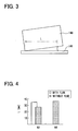
- Figs. 3 and 4 explain a testing method for confirming the effect of the brazing method and a test result.
- Fig. 3 explains the testing method for confirming the effect.
- a clearance having a predetermined slant angle is provided between an upper test piece 140 and a lower test piece 141. Then, the brazing material 1 is sandwiched by the upper and lower test pieces 140, 141.
- a fillet length L of the brazing material 1, which is formed in the clearance, is measured. The fillet length L is defined as shown in Fig. 3.
- Fig. 4 shows the result of the test.
- the fillet length L is obtained to be the same length as the conventional method with using the nitrogen furnace and with using flux.
- the actual brazing condition (i.e., the fixation) between the tube 112 and the core plate 114 is such that, in the conventional method, defective penetration of the brazing material is occurred in about one-third of the total number of joint of tube 112 and core plate 114.
- the defect is mainly occurred at a rounding portion (i.e., R portion) of the tube 112.
- all fixations provide excellent penetration of the brazing material.
- the brazing material is made of the Cu-Sn-Ni-P alloy, the melting point is lowered in the brazing process so that the reduction of strength of the components is prevented.
- the reducing gas in the brazing process is the hydrogen gas
- the reducing gas can be a carbon monoxide gas (CO) or the like.
- the brazing method is used for the radiator 100 of the construction machine, the method can be used for another radiator of another four-wheel vehicle. Furthermore, the method can be used for another heat exchanger instead of the radiator 100, for example, an intercooler, a condenser, a heater core, an evaporator or the like.
Landscapes
- Engineering & Computer Science (AREA)
- Mechanical Engineering (AREA)
- Physics & Mathematics (AREA)
- Thermal Sciences (AREA)
- General Engineering & Computer Science (AREA)
- Details Of Heat-Exchange And Heat-Transfer (AREA)
- Heat-Exchange Devices With Radiators And Conduit Assemblies (AREA)
- Die Bonding (AREA)
Applications Claiming Priority (2)
| Application Number | Priority Date | Filing Date | Title |
|---|---|---|---|
| JP2003271462 | 2003-07-07 | ||
| JP2003271462A JP2005028412A (ja) | 2003-07-07 | 2003-07-07 | ろう付け方法 |
Publications (2)
| Publication Number | Publication Date |
|---|---|
| EP1495825A2 true EP1495825A2 (fr) | 2005-01-12 |
| EP1495825A3 EP1495825A3 (fr) | 2006-05-10 |
Family
ID=33448040
Family Applications (1)
| Application Number | Title | Priority Date | Filing Date |
|---|---|---|---|
| EP04015875A Withdrawn EP1495825A3 (fr) | 2003-07-07 | 2004-07-06 | Procédé de brasage |
Country Status (3)
| Country | Link |
|---|---|
| US (1) | US20050006443A1 (fr) |
| EP (1) | EP1495825A3 (fr) |
| JP (1) | JP2005028412A (fr) |
Families Citing this family (7)
| Publication number | Priority date | Publication date | Assignee | Title |
|---|---|---|---|---|
| US20110297359A1 (en) * | 2010-06-04 | 2011-12-08 | Jack Chisenhall | System and method for attaching stainless steel side plates to the copper/brass tubes of a heat exchanger core |
| MX363089B (es) * | 2010-10-25 | 2019-03-08 | Mitsubishi Shindo Kk | Aleacion de cobre resistente a la presion y resistente a la corrosion de una estructura cobresoldada, y metodo para producir una estructura cobresoldada. |
| US9224517B2 (en) * | 2011-04-07 | 2015-12-29 | Hitachi Chemical Company, Ltd. | Paste composition for electrode and photovoltaic cell |
| US20120260982A1 (en) * | 2011-04-14 | 2012-10-18 | Hitachi Chemical Company, Ltd. | Paste composition for electrode, photovoltaic cell element, and photovoltaic cell |
| US20120260981A1 (en) * | 2011-04-14 | 2012-10-18 | Hitachi Chemical Company, Ltd. | Paste composition for electrode, photovoltaic cell element, and photovoltaic cell |
| US20130118573A1 (en) * | 2011-11-14 | 2013-05-16 | Hitachi Chemical Company, Ltd. | Paste composition for electrode, photovoltaic cell element, and photovoltaic cell |
| CN111761156A (zh) * | 2020-07-22 | 2020-10-13 | 厦门福鑫特工贸有限公司 | 大型计算机散热器的钎焊方法 |
Family Cites Families (9)
| Publication number | Priority date | Publication date | Assignee | Title |
|---|---|---|---|---|
| US2093814A (en) * | 1934-09-29 | 1937-09-21 | Gen Motors Corp | Method and apparatus for brazing |
| US2140531A (en) * | 1937-11-26 | 1938-12-20 | Richard R Kennedy | Cadmium alloy solders |
| US3666520A (en) * | 1969-09-10 | 1972-05-30 | Sumitomo Light Metal Ind | Process of forming a metallic copper layer on the surface of workpiece of aluminum or aluminum base alloy |
| DE3216934C1 (de) * | 1982-05-06 | 1983-08-25 | Daimler-Benz Ag, 7000 Stuttgart | Verfahren zum wasserstoff-undurchlaessigen Hartverloeten austenitischer Stahlbauteile |
| US4538757A (en) * | 1983-08-01 | 1985-09-03 | Motorola, Inc. | Wave soldering in a reducing atmosphere |
| JPS6149771A (ja) * | 1984-08-15 | 1986-03-11 | Nippon Radiator Co Ltd | 熱交換器 |
| US5378294A (en) * | 1989-11-17 | 1995-01-03 | Outokumpu Oy | Copper alloys to be used as brazing filler metals |
| FI87470C (fi) * | 1989-11-17 | 1993-01-11 | Outokumpu Oy | Som slaglod anvaendbara kopparlegeringar |
| US5249733A (en) * | 1992-07-16 | 1993-10-05 | At&T Bell Laboratories | Solder self-alignment methods |
-
2003
- 2003-07-07 JP JP2003271462A patent/JP2005028412A/ja active Pending
-
2004
- 2004-07-06 EP EP04015875A patent/EP1495825A3/fr not_active Withdrawn
- 2004-07-06 US US10/885,554 patent/US20050006443A1/en not_active Abandoned
Also Published As
| Publication number | Publication date |
|---|---|
| EP1495825A3 (fr) | 2006-05-10 |
| US20050006443A1 (en) | 2005-01-13 |
| JP2005028412A (ja) | 2005-02-03 |
Similar Documents
| Publication | Publication Date | Title |
|---|---|---|
| US20060086491A1 (en) | Heat exchanger and method of manufacturing the same | |
| US6000461A (en) | Method and apparatus for controlled atmosphere brazing of folded tubes | |
| US20080237312A1 (en) | Brazing method | |
| US8800642B2 (en) | Heat exchanger with side plate having a through hole | |
| KR102267269B1 (ko) | 플럭스-프리 cab 브레이징용 알루미늄 재료 | |
| US7401726B2 (en) | Brazing method | |
| KR20010024615A (ko) | 열교환기 | |
| US6371201B1 (en) | Heat exchanger and method of assembly for automotive vehicles | |
| JP6642659B2 (ja) | 熱交換器 | |
| CA2542746C (fr) | Echangeur thermique a plaques | |
| US20010054496A1 (en) | Heat exchanger having plural tubes connected to header tanks by brazing | |
| EP1495825A2 (fr) | Procédé de brasage | |
| JP5633205B2 (ja) | アルミニウム管と銅管の接合方法および接合構造ならびにこの接合構造を有する熱交換器 | |
| WO2017018438A1 (fr) | Échangeur de chaleur et son procédé de fabrication | |
| JP4328445B2 (ja) | 積層型熱交換器 | |
| US20070160868A1 (en) | Brazing method and brazed structure | |
| JP2000158070A (ja) | 熱交換器用チューブ | |
| JP5515877B2 (ja) | 熱交換器 | |
| US20110284198A1 (en) | Method for joining components made of a high-strength aluminum material and heat exchanger assembled according to the method | |
| JP4626472B2 (ja) | 熱交換器および熱交換器の製造方法 | |
| JP2005331176A (ja) | 熱交換器 | |
| JP2005030755A (ja) | 熱交換器の製造方法および熱交換器 | |
| JP4866571B2 (ja) | 熱交換器 | |
| JP2007144496A (ja) | 接合構造体及びその製造方法 | |
| JP4682765B2 (ja) | 熱交換器および熱交換器の製造方法 |
Legal Events
| Date | Code | Title | Description |
|---|---|---|---|
| PUAI | Public reference made under article 153(3) epc to a published international application that has entered the european phase |
Free format text: ORIGINAL CODE: 0009012 |
|
| AK | Designated contracting states |
Kind code of ref document: A2 Designated state(s): AT BE BG CH CY CZ DE DK EE ES FI FR GB GR HU IE IT LI LU MC NL PL PT RO SE SI SK TR |
|
| AX | Request for extension of the european patent |
Extension state: AL HR LT LV MK |
|
| PUAL | Search report despatched |
Free format text: ORIGINAL CODE: 0009013 |
|
| AK | Designated contracting states |
Kind code of ref document: A3 Designated state(s): AT BE BG CH CY CZ DE DK EE ES FI FR GB GR HU IE IT LI LU MC NL PL PT RO SE SI SK TR |
|
| AX | Request for extension of the european patent |
Extension state: AL HR LT LV MK |
|
| AKX | Designation fees paid | ||
| STAA | Information on the status of an ep patent application or granted ep patent |
Free format text: STATUS: THE APPLICATION IS DEEMED TO BE WITHDRAWN |
|
| 18D | Application deemed to be withdrawn |
Effective date: 20061111 |
|
| REG | Reference to a national code |
Ref country code: DE Ref legal event code: 8566 |