EP1495843A1 - Pistolet électrique à clouer - Google Patents
Pistolet électrique à clouer Download PDFInfo
- Publication number
- EP1495843A1 EP1495843A1 EP04015490A EP04015490A EP1495843A1 EP 1495843 A1 EP1495843 A1 EP 1495843A1 EP 04015490 A EP04015490 A EP 04015490A EP 04015490 A EP04015490 A EP 04015490A EP 1495843 A1 EP1495843 A1 EP 1495843A1
- Authority
- EP
- European Patent Office
- Prior art keywords
- cylinder
- plunger
- coil
- receiving chamber
- nailing
- Prior art date
- Legal status (The legal status is an assumption and is not a legal conclusion. Google has not performed a legal analysis and makes no representation as to the accuracy of the status listed.)
- Withdrawn
Links
- 239000000872 buffer Substances 0.000 claims abstract description 6
- 230000001360 synchronised effect Effects 0.000 claims description 2
- 230000002093 peripheral effect Effects 0.000 description 6
- 230000005611 electricity Effects 0.000 description 5
- 230000035939 shock Effects 0.000 description 5
- 230000000694 effects Effects 0.000 description 3
- XEEYBQQBJWHFJM-UHFFFAOYSA-N Iron Chemical group [Fe] XEEYBQQBJWHFJM-UHFFFAOYSA-N 0.000 description 2
- 230000003139 buffering effect Effects 0.000 description 2
- 239000000463 material Substances 0.000 description 2
- 239000004809 Teflon Substances 0.000 description 1
- 229920006362 Teflon® Polymers 0.000 description 1
- 238000006073 displacement reaction Methods 0.000 description 1
- -1 for example Substances 0.000 description 1
- 230000017525 heat dissipation Effects 0.000 description 1
- 230000001105 regulatory effect Effects 0.000 description 1
Images


Classifications
-
- B—PERFORMING OPERATIONS; TRANSPORTING
- B25—HAND TOOLS; PORTABLE POWER-DRIVEN TOOLS; MANIPULATORS
- B25C—HAND-HELD NAILING OR STAPLING TOOLS; MANUALLY OPERATED PORTABLE STAPLING TOOLS
- B25C1/00—Hand-held nailing tools; Nail feeding devices
- B25C1/06—Hand-held nailing tools; Nail feeding devices operated by electric power
Definitions
- the present invention relates generally to an electric nailing gun and, more particularly to such an electric nailing gun, which provides good plunger buffering and heat dissipation effects.
- a plunger In a conventional electric nailing gun, electricity is connected to a coil to produce a magnetic field, causing a plunger to move rapidly to the barrel and to achieve a nailing action.
- electricity disconnected from the coil the plunger is pushed back to its former standby position by a spring.
- the rapid return stroke of the plunger after each nailing action upon disconnection of electricity from the coil causes the plunger to strike the housing of the electric nailing gun directly, thereby causing damage to the housing or displacement of the plunger.
- Shock absorbing blocks may be mounted inside the housing of the electric nailing gun to absorb shocks upon each return stroke of the plunger.
- the shock absorbing blocks wear quickly with use, and may fall out of place upon striking of the plunger. When a shock absorbing block fell out of place, the fallen shock absorbing block may interfere with the action of the plunger.
- the present invention has been accomplished under the circumstances in view. It is the main object of the present invention to provide an electric nailing gun, which buffers the return stroke of the plunger by means of regulating the flow of air.
- the electric nailing gun comprises a housing having a receiving chamber; a barrel located on a front side of the housing; a nail magazine connected between the barrel and the housing; a nail driving mechanism mounted inside the housing and having a fixed coil holder provided with an axially extended center through hole, a plunger slidably mounted in the axially extended center through hole of the coil holder and movable between a standby position and a nailing position, spring means supporting the plunger in the standby position, and a coil wound round the coil holder and adapted to cause the plunger to move from the standby position to the nailing position when electrically connected; and a piston head located on a top side of the plunger for synchronous motion.
- the piston head has an outer diameter smaller than a diameter of the receiving chamber of the housing and greater than an outer diameter of the plunger.
- the piston head is adapted to force air below toward the coil during a forward stroke of the plunger from the standby position to the nailing position, and to compress air above and to further buffer returning speed of the plunger during a return stroke of the plunger from the nailing position to the standby position.
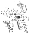
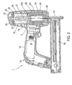
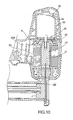
- an electric nailing gun 1 is shown comprised of a gun body, a nail driving mechanism 20 , a piston head comprised of a disk member 30 and a friction ring 40 , and a cylinder 50 .
- the aforesaid gun body is comprised of a housing 10 formed of two symmetrical half shells 11 , the housing having a head 12 , a handle 13 , and a receiving chamber 14 defined in the head 12, a barrel 15 forwardly extended from the front side of the head 12 of the housing 10, and a nail magazine 16 connected between the barrel 15 and the rear end of the handle 13 .
- the nail driving mechanism 20 is mounted in the receiving chamber 14 inside the housing 10 , comprised of a plunger 21 , a driving tip 22 , a coil holder 23 , a coil 24 , spring means, for example, a conical spring 25 , and a cushion 26 .
- the plunger 21 is a cylindrical iron core having a top screw hole 211 in the top end.
- the driving tip 22 is fixedly fastened to the bottom end of the plunger 21 .
- the coil holder 23 has an axially extended center through hole 231 , which receives the plunger 21 .
- the coil 24 is mounted on the periphery of the coil holder 23 .
- the coil 24 When electricity connected to the coil 24 , the coil 24 is energized, and therefore the iron core, namely, the plunger 21 is forced to move axially along the center through hole 231 of the coil holder 23 .
- the coil holder 23 has a plurality of raised female retaining portions 233 and outwardly downwardly sloping guide faces 234 alternatively arranged in the top wall 232 around the center through hole 231 .
- the conical spring 25 is sleeved onto the plunger 21 and supported on the top wall 232 of the coil holder 23 .
- the cushion 26 is located on the bottom side of the coil holder 23 around the center through hole 231 .
- the piston head is comprised of the disk member 30 and the friction ring 40 .
- the disk member 30 has a diameter greater than the plunger 21 .
- the disk member 30 has a center through hole 33 cut through the top surface 31 and the bottom surface 32 , and a locating groove 34 extended around the periphery.
- a screw rod 35 is inserted through the center through hole 33 and threaded into the top screw hole 211 of the plunger 21 to fixedly secure the disk member 30 to the top end of the plunger 21 .
- the piston head which comprises the disk member 30 and the friction ring 40 , and the plunger 21 , which serves as a piston rod, form a piston movable in the cylinder 50 .
- the friction ring 40 is made of wear resistant material, for example, Teflon. Referring also to FIGS. 5 and 6, the friction ring 40 is a split ring having a bevel split 41 and an outer peripheral wall 42 . The friction ring 40 is fastened to the locating groove 34 of the disk member 30 .
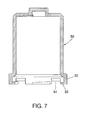
- the cylinder 50 is shaped like a cap having a top close end, a bottom open end and an inside receiving chamber.
- the cylinder 50 comprises a plurality of bottom notches 51 and bottom protruding blocks 52 equiangularly and alternatively arranged around the bottom open side, a plurality of male retaining portions 53 respectively inwardly projecting from the bottom protruding blocks 52 , a top mounting hole 51 in the top wall, a top through hole 55 through the top wall, and a deformable valve flap 56 mounted on the inside and adapted to close the through hole 55 .
- the valve flap 56 has a plug 561 disposed at one end and fastened to the mounting hole 54 such that the body of the valve flap 56 covers and closes the through hole 55 .
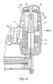
- FIG. 9 shows the status of the electric nailing gun 1 before action.
- the plunger 21 is in the standby position P1
- the conical spring 25 is fully extended and supports the disk member 30 at the top side inside the cylinder 50
- the valve flap 56 closes the through hole 55 .
- the coil 24 when electricity connected to the coil 24 , the coil 24 is energized to produce a magnetic field, thereby causing the plunger 21 to move downwards rapidly, and the driving tip 22 is moved toward the nailing position P2 .
- air outside the cylinder 50 passes downwards to move the valve flap 56 away from the through hole 55 and to enter the receiving chamber of the cylinder 50, and at the same time air inside the receiving chamber of the cylinder 50 below the disk member 30 is squeezed out of the cylinder 50 through the exhaust port A and guided outwards by the guide faces 234 toward the coil 24 to carry heat away from the coil 24 .
- the conical spring 25 pushes the plunger 21 back to the standby position P1 (see FIG. 9), thereby causing the valve flap 56 to close the through hole 55 again.
- the air inside the receiving chamber of the cylinder 50 above the disk member 30 is compressed, buffering the return speed of the plunger 21.
- the invention control air intake and exhaust volume to buffer the return stroke of the plunger 21 from the nailing position P2 to the standby position P1 without affecting the nail driving action, eliminating the drawback of the prior art design of impact between parts. Further, during air flow exchange between intake and exhaust, exhaust air carries heat away from the coil 24 , lowering the inside temperature of the housing 10 . Therefore, the invention is an innovative design having an industrial value.
- the aforesaid disk member 30 and friction ring 40 form a piston head movable in the cylinder 50.
- the piston head can be directly formed of a round block of wear resistant material peripherally disposed in slight contact with the inside wall of the cylinder 50 .
- the housing 10 can be made to provide directly a receiving chamber for the reciprocating motion of the piston to substitute for the cylinder 50 .
- FIG. 11 shows an electric nailing gun 2 according to the second preferred embodiment of the present invention.
- the electric nailing gun 2 according to this embodiment is substantially similar to the aforesaid first embodiment of the present invention with the exception of the features outlined hereinafter.
- the top end of the plunger 21 is directly fixedly mounted with a disk member 60 and a deformable circular gasket 70.
- the disk member 60 has an outer diameter not greater than the diameter of the receiving chamber of the cylinder 50 , and a plurality of peripheral notches 61 arranged around the periphery.
- the diameter of the gasket 70 is approximately equal to the disk member 60 .
- the gasket 70 is closely attached to the top side of the disk member 60 to block the periphery notches 61 .
Landscapes
- Engineering & Computer Science (AREA)
- Mechanical Engineering (AREA)
- Portable Nailing Machines And Staplers (AREA)
- Percussive Tools And Related Accessories (AREA)
- Toys (AREA)
- Telescopes (AREA)
Applications Claiming Priority (2)
| Application Number | Priority Date | Filing Date | Title |
|---|---|---|---|
| CNU032654006U CN2644112Y (zh) | 2003-07-04 | 2003-07-04 | 电动钉枪 |
| CN03265400U | 2003-07-04 |
Publications (1)
| Publication Number | Publication Date |
|---|---|
| EP1495843A1 true EP1495843A1 (fr) | 2005-01-12 |
Family
ID=29430777
Family Applications (1)
| Application Number | Title | Priority Date | Filing Date |
|---|---|---|---|
| EP04015490A Withdrawn EP1495843A1 (fr) | 2003-07-04 | 2004-07-01 | Pistolet électrique à clouer |
Country Status (5)
| Country | Link |
|---|---|
| US (1) | US20050001008A1 (fr) |
| EP (1) | EP1495843A1 (fr) |
| JP (1) | JP3099962U (fr) |
| CN (1) | CN2644112Y (fr) |
| DE (1) | DE20312381U1 (fr) |
Families Citing this family (7)
| Publication number | Priority date | Publication date | Assignee | Title |
|---|---|---|---|---|
| US8899460B2 (en) * | 2007-06-12 | 2014-12-02 | Black & Decker Inc. | Magazine assembly for nailer |
| CN101386183B (zh) * | 2007-09-13 | 2010-12-08 | 旭吉股份有限公司 | 打钉机的反作用力抵消装置 |
| CN201389838Y (zh) * | 2009-03-27 | 2010-01-27 | 张汉勤 | 射钉发射装置 |
| CN107812875B (zh) * | 2017-12-01 | 2024-02-13 | 苏州弘瀚自动化科技有限公司 | 一种拉钉机械手 |
| EP3838496A1 (fr) * | 2019-12-20 | 2021-06-23 | Hilti Aktiengesellschaft | Appareil de travail |
| US12162125B2 (en) * | 2020-10-30 | 2024-12-10 | Milwaukee Electric Tool Corporation | Powered fastener driver |
| WO2025092299A1 (fr) * | 2023-11-03 | 2025-05-08 | 南京泉峰科技有限公司 | Pistolet à clous |
Citations (4)
| Publication number | Priority date | Publication date | Assignee | Title |
|---|---|---|---|---|
| US3141171A (en) * | 1961-12-22 | 1964-07-21 | Fastener Corp | Electric power tool |
| US3172121A (en) * | 1963-04-01 | 1965-03-09 | Fastener Corp | Electrically operated fastener driving tool |
| US4293088A (en) * | 1979-10-12 | 1981-10-06 | Swingline Inc. | Electronically operated portable fastener driving tool |
| US4573624A (en) * | 1982-08-28 | 1986-03-04 | Erwin Muller Gmbh & Co. | Portable electric stapler |
Family Cites Families (11)
| Publication number | Priority date | Publication date | Assignee | Title |
|---|---|---|---|---|
| US4183453A (en) * | 1977-04-10 | 1980-01-15 | Swingline, Inc. | Electronically operated portable fastener driving tool |
| US4305541A (en) * | 1979-10-01 | 1981-12-15 | Swingline Inc. | Electronically operated portable nail gun |
| DE3232120A1 (de) * | 1982-08-28 | 1984-03-01 | Robert Bosch Gmbh, 7000 Stuttgart | Elektromagnetisch betriebenes einschlaggeraet |
| DE3236748C2 (de) * | 1982-10-05 | 1994-05-19 | Black & Decker Inc | Elektrisch angetriebener Tacker |
| DE3405906A1 (de) * | 1984-02-18 | 1985-08-22 | Robert Bosch Gmbh, 7000 Stuttgart | Eintreibgeraet fuer befestigungsmittel, insbesondere elektrotacker |
| DE3437019C2 (de) * | 1984-10-09 | 1994-01-20 | Bosch Gmbh Robert | Elektromagnetisch betriebenes Einschlaggerät mit einem Luftdämpfer |
| US4573621A (en) * | 1985-04-22 | 1986-03-04 | Black & Decker Inc. | Electro-magnetic tacker |
| GB2265106B (en) * | 1992-03-18 | 1995-07-05 | Max Co Ltd | Air-pressure-operated impulsion mechanism |
| US6796475B2 (en) * | 2000-12-22 | 2004-09-28 | Senco Products, Inc. | Speed controller for flywheel operated hand tool |
| US6364193B1 (en) * | 2001-05-29 | 2002-04-02 | Acumen Power Tools Corp. | Electric nailing tool |
| US6662990B1 (en) * | 2003-01-03 | 2003-12-16 | Modern Pioneer Ltd. | Buffer apparatus of electrical nailing gun |
-
2003
- 2003-07-04 CN CNU032654006U patent/CN2644112Y/zh not_active Expired - Fee Related
- 2003-08-08 US US10/636,605 patent/US20050001008A1/en not_active Abandoned
- 2003-08-11 DE DE20312381U patent/DE20312381U1/de not_active Expired - Lifetime
- 2003-08-20 JP JP2003270660U patent/JP3099962U/ja not_active Expired - Fee Related
-
2004
- 2004-07-01 EP EP04015490A patent/EP1495843A1/fr not_active Withdrawn
Patent Citations (4)
| Publication number | Priority date | Publication date | Assignee | Title |
|---|---|---|---|---|
| US3141171A (en) * | 1961-12-22 | 1964-07-21 | Fastener Corp | Electric power tool |
| US3172121A (en) * | 1963-04-01 | 1965-03-09 | Fastener Corp | Electrically operated fastener driving tool |
| US4293088A (en) * | 1979-10-12 | 1981-10-06 | Swingline Inc. | Electronically operated portable fastener driving tool |
| US4573624A (en) * | 1982-08-28 | 1986-03-04 | Erwin Muller Gmbh & Co. | Portable electric stapler |
Also Published As
| Publication number | Publication date |
|---|---|
| JP3099962U (ja) | 2004-04-22 |
| DE20312381U1 (de) | 2003-11-06 |
| US20050001008A1 (en) | 2005-01-06 |
| CN2644112Y (zh) | 2004-09-29 |
Similar Documents
| Publication | Publication Date | Title |
|---|---|---|
| US4776408A (en) | Pneumatic impact tool | |
| CA2200159C (fr) | Dispositif de retenue de piston pour outils cloueurs mus par gaz de combustion | |
| EP1398118B1 (fr) | Mécanisme de suspension pour un moteur de ventilateur d'un outil entraîné par gaz de combustion | |
| EP1588804B1 (fr) | Outil entraîné par gaz de combustion | |
| EP0017635B1 (fr) | Appareil pneumatique à percussion | |
| JP4690346B2 (ja) | ファスナ駆動工具用の緩衝装置 | |
| JP2552566B2 (ja) | 打撃工具 | |
| JP2012505760A (ja) | 釘打機 | |
| JPH09234677A5 (fr) | ||
| EP1495843A1 (fr) | Pistolet électrique à clouer | |
| CN108527255B (zh) | 一种打钉力可调的蚊钉枪 | |
| US3688848A (en) | Air spring bleed assembly | |
| US6059167A (en) | End base of a power stapler | |
| CN111390843A (zh) | 电动工具及其控制方法 | |
| US5029744A (en) | Mechanism for controlling the powder impact force on a projectile | |
| US5135150A (en) | Pole-type powder actuated tool | |
| US2831404A (en) | Recoil buffer for guns | |
| CN103029102A (zh) | 驱动器 | |
| US4651912A (en) | Hammer-activated fastener tool | |
| US20210146520A1 (en) | Piston | |
| US3468465A (en) | Power actuated tool | |
| CN115648128A (zh) | 送钉装置以及电动卷钉枪 | |
| US11185969B2 (en) | Pneumatic tool having movable air tube | |
| JP2018130823A (ja) | 衝撃装置、衝撃装置の打撃力調整方法、及び衝撃装置の打撃音周波数調整方法 | |
| US20240263901A1 (en) | Buffered Bolt Catch |
Legal Events
| Date | Code | Title | Description |
|---|---|---|---|
| PUAI | Public reference made under article 153(3) epc to a published international application that has entered the european phase |
Free format text: ORIGINAL CODE: 0009012 |
|
| AK | Designated contracting states |
Kind code of ref document: A1 Designated state(s): AT BE BG CH CY CZ DE DK EE ES FI FR GB GR HU IE IT LI LU MC NL PL PT RO SE SI SK TR |
|
| AX | Request for extension of the european patent |
Extension state: AL HR LT LV MK |
|
| AKX | Designation fees paid | ||
| REG | Reference to a national code |
Ref country code: DE Ref legal event code: 8566 |
|
| STAA | Information on the status of an ep patent application or granted ep patent |
Free format text: STATUS: THE APPLICATION IS DEEMED TO BE WITHDRAWN |
|
| 18D | Application deemed to be withdrawn |
Effective date: 20050713 |