EP1495899B1 - Vehicule roulant - Google Patents
Vehicule roulant Download PDFInfo
- Publication number
- EP1495899B1 EP1495899B1 EP03712826A EP03712826A EP1495899B1 EP 1495899 B1 EP1495899 B1 EP 1495899B1 EP 03712826 A EP03712826 A EP 03712826A EP 03712826 A EP03712826 A EP 03712826A EP 1495899 B1 EP1495899 B1 EP 1495899B1
- Authority
- EP
- European Patent Office
- Prior art keywords
- transmission
- turning
- straight forward
- traveling
- transmission system
- Prior art date
- Legal status (The legal status is an assumption and is not a legal conclusion. Google has not performed a legal analysis and makes no representation as to the accuracy of the status listed.)
- Expired - Lifetime
Links
Images



Classifications
-
- B—PERFORMING OPERATIONS; TRANSPORTING
- B60—VEHICLES IN GENERAL
- B60K—ARRANGEMENT OR MOUNTING OF PROPULSION UNITS OR OF TRANSMISSIONS IN VEHICLES; ARRANGEMENT OR MOUNTING OF PLURAL DIVERSE PRIME-MOVERS IN VEHICLES; AUXILIARY DRIVES FOR VEHICLES; INSTRUMENTATION OR DASHBOARDS FOR VEHICLES; ARRANGEMENTS IN CONNECTION WITH COOLING, AIR INTAKE, GAS EXHAUST OR FUEL SUPPLY OF PROPULSION UNITS IN VEHICLES
- B60K17/00—Arrangement or mounting of transmissions in vehicles
- B60K17/28—Arrangement or mounting of transmissions in vehicles characterised by arrangement, location, or type of power take-off
-
- B—PERFORMING OPERATIONS; TRANSPORTING
- B60—VEHICLES IN GENERAL
- B60K—ARRANGEMENT OR MOUNTING OF PROPULSION UNITS OR OF TRANSMISSIONS IN VEHICLES; ARRANGEMENT OR MOUNTING OF PLURAL DIVERSE PRIME-MOVERS IN VEHICLES; AUXILIARY DRIVES FOR VEHICLES; INSTRUMENTATION OR DASHBOARDS FOR VEHICLES; ARRANGEMENTS IN CONNECTION WITH COOLING, AIR INTAKE, GAS EXHAUST OR FUEL SUPPLY OF PROPULSION UNITS IN VEHICLES
- B60K17/00—Arrangement or mounting of transmissions in vehicles
- B60K17/04—Arrangement or mounting of transmissions in vehicles characterised by arrangement, location or kind of gearing
- B60K17/10—Arrangement or mounting of transmissions in vehicles characterised by arrangement, location or kind of gearing of fluid gearing
- B60K17/105—Units comprising at least a part of the gearing and a torque-transmitting axle, e.g. transaxles
-
- B—PERFORMING OPERATIONS; TRANSPORTING
- B62—LAND VEHICLES FOR TRAVELLING OTHERWISE THAN ON RAILS
- B62D—MOTOR VEHICLES; TRAILERS
- B62D11/00—Steering non-deflectable wheels; Steering endless tracks or the like
- B62D11/02—Steering non-deflectable wheels; Steering endless tracks or the like by differentially driving ground-engaging elements on opposite vehicle sides
- B62D11/06—Steering non-deflectable wheels; Steering endless tracks or the like by differentially driving ground-engaging elements on opposite vehicle sides by means of a single main power source
- B62D11/10—Steering non-deflectable wheels; Steering endless tracks or the like by differentially driving ground-engaging elements on opposite vehicle sides by means of a single main power source using gearings with differential power outputs on opposite sides, e.g. twin-differential or epicyclic gears
-
- B—PERFORMING OPERATIONS; TRANSPORTING
- B62—LAND VEHICLES FOR TRAVELLING OTHERWISE THAN ON RAILS
- B62D—MOTOR VEHICLES; TRAILERS
- B62D11/00—Steering non-deflectable wheels; Steering endless tracks or the like
- B62D11/02—Steering non-deflectable wheels; Steering endless tracks or the like by differentially driving ground-engaging elements on opposite vehicle sides
- B62D11/06—Steering non-deflectable wheels; Steering endless tracks or the like by differentially driving ground-engaging elements on opposite vehicle sides by means of a single main power source
- B62D11/10—Steering non-deflectable wheels; Steering endless tracks or the like by differentially driving ground-engaging elements on opposite vehicle sides by means of a single main power source using gearings with differential power outputs on opposite sides, e.g. twin-differential or epicyclic gears
- B62D11/14—Steering non-deflectable wheels; Steering endless tracks or the like by differentially driving ground-engaging elements on opposite vehicle sides by means of a single main power source using gearings with differential power outputs on opposite sides, e.g. twin-differential or epicyclic gears differential power outputs being effected by additional power supply to one side, e.g. power originating from secondary power source
- B62D11/18—Steering non-deflectable wheels; Steering endless tracks or the like by differentially driving ground-engaging elements on opposite vehicle sides by means of a single main power source using gearings with differential power outputs on opposite sides, e.g. twin-differential or epicyclic gears differential power outputs being effected by additional power supply to one side, e.g. power originating from secondary power source the additional power supply being supplied hydraulically
-
- Y—GENERAL TAGGING OF NEW TECHNOLOGICAL DEVELOPMENTS; GENERAL TAGGING OF CROSS-SECTIONAL TECHNOLOGIES SPANNING OVER SEVERAL SECTIONS OF THE IPC; TECHNICAL SUBJECTS COVERED BY FORMER USPC CROSS-REFERENCE ART COLLECTIONS [XRACs] AND DIGESTS
- Y10—TECHNICAL SUBJECTS COVERED BY FORMER USPC
- Y10T—TECHNICAL SUBJECTS COVERED BY FORMER US CLASSIFICATION
- Y10T74/00—Machine element or mechanism
- Y10T74/19—Gearing
- Y10T74/19149—Gearing with fluid drive
Definitions
- the present invention relates to a traveling vehicle.
- a traveling vehicle in which power can be transmittedfrom a continuously variable transmission device for turning which is interlockingly connected with an engine to a power transmission system for turning which is disposed in the inside of a front transmission part, while power can be transmitted from a continuously variable transmission device for traveling straight forward which is interlockingly connected with the engine to a power transmission system for traveling straight forward which is disposed in the front transmission part by way of a rear transmission part, and these powers of the power transmission system for turning and the power transmission system for traveling straight forward are combined by a planetary gear mechanism which is disposed in the front mission part, and a resultant force is transmitted to left-and-right-side drive wheels respectively.
- a PTO shaft is interlockingly connected with the rear transmission part by way of a PTO transmission part, and a power transmission system for PTO is disposed in the PTO transmission part so that the speed of the PTO shaft can be changed in plural stages due to the power transmission system for PTO.
- a parking brake is provided to the outside of the front transmission part.
- the front transmission part, the rear transmission part and the PTO transmission part are respectively formed as separate bodies and hence, it is necessary to provide transmission means such as transmission shafts for interlockingly connecting these transmission parts with each other and hence, time and efforts are necessary for an operation to interlockingly connect these transmission parts and, at the same time, it is difficult to arrange these transmission systems in a compact manner as a whole.
- the parking brake is provided outside the front transmission part, it is necessary to provide a protective cover to protect the parking brake from splashed mud, soil and the like.
- a forward/backward traveling changeover lever is interlockingly connected with the transmission device for traveling straight forward by way of an operation mechanism for traveling straight forward.
- the continuously variable transmission device for turning is operated by a steering wheel by way of an operation mechanism for turning and, at the same time, the transmission device for traveling straight forward is operated by the forward/backward traveling changeover lever by way of the operation mechanism for traveling straight forward thus enabling a given steering operation.
- JP-9-202258A teaches a traveling vehicle according to the preamble of the enclosed claim.
- a traveling vehicle has the features in accordance with the enclosed claim.
- the transmission part includes a transmission front lid portion, a transmission body portion which is integrally formed with an axle case, and a transmission intermediate portion which is provided between the transmission front lid portion and the transmission body portion.
- the power transmission system for traveling straight forward, the power transmission system for turning, a power transmission system for PTO and a power transmission system for driving a pump are integrally disposed.
- Power inputted to the traveling vehicle from the prime mover part through the transmission front lid portion is branched and transmitted into the power transmission system for traveling straight forward, the power transmission system for turning, and a power transmission system for PTO in the transmission intermediate portion and the transmission front lid portion.
- a parking brake and a PTO clutch are arranged in the above-mentioned mission intermediate portion.
- Fig. 1 is a side view of a traveling vehicle according to the present invention.
- Fig. 2 is a plan view of a transmission part of the traveling vehicle.
- Fig. 3 is a side view of the transmission part.
- Fig. 4 is a front view of the transmission part.
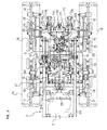
- Fig. 5 is a conceptual explanatory view of a power transmission system in the inside of the transmission part.
- Fig. 6 is a front explanatory view of the transmission part.
- Fig. 7 is a cross-sectional side view of a booster.
- Fig. 8 is a cross-sectional plan view of the booster.
- Fig. 9 is a cross-sectional back view of the booster.
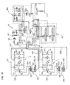
- Fig. 10 is a hydraulic circuit diagram.
- Symbol A shown in Fig. 1 to Fig. 4 indicates a traveling vehicle according to the present invention, wherein the traveling vehicle A spans a body frame 2 between a pair of left and right crawler type traveling parts 1, 1, provides a prime mover part 3 in front of the body frame 2, provides a driver part 4 at a rear portion, and provides a transmission part 5 at a position below the driver part.
- each traveling part 1 includes a traveling frame 10 which extends in the fore-and-aft direction, front and rear driven wheels 11, 12 which are respectively mounted on front and rear end portions of the traveling frame 10, a drive wheel 13 which is arranged between both front and rear driven wheels 11, 12 and at an upper position, and a crawler belt 14 which is wound around between movable wheels 11, 12, 13 and has a triangular shape as viewed from the side.
- Numeral 15 indicates a front pivot shaft for a driven wheel
- numeral 16 indicates a rear pivot shaft for a driven wheel
- numeral 17 indicates a pivot shaft for a drive wheel
- numeral 18 indicates an adjuster for advanced or retracted position of the front driven wheel
- numeral 19 indicates an equalizer
- numeral 20 indicates a crawler belt removal prevention body
- symbol ⁇ indicates an angle at which a crawler belt leaves a ground level.
- a pair of front and rear connection frames 21, 22 which extend in the left and right direction are extended in a traversing manner.
- the body frame 2 includes, as shown in Fig. 1 to Fig. 4 , a pair of left and right body frame forming members 23, 23 which extend in the fore-and-aft direction, a transmission part 5 which is extended between rear portions of the body frame forming members 23, 23, and axle case 24 which is formed such that the axle case 24 extends outwardly in the left and right direction from left-and-right side rear portions of the transmission part 5.
- an engine E is mounted between front portions of the pair of left and right body frame forming members 23, 23, a radiator 27 is arranged in front of the engine E, and these elements are covered with a bonnet 28.
- a flywheel portion 29 is interlockingly provided at a rear portion of the engine E, while the transmission part 5 is interlockingly connected the flywheel portion 29 by way of a transmission shaft 30.
- a driver part support body 31 is formed on an intermediate portion of the body frame 2
- a steering column 32 is mounted on a front portion of the driver part support body 31 in an erected manner
- a steering wheel 34 is mounted on an upper end portion of the steering column 32 by way of a wheel support shaft 33
- a driver seat 35 is arranged at a position behind the steering wheel 34.
- a fuel tank 36 is arranged at a left-side position of the driver seat 35 and a battery 37 is arranged at a right-side position of the driver seat 35.
- a floor portion 38 is formed in an extended manner.
- Left and right support frame bodies 39,39 are made to extend rearwardly and upwardly from intermediate portions at left and right sides of the floor portion 38 and a proximal end portion of a frontward/backward traveling changeover lever (transmission lever) 40 is mounted on the right support frame body 39 by way of a lever mounting body 41.
- Numeral 190 indicates a canopy.
- the transmission part 5 is, as shown in Fig. 2 and Fig. 3 , configured that a transmission front lid portion 42, a transmission body portion 43 which is integrally formed with the axle case 24, and a transmission intermediate portion 44 which is formed between the transmission front lid portion 42 and the transmission body portion 43 are replaceably connected with each other.
- a HST 6 for traveling straight forward which is a hydrostatic continuously variable transmission device as the transmission device for traveling straight forward
- a HST 7 for turning which is a hydrostatic continuously variable transmission device as the continuously variable transmission device for turning are interlocking and closely arranged with each other in a juxtaposed state on the left and right sides.
- the transmission body portion 43 and the axle case 24 are integrally formed compactly and hence, the transmission body 43 and the axle case 24 can be simply and surely mounted on the body frame 2.
- the power transmission system 45 for traveling straight forward, the power transmission system 46 for turning, the power transmission system 47 for PTO and the power transmission system 48 for driving the pump are integrally arranged.
- An input shaft 49 which is mounted in the transmission front lid portion 42 is interlockingly connected with the engine E by way of the flywheel portion 29 and the transmission shaft 30.
- the power inputted through the input shaft 49 is transmitted to the power transmission system 45 for traveling straight forward and the power transmission system 46 for turning in the inside of the transmission intermediate portion 44, while the power inputted through the input shaft 49 is transmitted to the power transmission system 47 for PTO and the power transmission system 48 for driving a pump in the inside of the transmission front lid portion 42. That is, the power inputted through the input shaft 49 is transmitted by dividing these power transmission systems 45, 46, 47, 49 in two sets.
- the power transmission system 45 for traveling straight forward is interposed between the input shaft 49 mounted in the transmission front lid portion 42 and the drive shaft 50 extended with an axis thereof directed in the left-and-right direction in the axle case 24.
- Sun gears 52, 52 of planetary gear mechanism 51, 51 which are arranged on left and right side portions in the axle case 24 are interlockingly connected with left and right end portions of the drive shaft 50.
- the input shaft 49 is extended with an axis thereof directed in the fore-and-aft direction of the vehicle body in the transmission front lid portion 42, wherein a first output gear 53 is mounted on a rear end portion of the input shaft 49 in the inside of the transmission intermediate portion 44, an input gear 55 for traveling straight forward is meshed with the first output gear 53 by way of an intermediate gear 54 for traveling straight forward in the transmission intermediate portion 44, and the input gear 55 for traveling straight forward is mounted on an input shaft 56 for traveling straight forward of the HST 6 for traveling straight forward having an axis thereof directed in the fore-and-aft direction at the right side portion of the transmission front lid portion 42.
- Numeral 57 indicates a first intermediate shaft which is extended between the transmission front lid portion 42 and the transmission intermediate portion 44 while having an axis thereof directed in the fore-and-aft direction.
- a front end portion of a first transmission shaft 59 for traveling straight forward which has an axis thereof extended in the fore-and-aft direction is interlockingly connected in the inside of the transmission body portion 43.
- a second transmission shaft 61 for traveling straight forward is interlockingly connected with the first transmission shaft 59 for traveling straight forward by way of a speed change shaft 60 for traveling straight forward.
- the drive shaft 50 is interlockingly connected with a rear end portion of the second transmission shaft 61 for traveling straight forward by way of bevel gears 62, 63.
- the speed-change shaft 60 for traveling straight forward and the second transmission shaft 61 for traveling straight forward are respectively extended in the inside of the transmission body portion 43 while having axes thereof extended in the fore-and-aft direction. Further, these shafts 60, 61 are arranged in a parallel state with the first transmission shaft 59 for traveling straight forward.
- a large-diameter gear 64 and a small-diameter gear 65 are mounted on the first transmission shaft 59 for traveling straight forward, while a small-diameter speed-change gear 66 which is meshed with the above-mentioned large-diameter gear 64, a large-diameter speed-change gear 67 which is meshed with the above-mentioned small-diameter gear 65, and a speed-change output gear 68 are mounted on the speed-change shaft 60 for traveling straight forward. Further, a second input gear 69 for traveling straight forward which is mounted on the second transmission shaft 61 for traveling straight forward is meshed with the speed-change output gear 68. Numeral 113 indicates a shifter for speed-change operation for traveling straight forward.
- a parking brake 70 is interlockingly connected, wherein the parking brake 70 is disposed in the inside of the transmission intermediate portion 44.
- the power transmission system 46 for turning is, as shown in Fig. 5 , interposed between the input shaft 4 9 mounted in the transmission front lid portion 42 and ring gears 72, 72 of the planetary gear mechanisms 51, 51 which are arranged at left and right side portions in the axle case 24.
- an input gear 74 for turning is meshed by way of an intermediate gear 73 for turning in the inside of the transmission intermediate portion 44.
- the input gear 74 for turning is mounted on an input shaft 75 for turning of the HST 7 for turning which has an axis thereof directed in the fore-and-aft direction at the left side portion of the transmission front lid portion 42.
- Numeral 76 indicates a second intermediate shaft which is extended between the transmission front lid portion 42 and the transmission intermediate portion 44 while having an axis thereof directed in the fore-and-aft direction.
- a second transmission shaft 79 which is extended in the inside of the transmission body portion 43 while having an axis thereof extended in the fore-and-aft direction is interlockingly connected by way of a first transmission shaft 78 for turning which is extended over the transmission front lid portion 42, the transmission intermediate portion 44 and the transmission body portion 43 while having an axis thereof directed in the fore-and-aft direction.
- a pair of left and right third transmission shafts 80, 80 for turning which are extended in the inside of the transmission body portion 43 while having axes thereof directed in the left and right direction are interlockingly connected.
- outer end portions of the respective third transmission shafts 80, 80 for turning are respectively interlockingly connected with the ring gears 72, 72 of the planetary gear mechanisms 51, 51.
- an output gear 81 for turning which is mounted on the output shaft 77 for turning is meshed with the large-diameter speed-change gear 82 which is rotatably mounted on the input shaft 75 for turning.
- a small-diameter speed-change gear 83 which is integrally formed with the large-diameter speed-change gear 82
- a first input gear 84 for turning which is mounted on the first transmission shaft 78 for turning is meshed.
- a first output gear 85 for turning which is mounted on the first transmission shaft 78 for turning a second input gear 86 for turning which is mounted on the second transmission shaft 79 for turning is meshed.
- third input bevel gears 88, 88 for turning which are mounted on inner end portions of the pair of left and right third transmission shafts 80, 80 for turning are meshed.
- third output gears 89, 89 for turning which are mounted on outer end portions of the respective third transmission shafts 80, 80 for turning, the ring gears 72, 72 are meshed by way of intermediate gears 90, 90.
- the planetary gear mechanism 51 is constituted such that a primary gear 91 is interposed between the above-mentioned sun gear 52 and the ring gear 72 and a drive wheel support shaft 17 is interlockingly connected with the primary gear 91 by way of a cage 92.
- the power transmission system 47 for PTO is, as shown in Fig. 5 , interposed between the input shaft 49 which is mounted in the transmission front lid portion 42 and a PTO shaft 93 which is extended with an axis thereof directed in the fore-and-aft direction in the axle case 24 and, at the same time, has a rear end portion thereof projected rearwardly from the axle case 24.
- an input gear 96 for PTO is meshed by way of an intermediate gear 95 for PTO which is mounted on the second intermediate shaft 76.
- the input gear 96 for PTO is mounted on an input shaft 97 for PTO which is extended in the inside of the transmission front lid portion 42 with an axis thereof directed in the fore-and-aft direction.
- a first transmission shaft 99 for PTO which is extended in the inside of the transmission body portion 43 while having an axis thereof directed in the fore-and-aft direction is interlockingly connected by way of a PTO clutch 98 which is arranged in the inside of the transmission intermediate portion 44.
- the above-mentioned PTO shaft 93 is interlockingly connected by way of a speed-change shaft 100 which is extended in the inside of the transmission intermediate portion 44 while having an axis thereof extended in the fore-and-aft direction.
- first to fourth output gears 101, 102, 103, 104 are mounted on the first transmission shaft 99 for PTO
- first to third speed-change gears 105, 106, 107 which are respectively meshed with the first to third output gears 101, 102, 103 are mounted on the PTO speed-change shaft 100.
- a reverse rotation gear 108 is meshed with the fourth output gear 104 by way of a counter gear 109 and the counter gear 109 is mounted on the counter shaft 110 which is extended in the inside of the transmission body portion 43 while having an axis thereof directed in the fore-and-aft direction.
- Numerals 111, 112 indicate first and second speed-change operation shifter for PTO.
- the power transmission system 48 for driving the pump is, as shown in Fig. 5 , interposed between the input shaft 49 which is mounted in the transmission front lid portion 42 and a pump drive shaft 114 which is extended over the transmission front lid portion 42 and the transmission intermediate portion 44 while having an axis thereof directed in the fore-and-aft direction.
- a tandem type charge pump P is interlockingly connected with the pump drive shaft 114 so as to drive the charge pump P.
- an input gear 116 for driving a pump which is mounted on the pump drive shaft 114 is meshed with the second output gear 94 which is mounted on the input shaft 49 by way of an intermediate gear 115 for driving a pump which is mounted on the first intermediate shaft 57.
- a charge oil passage 117 which is communicably connected with the charge pump P is formed, wherein the respective charge ports 118, 119 of the HST 6 for traveling straight forward and the HST 7 for turning are communicated with each other through the charge oil passage 117 and, at the same time, respective return ports 120, 121 of the HST 6 for traveling straight forward and the HST 7 for turning are communicably connected with each other by way of a return oil passage 122 and a terminal end of the return oil passage 122 is connected with the transmission body portion 43 which functions as a working oil tank.
- the transmission part 5 includes the transmission front lid portion 42, the transmission body portion 43 which is integrally formed with the axle case 24, and the transmission intermediate portion 44 which is disposed between these transmission front lid portion 42 and the transmission body portion 43, wherein the power which is inputted from the engine E through the transmission front lid portion 42 is transmitted in a branched manner to the power transmission system 45 for traveling straight forward, the power transmission system 46 for turning and the power transmission system 47 for PTO at the transmission intermediate portion 44 and the transmission front lid portion 42. Accordingly, it is possible to neatly perform the branching of the respective power transmission systems 45, 46, 47 in accordance with systems at the transmission body portion 43 and hence, a dead space in the axial direction can be reduced whereby the transmission part 5 can be manufactured compactly.
- the operation mechanism 128 for traveling straight forward and the operation mechanism 126 for turning described later which constitute the operation systems of both HST 6, 7 can be arranged in a juxtaposed state whereby these operation mechanisms 128, 126 can be compactly arranged and, at the same time, these operation mechanisms 128, 126 can be surely operated.
- the parking brake 70 and the PTO clutch 98 are arranged in the inside of the transmission intermediate portion 44, it is no more necessary to provide a protective cover for protecting these parking brake 70 and PTO clutch 98 from splashed mud, soil and the like. Further, by removing the transmission front lid portion 42, it is possible to easily perform the maintenance of these parts.
- a lift arm support body 170 On an upper surface of the transmission part 5, as shown in Fig. 2 and Fig. 3 , a lift arm support body 170 is formed.
- a recessed portion 171 is formed in a center portion of the lift arm support body 170 and a hydraulic valve 172 for elevation and a hydraulic valve 173 for controlling rolling which constitute various kinds of hydraulic valves are arranged in parallel at left and right sides in the inside of the recessed portion 171.
- the hydraulic valve 172 for elevation and the hydraulic valve 173 for controlling rolling which constitute the various kinds of hydraulic valves are arranged in the inside of the recessed portion 171 formed on the upper surface of the transmission part 5 and hence, even when a driver seat 35 of the driver portion 4 is arranged at a position above the transmission part 5, it is possible to set a height of the driver seat 35 above a ground to a low value and hence, the position of center of gravity of the vehicle body as a whole including the weight of an operator who sits on the driver-seat 35 can be set to a position as low as possible whereby the traveling stability of the vehicle body can be enhanced.
- proximal end portions of a pair of left and right lift arms 174, 174 are pivotally supported on a rear portion of the lift arm support body 170 using a lift arm support shaft 175 which has an axis thereof directed in the left and right direction, while lift cylinders 177, 177 which perform the extensible and shrinkable operation in the up and down direction are interposed between intermediate portions of the respective lift arms 174, 174 and cylinder stays 176, 176 which are mounted on the left-side and right-side rear portions of the rear axle case 24 in a state that the cylinder stays 176, 176 project rearwardly and downwardly from the left and right rear portions of the rear axle case 24.
- the steering wheel 34 is interlockingly connected to a trunnion arm 125 of the HST 7 for turning by way of the operation mechanism 126 for turning, while the frontward/backward traveling changeover lever 40 is interlockingly connected with a trunnion arm 127 of the above-mentioned HST 6 for traveling straight forward by way of an operation mechanism 128 for traveling straight forward.
- a booster 129 for turning operation is mounted on an intermediate portion of the operation mechanism 126 for turning and, at the same time, the booster 129 for turning operation is arranged parallel to the HST 7 for turning.
- a booster 130 for traveling straight forward is mounted on an intermediate portion of the operation mechanism 128 for traveling straight forward and, at the same time, the booster 130 for straight forward operation is arranged parallel to the HST 6 for traveling straight forward.
- the booster 129 for turning operation is mounted on an inner surface of the intermediate portion of the left-side body frame forming member 23 by way of a stay 131 using a mounting bolt 149.
- the booster 129 for turning operation as shown in Fig. 7 to Fig.
- a spool 134 which extends in the fore-and-aft direction is slidably inserted in the fore-and-aft direction
- a piston 135 is mounted on a center portion of the spool 134, an outer peripheral surface of the piston 135 is slidably brought into contact with an inner peripheral surface of the cylinder 133
- a front oil chamber 136 and a rear oil chamber 137 which are partitioned by the piston 135 are formed in the inside of the cylinder 133
- both front and rear oil chambers 136, 137 are communicably connected with each other through a communication oil passage 138 for supplying which is formed in a peripheral wall of the cylinder 133
- a working oil supply pipe 140 which defines a booster supply oil passage 139 is communicably connected with the communication oil passage 138 for supplying.
- the spool 134 is arranged at a position in the vicinity of the left-side vehicle body frame forming member 23 in a state that the spool 134 is arranged along the vehicle body frame forming member 23 and has an axis thereof extended in the fore-and-aft direction.
- a front end portion of the spool 134 is interlockingly connected with an upstream-side connecting rod 164 which functions as an interlocking operation member forming an upstream-side portion of the operation mechanism 126 for turning.
- the booster 129 for turning operation is arranged in parallel with the HST 7 for turning, it is possible to compactly and surely connect the booster 129 for turning operation and the HST 7 for turning interlockingly by way of the operation mechanism 126 for turning whereby the operability can be enhanced also from this point.
- the booster supply oil passage 139 is, as shown in Fig. 10 also, formed such that the booster supply oil passage 139 is branched from the charge oil passage 117 which supplies a working oil from the charge pump P to the HST 6 for traveling straight forward and the HST 7 for turning, wherein the working oil is supplied to the booster 129 for turning operation through this booster supply oil passage 139.
- oil passage throttling portions 141, 142 are respectively formed, wherein by supplying the working oil into the respective front and rear oil chambers 136, 137 through the respective oil passage throttling portions 141, 142, it is possible to supply the working oil under a substantially fixed pressure.
- a neutral position holding spring 145 which functions as neutral state holding resilient means is interposed between a front-wall inner surface 143 of the cylinder 133 and a front surface 144 of the piston 135, while a neutral position holding spring 148 which functions as neutral state holding resilient means is interposed between a rear-wall inner surface 146 of the cylinder 133 and a rear surface 147 of the piston 135. Due to the provision of both neutral state holding springs 145, 148, when there exists no pressure difference in the inside of the front and rear oil chambers 136, 137, the piston 135 is held in a neutral state which is disposed at a center portion of the cylinder 133.
- slits 150, 150 for communication are formed by chamfering, both slits 150, 150 for communication are formed such that the slits 150, 150 extend in the axial direction of the spool 134 and, at the same time, the communication slits 150, 150 are formed with a width which is substantially equal to the front and rear widths of the front and rear surfaces of the piston 135.
- Numeral 151 indicates a spool return spring
- numeral 152 indicates a spool return spring housing chamber
- numerals 153, 154 indicate leaked oil recovering passages which are communicated with the oil accumulating chamber 132
- numeral 155 indicates a working oil return pipe which is communicably connected with the oil accumulating chamber 132.
- the slits 150, 150 for communication are communicated with the rear oil chamber 137 and the working oil in the rear oil chamber 137 flows out into the working oil tank (the transmission body portion 43 in this embodiment) through a passage constituted of the slits 150, 150 for communication ⁇ the communication oil passage 156 ⁇ the oil accumulating chamber 132 ⁇ the working oil tank so that an internal pressure of the rear oil chamber 137 becomes small.
- the working oil is supplied from the charge pump P to the respective front and rear oil chambers 136, 137 through a passage constituted of the charge oil passage 117 ⁇ the booster supply oil passage 139 ⁇ communication oil passage 138 for supplying ⁇ the oil passage throttling portions 141, 142 ⁇ the respective front and rear oil chambers 136, 137.
- the pressure difference (the pressure difference of the supply oil passage) is generated between an internal pressure of the front oil chamber 136 and an internal pressure of the rear oil chamber 137 so that the spool 134 can be moved rearwardly due to pressurized oil.
- the HST 7 for turning can be operated with the slight operation load.
- the booster 129 for turning performs the buffering function and hence, it is possible to favorably ensure the operability of the steering wheel 34.
- an arm support shaft 160 which has an axis thereof directed in the left and right direction is rotatably mounted about the axis, an upper end of a piston interlocking arm 161 which is arranged in the oil accumulating portion 132 is contiguously formed with a proximal end portion of the arm support shaft 160, and a lower end portion of the piston interlocking arm 161 is engaged with a center portion of the piston 135, whereby the piston interlocking arm 161 is rotated in the fore-and-aft direction in an interlocking manner with the sliding of the piston 135 in the fore-and-aft direction.
- a distal end portion of the arm support shaft 160 is projected outwardly to the right side from the cylinder 133 and a lower end portion of an operation arm 162 is interlockingly connected with the distal end portion of the arm support shaft 162, and the downstream-side connecting rod 163 which forms a downstream side portion of the operation mechanism 126 for turning and constitutes an interlocking operation member is interposed between an upper end portion of the operation arm 162 and the trunnion arm 125.
- the booster 130 for straight forward operation is mounted on an inner surface of the intermediate portion of the right-side body frame forming member 23 by way of the stay 131 using mounting bolts 144, wherein the booster 130 for traveling straight forward has the equal basic structure as the above-mentioned booster 129 for turning operation and is constituted such that the booster 130 assumes the left and right symmetry with respect to the booster 129 for turning operation and is mounted on the right-side vehicle frame forming member 23.
- the operation load of the HST 6 for straight forward traveling can be reduced due to the booster 130 for straight forward traveling which is formed on the intermediate portion of the operation mechanism 128 for straight forward traveling and hence, it is possible to operate the HST 6 for straight forward traveling with the slight operation load.
- the booster 130 for traveling straight forward performs the buffer function and hence, it is possible to favorably ensure the operability of the forward/backward traveling changeover lever 40.
- Fig. 10 shows a hydraulic circuit part B of the traveling vehicle A according the present invention.
- the HST 6 for straight forward traveling to the tandem type charge pump P, the HST 6 for straight forward traveling, the booster 130 for traveling straight forward, the HST 7 for turning, the booster 129 for turning operation, the PTO clutch 98, the lift cylinder 177, the swing cylinder 180 and an external hydraulic takeout part 181 are connected in parallel.
- Symbol P1 indicates a pump for straight forward traveling
- symbol M1 indicates a motor for straight forward traveling
- symbol P2 indicates a pump for turning
- symbol M2 indicates a motor for turning
- numeral 182 indicates a flow divider
- numeral 183 indicates a swing valve
- numeral 184 indicates an electromagnetic proportional valve part.
- the present invention can be exercised in the above-mentioned modes and can obtain the advantageous effects as described below.
- the transmission part includes the transmission front lid portion, the transmission body portion which is integrally formed with the axle case and the transmission intermediate portion which is provided between the transmission front lid portion and the transmission body portion, the power transmission system for traveling straight forward, the power transmission system for turning, the power transmission system for PTO and the power transmission system for driving the pump are integrally arranged in the inside of the above-mentioned transmission part, power which is inputted from the prime mover part through the transmission front lid portion is designed to be branched and transmitted to the power transmission system for traveling straight forward, the power transmission system for turning and the power transmission system for PTO, at the transmission intermediate portion and the transmission front lid portion, and the parking brake and the PTO clutch are arranged in the inside of the above-mentioned transmission intermediate portion.
- the transmission part includes the transmission front lid portion, the transmission body portion which is integrally formed with the axel case and the transmission intermediate portion which is formed between the transmission front lid portion and the transmission body portion, wherein power which is inputted from the prime mover part through the transmission front lid portion is transmitted in a branched manner to the power transmission system for traveling straight forward, the power transmission system for turning and the power transmission system for PTO at the transmission intermediate portion and the transmission front lid portion. Accordingly, the branching of respective power transmission systems in the transmission body portion in accordance with the systems can be performed neatly and hence, a dead space in the axial direction can be reduced whereby the transmission part can be manufactured compactly.
- the parking brake and the PTO clutch are arranged in the inside of the transmission intermediate portion, it is no more necessary to provide a protective cover for protecting these parking brake and PTO clutch from splashed mud, soil and the like. Further, by removing the transmission front lid portion, it is possible to easily perform the maintenance of these parts or the like.
Landscapes
- Engineering & Computer Science (AREA)
- Chemical & Material Sciences (AREA)
- Combustion & Propulsion (AREA)
- Transportation (AREA)
- Mechanical Engineering (AREA)
- Motor Power Transmission Devices (AREA)
- Non-Deflectable Wheels, Steering Of Trailers, Or Other Steering (AREA)
Claims (1)
- Véhicule roulant dans lequel :une ossature de caisse (2) est interposée entre une paire de parties roulantes gauche et droite (1, 1) et supporte une partie de moteur d'entraînement (3) et une partie de transmission (5) connectée de façon verrouillable avec la partie de moteur d'entraînement (3) sur l'ossature de caisse,la partie de transmission (5) comprend une partie de capot frontal de transmission (42), une partie de corps de transmission (43) intégralement formée avec un carter d'essieu (24) et une partie intermédiaire de transmission (44) disposée entre la partie de capot frontal de transmission (42) et la partie de corps de transmission (43),un système de transmission de puissance (45) pour le déplacement vers l'avant en ligne droite, un système de transmission de puissance (46) pour tourner, un système de transmission de puissance (47) pour la prise de mouvement et un système de transmission de puissance (48) pour commander une pompe sont disposés intégralement à l'intérieur de la partie de transmission (5), etun frein de stationnement (70) et un embrayage de prise de mouvement (98) sont disposés à l'intérieur de la partie intermédiaire de transmission (44),
caractérisé en ce que :un arbre d'entrée (49) monté dans la partie de capot frontal de transmission (42) est connecté de façon verrouillée avec la partie de moteur d'entraînement (3) au moyen d'une partie de volant (29) et un arbre de transmission (30) de telle sorte que la puissance transmise au travers de l'arbre d'entrée (49) soit transmise au système de transmission de puissance (45) pour le déplacement vers l'avant en ligne droite et le système de transmission de puissance (46) pour tourner à l'intérieur de la partie intermédiaire de transmission (44), alors que la puissance transmise au travers de l'arbre d'entrée (49) est transmise au système de transmission de puissance (47) pour la prise de mouvement et le système de transmission de puissance (48) pour commander la pompe à l'intérieur de la partie de capot frontal de transmission (42).
Applications Claiming Priority (5)
| Application Number | Priority Date | Filing Date | Title |
|---|---|---|---|
| JP2002096890 | 2002-03-29 | ||
| JP2002096891 | 2002-03-29 | ||
| JP2002096891A JP2003294136A (ja) | 2002-03-29 | 2002-03-29 | 走行車両 |
| JP2002096890A JP4177012B2 (ja) | 2002-03-29 | 2002-03-29 | 走行車両 |
| PCT/JP2003/003486 WO2003082620A1 (fr) | 2002-03-29 | 2003-03-20 | Vehicule roulant |
Publications (3)
| Publication Number | Publication Date |
|---|---|
| EP1495899A1 EP1495899A1 (fr) | 2005-01-12 |
| EP1495899A4 EP1495899A4 (fr) | 2006-10-04 |
| EP1495899B1 true EP1495899B1 (fr) | 2008-08-13 |
Family
ID=28677589
Family Applications (1)
| Application Number | Title | Priority Date | Filing Date |
|---|---|---|---|
| EP03712826A Expired - Lifetime EP1495899B1 (fr) | 2002-03-29 | 2003-03-20 | Vehicule roulant |
Country Status (4)
| Country | Link |
|---|---|
| US (1) | US7273126B2 (fr) |
| EP (1) | EP1495899B1 (fr) |
| PT (1) | PT1495899E (fr) |
| WO (1) | WO2003082620A1 (fr) |
Families Citing this family (5)
| Publication number | Priority date | Publication date | Assignee | Title |
|---|---|---|---|---|
| ITTO20070259A1 (it) * | 2007-04-13 | 2008-10-14 | Cnh Italia Spa | Dispositivo di presa di forza per un veicolo agricolo, in particolare un trattore |
| US8661925B2 (en) * | 2007-04-30 | 2014-03-04 | Parker Hannifin Corporation | Hydraulically operated shifter for power take-off |
| US7878913B2 (en) * | 2007-10-26 | 2011-02-01 | Ford Global Technologies, Llc | Decoupling torsional disturbance in a vehicle powertrain |
| US9371000B2 (en) * | 2014-04-07 | 2016-06-21 | Ford Global Technologies, Llc | Transmission having integrated transmission pump and accessory drive |
| JP6514958B2 (ja) * | 2015-05-25 | 2019-05-15 | ヤンマー株式会社 | 作業車両 |
Family Cites Families (20)
| Publication number | Priority date | Publication date | Assignee | Title |
|---|---|---|---|---|
| US3831721A (en) * | 1967-12-11 | 1974-08-27 | Int Harvester Co | Dump valve and forward-reverse drive control employing same |
| JPH0343166U (fr) * | 1989-09-04 | 1991-04-23 | ||
| JP2538356B2 (ja) * | 1989-11-20 | 1996-09-25 | 株式会社神崎高級工機製作所 | 自走式作業車のトランスミツシヨン装置 |
| JP2635808B2 (ja) * | 1990-09-05 | 1997-07-30 | 株式会社クボタ | 作業車の操向操作構造 |
| JP3452037B2 (ja) * | 1993-09-27 | 2003-09-29 | 井関農機株式会社 | コンバインにおける走行装置の伝動機構 |
| US5913950A (en) * | 1996-01-08 | 1999-06-22 | Kanzaki Kokyukoki Mfg. Co., Ltd. | Transmission for a working vehicle |
| US5956952A (en) * | 1996-06-18 | 1999-09-28 | Kanzaki Kokyukoki Mfg. Co., Ltd | Charge pump for a hydrostatic transmission |
| JPH1054462A (ja) * | 1996-08-09 | 1998-02-24 | Yanmar Diesel Engine Co Ltd | Hst式ミッション装置の中立保持機構 |
| JP3363324B2 (ja) * | 1996-10-18 | 2003-01-08 | ヤンマー農機株式会社 | 走行作業機の操向装置 |
| US6250414B1 (en) * | 1997-09-18 | 2001-06-26 | Kubota Corporation | Working vehicle |
| US6363815B1 (en) * | 1998-04-15 | 2002-04-02 | Kanzaki Kokyukoki Mfg. Co., Ltd. | Transmission mechanism of vehicle with HST |
| US6126564A (en) * | 1998-07-08 | 2000-10-03 | Kanzaki Kokyukoki Mfg. Co., Ltd. | Axle driving apparatus |
| US6397966B1 (en) * | 1999-01-22 | 2002-06-04 | Kanzaki Kokyukoki, Mfg. Co., Ltd. | Vehicle improved in steering |
| US6283236B1 (en) * | 1999-03-26 | 2001-09-04 | Deere & Company | Effective gear reduction in lawn tractor transmission |
| JP2001121983A (ja) * | 1999-10-22 | 2001-05-08 | Kanzaki Kokyukoki Mfg Co Ltd | 走行車両の操向駆動装置 |
| JP2001260932A (ja) * | 2000-03-15 | 2001-09-26 | Yanmar Agricult Equip Co Ltd | クローラ走行車 |
| JP2002022007A (ja) * | 2000-07-04 | 2002-01-23 | Kanzaki Kokyukoki Mfg Co Ltd | 車軸駆動装置 |
| US6601474B2 (en) * | 2000-09-05 | 2003-08-05 | Kanzaki Kokyukoki Mfg. Co., Ltd. | Hydrostatic transmission and power train for vehicle |
| JP2002337757A (ja) * | 2001-05-22 | 2002-11-27 | Seirei Ind Co Ltd | クローラ式作業機 |
| JP3950358B2 (ja) * | 2002-04-24 | 2007-08-01 | 株式会社 神崎高級工機製作所 | 作業車の操向装置 |
-
2003
- 2003-03-20 EP EP03712826A patent/EP1495899B1/fr not_active Expired - Lifetime
- 2003-03-20 US US10/509,653 patent/US7273126B2/en not_active Expired - Fee Related
- 2003-03-20 PT PT03712826T patent/PT1495899E/pt unknown
- 2003-03-20 WO PCT/JP2003/003486 patent/WO2003082620A1/fr not_active Ceased
Also Published As
| Publication number | Publication date |
|---|---|
| WO2003082620A1 (fr) | 2003-10-09 |
| US20050150698A1 (en) | 2005-07-14 |
| PT1495899E (pt) | 2008-11-03 |
| US7273126B2 (en) | 2007-09-25 |
| EP1495899A4 (fr) | 2006-10-04 |
| EP1495899A1 (fr) | 2005-01-12 |
Similar Documents
| Publication | Publication Date | Title |
|---|---|---|
| CN100422027C (zh) | 履带拖拉机 | |
| JP4125435B2 (ja) | 走行車両 | |
| EP1533168B1 (fr) | Essieu à transmission hydraulique et véhicule comprenant un tel essieu | |
| JP2009214818A (ja) | 作業車両 | |
| EP1495899B1 (fr) | Vehicule roulant | |
| JP4177012B2 (ja) | 走行車両 | |
| JP4208774B2 (ja) | 乗用型草刈り機 | |
| JP2008202721A (ja) | トランスミッション | |
| JP5207787B2 (ja) | 作業車両 | |
| JP2008201303A (ja) | トランスミッション | |
| WO2016185795A1 (fr) | Tracteur à chenilles | |
| US11261584B2 (en) | Work machine | |
| WO2007049368A1 (fr) | Petit tracteur a chenilles | |
| JP2008202712A (ja) | トランスミッション | |
| JP4869836B2 (ja) | クローラ式作業車両 | |
| JPH082279A (ja) | 作業車の四輪駆動装置 | |
| JP4400878B2 (ja) | 作業車両 | |
| JP2008201285A (ja) | トランスミッション | |
| JP2006076450A (ja) | 作業車両 | |
| JP5100999B2 (ja) | クローラ式作業車両 | |
| JP2008049867A (ja) | クローラ式作業車両 | |
| JP2003291845A (ja) | 走行車両 | |
| JP2005153690A (ja) | 油圧モータを備える車軸駆動装置 | |
| JP4958943B2 (ja) | 作業車両 | |
| JP2003294136A (ja) | 走行車両 |
Legal Events
| Date | Code | Title | Description |
|---|---|---|---|
| PUAI | Public reference made under article 153(3) epc to a published international application that has entered the european phase |
Free format text: ORIGINAL CODE: 0009012 |
|
| 17P | Request for examination filed |
Effective date: 20041029 |
|
| AK | Designated contracting states |
Kind code of ref document: A1 Designated state(s): AT BE BG CH CY CZ DE DK EE ES FI FR GB GR HU IE IT LI LU MC NL PT RO SE SI SK TR |
|
| A4 | Supplementary search report drawn up and despatched |
Effective date: 20060901 |
|
| REG | Reference to a national code |
Ref country code: DE Ref legal event code: 8566 |
|
| 17Q | First examination report despatched |
Effective date: 20061207 |
|
| GRAP | Despatch of communication of intention to grant a patent |
Free format text: ORIGINAL CODE: EPIDOSNIGR1 |
|
| GRAS | Grant fee paid |
Free format text: ORIGINAL CODE: EPIDOSNIGR3 |
|
| GRAA | (expected) grant |
Free format text: ORIGINAL CODE: 0009210 |
|
| AK | Designated contracting states |
Kind code of ref document: B1 Designated state(s): ES IT PT |
|
| REG | Reference to a national code |
Ref country code: PT Ref legal event code: SC4A Free format text: AVAILABILITY OF NATIONAL TRANSLATION Effective date: 20081024 |
|
| PG25 | Lapsed in a contracting state [announced via postgrant information from national office to epo] |
Ref country code: ES Free format text: LAPSE BECAUSE OF FAILURE TO SUBMIT A TRANSLATION OF THE DESCRIPTION OR TO PAY THE FEE WITHIN THE PRESCRIBED TIME-LIMIT Effective date: 20081124 |
|
| PGFP | Annual fee paid to national office [announced via postgrant information from national office to epo] |
Ref country code: PT Payment date: 20090226 Year of fee payment: 7 |
|
| PLBE | No opposition filed within time limit |
Free format text: ORIGINAL CODE: 0009261 |
|
| STAA | Information on the status of an ep patent application or granted ep patent |
Free format text: STATUS: NO OPPOSITION FILED WITHIN TIME LIMIT |
|
| 26N | No opposition filed |
Effective date: 20090514 |
|
| PGFP | Annual fee paid to national office [announced via postgrant information from national office to epo] |
Ref country code: IT Payment date: 20090327 Year of fee payment: 7 |
|
| REG | Reference to a national code |
Ref country code: PT Ref legal event code: MM4A Free format text: LAPSE DUE TO NON-PAYMENT OF FEES Effective date: 20100920 |
|
| PG25 | Lapsed in a contracting state [announced via postgrant information from national office to epo] |
Ref country code: PT Free format text: LAPSE BECAUSE OF NON-PAYMENT OF DUE FEES Effective date: 20100920 |
|
| PG25 | Lapsed in a contracting state [announced via postgrant information from national office to epo] |
Ref country code: IT Free format text: LAPSE BECAUSE OF NON-PAYMENT OF DUE FEES Effective date: 20100320 |