EP1495912B1 - Dispositif d'inclinaison d'un rétroviseur extérieur - Google Patents
Dispositif d'inclinaison d'un rétroviseur extérieur Download PDFInfo
- Publication number
- EP1495912B1 EP1495912B1 EP04015685A EP04015685A EP1495912B1 EP 1495912 B1 EP1495912 B1 EP 1495912B1 EP 04015685 A EP04015685 A EP 04015685A EP 04015685 A EP04015685 A EP 04015685A EP 1495912 B1 EP1495912 B1 EP 1495912B1
- Authority
- EP
- European Patent Office
- Prior art keywords
- detecting
- housing
- pair
- rod
- rods
- Prior art date
- Legal status (The legal status is an assumption and is not a legal conclusion. Google has not performed a legal analysis and makes no representation as to the accuracy of the status listed.)
- Expired - Lifetime
Links
- 238000007789 sealing Methods 0.000 claims description 31
- 238000004891 communication Methods 0.000 claims description 20
- 230000002093 peripheral effect Effects 0.000 claims description 16
- 238000001514 detection method Methods 0.000 description 7
- 238000004519 manufacturing process Methods 0.000 description 7
- 229920003002 synthetic resin Polymers 0.000 description 6
- 239000000057 synthetic resin Substances 0.000 description 6
- XLYOFNOQVPJJNP-UHFFFAOYSA-N water Substances O XLYOFNOQVPJJNP-UHFFFAOYSA-N 0.000 description 6
- 238000000034 method Methods 0.000 description 4
- 230000000007 visual effect Effects 0.000 description 4
- 238000005452 bending Methods 0.000 description 2
- 230000002542 deteriorative effect Effects 0.000 description 2
- 239000013013 elastic material Substances 0.000 description 2
- 230000000717 retained effect Effects 0.000 description 2
- 230000001419 dependent effect Effects 0.000 description 1
- 238000005516 engineering process Methods 0.000 description 1
- 239000002184 metal Substances 0.000 description 1
- 239000007769 metal material Substances 0.000 description 1
- 239000004033 plastic Substances 0.000 description 1
- 238000003825 pressing Methods 0.000 description 1
- 238000005549 size reduction Methods 0.000 description 1
Images


Classifications
-
- B—PERFORMING OPERATIONS; TRANSPORTING
- B60—VEHICLES IN GENERAL
- B60R—VEHICLES, VEHICLE FITTINGS, OR VEHICLE PARTS, NOT OTHERWISE PROVIDED FOR
- B60R1/00—Optical viewing arrangements; Real-time viewing arrangements for drivers or passengers using optical image capturing systems, e.g. cameras or video systems specially adapted for use in or on vehicles
- B60R1/02—Rear-view mirror arrangements
- B60R1/06—Rear-view mirror arrangements mounted on vehicle exterior
- B60R1/062—Rear-view mirror arrangements mounted on vehicle exterior with remote control for adjusting position
- B60R1/07—Rear-view mirror arrangements mounted on vehicle exterior with remote control for adjusting position by electrically powered actuators
- B60R1/072—Rear-view mirror arrangements mounted on vehicle exterior with remote control for adjusting position by electrically powered actuators for adjusting the mirror relative to its housing
-
- F—MECHANICAL ENGINEERING; LIGHTING; HEATING; WEAPONS; BLASTING
- F16—ENGINEERING ELEMENTS AND UNITS; GENERAL MEASURES FOR PRODUCING AND MAINTAINING EFFECTIVE FUNCTIONING OF MACHINES OR INSTALLATIONS; THERMAL INSULATION IN GENERAL
- F16F—SPRINGS; SHOCK-ABSORBERS; MEANS FOR DAMPING VIBRATION
- F16F1/00—Springs
- F16F1/02—Springs made of steel or other material having low internal friction; Wound, torsion, leaf, cup, ring or the like springs, the material of the spring not being relevant
-
- G—PHYSICS
- G01—MEASURING; TESTING
- G01B—MEASURING LENGTH, THICKNESS OR SIMILAR LINEAR DIMENSIONS; MEASURING ANGLES; MEASURING AREAS; MEASURING IRREGULARITIES OF SURFACES OR CONTOURS
- G01B7/00—Measuring arrangements characterised by the use of electric or magnetic techniques
- G01B7/30—Measuring arrangements characterised by the use of electric or magnetic techniques for measuring angles or tapers; for testing the alignment of axes
-
- B—PERFORMING OPERATIONS; TRANSPORTING
- B60—VEHICLES IN GENERAL
- B60Y—INDEXING SCHEME RELATING TO ASPECTS CROSS-CUTTING VEHICLE TECHNOLOGY
- B60Y2304/00—Optimising design; Manufacturing; Testing
- B60Y2304/05—Reducing production costs, e.g. by redesign
-
- B—PERFORMING OPERATIONS; TRANSPORTING
- B60—VEHICLES IN GENERAL
- B60Y—INDEXING SCHEME RELATING TO ASPECTS CROSS-CUTTING VEHICLE TECHNOLOGY
- B60Y2410/00—Constructional features of vehicle sub-units
- B60Y2410/10—Housings
Definitions
- the present invention relates to an outer-mirror tilting apparatus that tilts a main body of an outer mirror, and more particularly, to an outer-mirror tilting apparatus integrated with a rod driving mechanism that tilts the main body and a rod detecting mechanism that detects a tilting angle of the main body according to the preamble of claim 1.
- the outer-mirror tilting apparatus comprises a holder base, a housing, a rod driving mechanism, a rod detecting mechanism, a detector and a detecting member.
- an outer-mirror tilting apparatus that can adjust a visual field of a main body relative to an outer mirror base from an interior of the vehicle, namely, can tilt the main body.
- the outer-mirror tilting apparatus is constituted such that a pivot shaft formed in a housing is fitted into a bearing unit formed at a central portion of a holder base to which the main body is fixed so that the holder base is supported to the housing so as to freely tilt relative thereto.
- a distal end of a driving rod of a rod driving mechanism is fitted into a driving socket of the holder base.
- the outer-mirror tilting apparatus causes the driving rod to project from/retract into the housing by driving a driving unit of the rod driving mechanism to tilt the main body fixed to the holder base about the bearing unit of the holder base.
- the visual field of the main body varies according to a difference in physical constitution of a driver on a vehicle when its tilting angle is constant. Accordingly, when a driver with a different physical constitution drives a vehicle, it is necessary to adjust the visual field of the main body. When the vehicle moves backward, the driver may wish to change the visual field of the main body. In these cases, the driver drives the outer-mirror tilting apparatus from the interior of the vehicle to change the tilting angle of the main body. In view of these circumstances, there is a demand to detect the tilting angle of the main body. Conventionally, there is proposed a technique for fixing, on the outer mirror base or the outer-mirror tilting apparatus, an outer mirror detector that detects a tilting angle of a mirror fixed to the holder base separately of the outer-mirror tilting apparatus.
- the outer mirror detector is separately fixed to the outer-mirror tilting apparatus independent of the outer-mirror tilting apparatus. Accordingly, since the number of parts constituting the outer mirror that can detect the tilting angle of the main body increases, such a problem as increase in the number of assembling steps or Increase In manufacturing cost occurs.
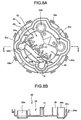
- FIGs. 1 and 2 are exploded perspective views of an outer-mirror tilting apparatus according to the present invention.
- an outer-mirror tilting apparatus 1 is constituted of a holder base 10 which fixes a main body, a housing 40 provided with a housing lid 20 and a housing body 30, a rod driving mechanism 70, and a rod detecting mechanism 100.
- the rod driving mechanism 70 is constituted of a pair of driving rods 50A, 50B, and a pair of driving units 60A and 608.
- the rod detecting mechanism 100 is constituted of a pair of detecting rods 80A and 80B, and a pair of detectors 90A and 90B.
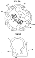
- Figs. 3A to 3C are constitutional examples of a holder base.
- the holder base 10 has a circular plate shape made of synthetic resin and the like, as shown in Figs. 1 and 3 .
- a bearing unit 11 into which a pivot shaft 21 formed on the housing lid 20 of the housing 40 described later is fitted is formed at a central portion of a back face of the holder base 10.
- the bearing unit 11 has a spherical inner face corresponding to the pivot shaft 21 and its root portion is opened with a diameter smaller than the maximum diameter of the pivot shaft 21.
- the bearing unit 11 is formed with a bearing unit opening 11 a extending up to a surface of the holder base 10 in a communicating manner at a position thereof opposed to a housing lid communication hole 21a formed in the housing lid 20 of the housing 40, as described later.
- a pair of driving sockets 12A and 12B, and a pair of detecting sockets 13A and 13B are formed in an annular manner near an outer peripheral edge of the back face of the holder base 10.
- the respective sockets (12A, 12B, 13A, and 13B) are formed on an outer periphery of the bearing unit 11 at intervals of 90°.
- the respective sockets (12A, 12B, 13A, and 13B) have the same shape.
- the pair of driving sockets 12A and 12B have spherical inner faces corresponding to ones of the pair of driving rods 50A, 50B, respectively, and their root portions are opened with diameters smaller than the maximum diameters of the pair of driving rods 50A, 50B.
- the pair of detecting sockets 13A and 13B have spherical inner faces corresponding to ones of the pair of detecting rods 80A and 80B, respectively, and their root portions are opened with diameters smaller than the maximum diameters of the pair of detecting rods 80A and 80B.
- the pair of driving sockets 12A and 12B and the pair of detecting sockets 13A and 13B are formed so as to be opposed to each other via the bearing unit 11. That is, the driving socket 12A and the detecting socket 13A, and the driving socket 12B. and the detecting socket 13B are formed in the holder base 10 such that the bearing unit 11 is interposed therebetween.
- the pair of driving sockets 12A, 12B and the pair of detecting sockets 13A, 13B are formed with slits, respectively.
- the root portions of the respective sockets (12A, 12B, 13A, and 13B) are spread in a pressing manner through the slits so that the respective rods (50A, 50B, 80A, and 80B) can be fitted to the sockets easily.
- Openings for plate spring 14 extending from a surface of the holder base 10 to a back face thereof in a communicating manner are formed between the sockets adjacent to each other along the circumferential direction, namely, between the driving socket 12A and the driving socket 12B, between the driving socket 12B and the detecting socket 13A, between the detecting socket 13A and the detecting socket 13B, and between the detecting socket 13B and the driving socket 12A (four portions in Fig. 3A ).
- a sliding piece 15 projecting from the back face of the holder base 10 is formed on an inner wall face defining the opening for plate spring 14 on an outer peripheral side of the holder base 10.
- a pair of openings for rotation restricting protrusion 16, 16 which communicate from the surface of the holder base 10 to the back face (eight portions in Fig. 3A ) respectively are formed between each of the sockets (12A, 12B, 13A, and 13B) and the bearing unit 11.
- a resilient portion 17 including a pair of resilient pieces is formed between the pair of openings for rotation restricting protrusion 16 and 16 so as to project from the back face of the holder base 10 (four pieces in Fig. 3A ).
- a groove 18 is formed on the surface of the holder base 10.
- the groove 18 is constituted of main grooves 18a formed around the bearing unit 11 and communication grooves 18b communicating from the main grooves 18a to the openings for plate spring 14.
- Engagement pieces for plate spring 19 are formed in the main groove 18a at a position where the bearing unit 11 and each resilient portion 17 are opposed to each other so as to project from the surface of the holder base (four pieces in Fig. 3A ).
- Fig. 1 two plate springs 110A and 110B are mounted on the holder base 10.
- the two plate springs 110A and 110B prevent vibrations between the holder base 10 and the housing 40.
- Figs. 4A and 4B are constitutional examples of a plate spring.
- the plate springs 110A and 110B are formed in a plate shape.
- the plate springs 110A and 110B are respectively formed at their central portions 111 with openings for bearing unit 112 into which the bearing unit 11 projecting from the main groove 18a of the holder base 10 is inserted.
- Each plate spring 110A, 110B has plate spring extending portions 113 and 113 corresponding to the communication grooves 18b of the holder base 10, which are formed by bending both ends of the central portion 111 upward and bending them horizontally.
- end portions of the plate spring extending portions 113 and 113 are bent downward so as to be inserted into the openings for plate spring 14 and 14 of the holder base 10 and turn-back portions 114 are formed at the end portions bent downward.
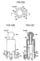
- Figs. 5A, 5B , and Figs. 6A, 6B are constitutional examples of the housing lid 20.
- the housing lid 20 of the housing 40 is made of synthetic resin and the like and is formed in a disc shape.
- the pivot shaft 21 is formed at a central portion of a surface of the housing lid 20.
- the pivot shaft 21 has a spherical distal end, which is fitted into the bearing unit 11 of the holder base 10.
- the pivot shaft 21 has a hollow structure and is formed with a housing lid communication hole 21 a extending or communicating from the distal end to a back face of the housing lid 20.
- a pair of driving rod through holes 22A, 22B and a pair of detecting rod through holes 23A, 23B corresponding to the pair of driving sockets 12A, 12B and the pair of detecting sockets 13A, 13B of the holder base 10 are formed near an outer peripheral edge of the housing lid 20.
- the respective rod through holes (22A, 22B, 23A, and 23B) are formed at intervals of 90° along a circumferential direction of the housing lid 20 near the outer peripheral edge thereof.
- the pair of driving rods 50A, 50B described later are projected from/retracted into the pair of driving rod through holes 22A, 22B of the housing lid 20, namely, from/into the housing 40 by the pair of driving units 60A, 60B.
- the pair of detecting rods 80A, 80B described later are projected from/retracted into the pair of detecting rod through holes 23A, 23B, namely, from/into the housing 40 by tilting of the holder base 10 due to projection/retraction of the pair of driving rods 50A, 50B from/into the housing 40.
- Each of curved protrusions 24 protruding toward the holder base 10 is formed between the rod through holes adjacent to each other along the circumferential direction, that is, the curved protrusions 24 are formed between the driving rod through hole 22A and the driving rod through hole 22B, between the driving rod through hole 22B and the detecting rod through hole 23A, between the detecting rod through hole 23A and the detecting rod through hole 23B, and between the detecting rod through hole 23B and the driving rod through hole 22A.
- the sliding piece 15 of the holder base 10 abuts on the curved protrusion 24 and the former slides on the latter.
- a first annular projection 20a projecting toward the housing body 30 described later is formed at the outer peripheral edge of the housing lid 20.
- Housing temporarily retaining pieces 20b engaged with housing temporarily retaining holes 30b of the housing body 30 described later are formed on the first annular projection 20a at predetermined intervals (eight pieces in Fig. 5A ).
- a second annular projection 20c projecting toward the housing body 30 is formed inside the first annular projection 20a, namely, near an outer peripheral edge on a back face of the housing lid 20, so as to surround the respective rod through holes (22A, 22B, 23A, and 23B).
- a detecting retaining member 25 that retains a detecting connector 95 of a detecting member 93 of a detector 90 described later is formed near the central portion on the back face of the housing lid 20 so as to project toward the housing body 30.
- a pair of rotation restricting protrusions 26 projecting toward the holder base 10 respectively are formed between each rod through hole (22A, 22B, 23A, and 23B) of the housing lid 20 and the pivot shaft 21 (eight pieces in Fig. 5A ). That is, the respective pairs of rotation restricting protrusions 26 are formed at intervals of 90° along an outer periphery of the pivot shaft 21.
- a resilient portion of the holder base 10 is inserted into a space 26a formed between the pair of rotation restricting protrusions 26 in a biased manner.
- the width of the space 26a is set smaller than the width of the pair of resilient pieces constituting the resilient portion 17 of the holder base 10.
- Reference sign 27 denotes a motor fixing member for fixing a motor 64 of a driving unit 70 described later between the housing lid 20 and the housing body 30.
- driving rod sealing members 120 are inserted into the pair of driving rod through holes 22A, 22B, and two retractable portions 132 of a detecting-rod sealing member 130 are inserted into the pair of detecting rod through holes 23A, 23B.
- the driving rod sealing members 120 and the detecting-rod sealing member 130 perform sealing between each rod through hole (22A, 22B, 23A, and 23B) and each rod (50A, 50B, 80A, and 80B) for preventing external water from entering into interior of the housing 40.
- the driving rod sealing members 120 are obtained by forming elastic material such as rubber into a ring-like shape, and they have driving rod openings 121, as shown in Fig. 1 .
- Figs. 7A to 7C are constitutional examples of the detecting-rod sealing member.
- the detecting-rod sealing member 130 is made of elastic material such as rubber, and is constituted of a sealing member main body 131 and two retractable portions 132.
- the sealing member main body 131 is formed in a flat plate shape, it is interposed between the housing lid 20 and the housing body 30 described later, and an area thereof is set so as be able to cover an outer periphery of a detector accommodating portions 36 and detecting rod guiding portions 34A, 34B of the housing body 30 described later.
- the retractable portions 132 projecting so as to oppose to the holder base 10, namely, the pair of detecting rod through holes 23A, 23B of the housing lid 20 are formed at both end portions of the sealing member main body 131.
- the retractable portion 132 is formed in a cylindrical shape with a hollow portion 132a.
- the retractable portion 132 has a bellows-like sectional shape, and it is retractable in a direction of arrow F.
- a detecting rod opening 133 surrounding an outer periphery of the detecting rod 80A or 80B, described later, arranged in the hollow portion 132a is formed at a distal end of the retractable portion 132.
- Reference sign 134. denotes a rod inserting opening
- reference sign 135 denotes a retaining member opening into which the detecting retaining member 25 of the housing lid 20 is inserted.
- Figs. 8A, 8B , and Figs. 9A, 9B are constitutional examples of the housing body.
- the housing body 30 of the housing 40 is made of synthetic resin or the like and is formed in a disc shape.
- a housing body communication hole 31 opposed to the housing lid communication hole 21 a of the housing lid 20 is formed at a central portion of the housing body 30.
- the housing body communication hole 31 communicates from a surface of the housing body 30 to a back face thereof, and a housing communication hole is constituted of the housing body communication hole 31 and the housing lid communication hole 21a. Accordingly, the housing communication hole communicates from the distal end of the pivot shaft 21 of the housing lid 20 up to the back face of the housing 40.
- a first annular projection 30a projecting toward the housing lid 20 is formed at an outer peripheral edge of the housing body 30.
- Housing temporarily retaining holes 30b engaged with housing temporarily retaining pieces 20c of the housing lid 20 are formed on the first annular projection 30a at predetermined intervals (eight pieces in Fig. 8A ).
- a recess portion 32 is formed around the housing body communication hole 31, and a second annular projection 30c projecting toward the housing lid 20 is formed on an outer peripheral edge of the recess portion 32.
- a pair of driving rod guiding portions 33A, 33B corresponding to the pair of driving rod through holes 22A, 22B of the housing lid 20 are formed on the recess portion 32.
- a pair of detecting rod guiding portions 34A, 34B corresponding to the pair of detecting rod through holes 23A, 23B are also formed on the recess portion 32.
- Each of these rod guiding portions (33A, 33B, 34A, and 34B) is cylindrical and is formed so as to project toward the housing lid 20.
- Driving unit accommodating portions 35 which accommodate driving units 60A, 60B driving respective ones of a pair of driving rods 50A, 50B described later are formed near the driving rod guiding portions 33A, 33B on the recess portion 32.
- the driving unit accommodating portions 35 are formed in a V shape so as not to interfere with the housing body communication hole 31.
- a detector accommodating portion 36 which accommodates a detecting member 93 provided with resistors 92 of detectors 90A, 90B described later is formed near the detecting rod guiding portions 34A, 34B.
- Extending portions 34a here are respectively provided on the detecting rod guiding portions 34A, 34B diametrically outward of the detecting rod guiding portions 34A, 34B, namely, on the side of the detector accommodating portion 36.
- the respective extending portions 34a are formed with notches 34b causing the detecting rod guiding portions 34A, 34B to communicate with the detector accommodating portion 36 (refer to Fig. 9B ).
- the respective notches 34b are formed for allowing sliding members 91 of the detectors 90A, 90B fixed to the pair of detecting rods 80A, 80B to slide on the resistors 92 of the detecting member 93 accommodated in the detector accommodating portion 36.
- Drive power source connector receivers 37, 37 which respectively correspond to motors 64, 64 of the driving units 60A, 60B accommodated in the driving unit accommodating portions 35 are formed on a back face of the housing body 30.
- Reference sign 39 denotes a positioning hole into which a positioning protrusion 201 formed on an outer mirror base 200 is inserted (four in Fig. 8A ).
- the rod driving mechanism 70 is constituted of a pair of driving rods 50A, 50B arranged inside the housing 40 and driving units 60A, 60B that drive the pair of driving rods 50A, 50B, respectively.
- Figs. 10A to 10C are constitutional examples of the driving rod.
- the holder base 10 and the main body fixed to the holder base 10 are tilted in left and right directions by the driving rod 50A and the driving unit 60A and in upward and downward directions by the driving rod 50B and the driving unit 60B.
- the pair of driving rods 50A, 50B are made of synthetic resin and the like and have cylindrical shapes with a hollow portion 50a, as shown in Fig. 2 and Figs. 10A to 10C .
- a distal end 50b of each of the pair of driving rods 50A, 50B is formed in a spherical shape.
- Each of the pair of driving rods has a step 50c formed near the distal end 50b.
- a distal end protrusion 50d projecting in a diametrically outward direction of each of the pair of driving rods 50A, 50B is formed at the distal end 50b.
- Each distal end protrusion 50d is formed so as have a width narrower than each of the widths of slits formed on the pair of driving sockets 12A, 12B of the holder base 10.
- Each leg 50e are formed on a lower portion of each of the pair of driving rods 50A, 50B by four slits, not shown.
- a sliding click 50f projecting in a diametrically outward direction of each of the pair of driving rods 50A, 50B is formed on each of these legs 50e.
- the sliding click 50f is provided in an inclined manner to a horizontal direction of each of the pair of driving rods 50A, 50B.
- Reference sign 50g denotes a spring fixing hole for fixing a spring 140 described later in each hollow portion 50a of the pair of driving rods 50A, 50B.
- each of the driving units 60A, 60B is constituted of a first gear 61, a second gear 62, a third gear 63, and a motor 64.
- the first gear 61 is made of synthetic resin or the like, and has a cylindrical shape with a hollow portion 61 a.
- the first gear 61 is formed at an upper portion thereof with a flange 61 b.
- a female screw 61 c screwed with the sliding clicks 50f of each of the pair of driving rods 50A, 50B is formed on an inner wall face of the hollow portion 61 a.
- An external gear 61 d is formed on a side face of the flange 61 b.
- the second gear 62 is formed on upper and lower portions thereof with two different external gears 62a, 62b, and the external gear 62a on the upper portion meshes with the external gear 61 d of the first gear 61, while the external gear 62b on the lower portion meshes with the third gear 63 inserted and fixed to a rotational shaft of the motor 64.
- the external gear 62b of the second gear on the lower portion and the third gear 63 constitute a worm gear mechanism.
- the motor 64 is externally supplied with power from a driving power source connector inserted into the driving power source connector receiver 37 of the housing body 30.
- a rotational shaft, not shown, is rotated by the supplied power, so that the first gear 61 is forward and backward rotated via the third gear 63 inserted and fixed to the rotational shaft and the second gear 62.
- the rod detecting mechanism 100 is constituted of a pair of detecting rods 80A, 80B disposed in the housing 40 and detectors 90A, 90B that detect projection/retraction amounts of the pair of detecting rods 80A, 808 from/into the housing 40.
- Figs. 12A to 12C are constitutional examples of the detecting rod.
- Figs. 13A to 13C are constitutional examples of the detector.
- the detecting rod 80A and the detector 90A detect a tilting angle of the holder base 10 and the main body fixed to the holder base 10 in left and right directions thereof.
- the detecting rod 80B and the detector 90B detect the tilting angle of the holder base 10 and the main body fixed to the holder base 10 in upward and downward directions thereof.
- each of the pair of detecting rods 80A, 80B is made of synthetic resin or the like, and has a cylindrical shape with a hollow portion 80a.
- a distal end 80b of each of the pair of detecting rods 80A, 80B is formed in a spherical shape. Further, a step 80c is formed near the distal end 80b.
- Each leg 80d are formed on a lower portion of each of the pair of detecting rods 80A, 80B by four slit, not shown.
- Engagement clicks 80e projecting in a diametrically outward direction of each of the pair of detecting rods 80A, 80B are formed on each leg 80d.
- a sliding member fixing portion 80f with a recessed sectional shape in a horizontal direction of each of the pair of detecting rods 80A, 80B is formed on one of the engagement clicks 80e.
- the sliding member fixing portion 80f is formed at a portion of the engagement click 80e opposed to an inner peripheral face of one of the pair of detecting rod guiding portions 34A, 34B, and it is fixed with one of sliding members 91, 91 of the detectors 90A, 90B described later.
- Reference sign 80g denotes a spring fixing hole for fixing a spring 140 described later in the hollow portion 80a of one of the pair of detecting rods 80A, 80B.
- each of the detectors 90A, 90B is constituted of a sliding member 91 and a resistor 92.
- the sliding member 91 is made of metal material with electrical conductivity or the like, and it includes a plurality of sliding pieces 91 a with resilience (four pieces in Fig. 13A ).
- Each resistor 92 of each detector 90A, 90B is provided on one detecting member 93 made of plastic plate or the like, namely it is printed thereon. Accordingly, the number of parts for the outer mirror that can detect the tilting angle of the main body can further be reduced, and reduction in the number of assembling steps and reduction in manufacturing cost can be achieved.
- a plurality of voltage-dividing resistors 94 for each resistor 92 are provided on the detecting member 93 (four pieces in Fig. 13C ).
- the voltage-dividing resistor 94 is for setting electric output varying according to sliding of the sliding piece 91 a of the sliding member 91 on the resistor 92, namely, change of voltage to a predetermined change width.
- the detecting connector 95 that outputs electric outputs of the respective resistors 92 is provided at a central portion on a face of the detecting member 93 opposed to a face where the resistors 92 are provided.
- a plurality of connecting terminals 96a to 96d for electrical connection with an external connector, not shown, are provided on the detecting connector 95 (four pieces in Fig. 13C ).
- the connecting terminals 96a, 96b here are for externally outputting an electrical output of the detector 90A varying when the tilting angle of the holder base 10 are changed in a left or right direction.
- the connecting terminals 96c, 96d are for externally outputting an electrical output of the detector 90B varying when the tilting angle of the holder base 10 are changed in an upward or downward direction.
- each rod (50A, 50B, 80A, and 80B) is inserted with a spring 140 which is a resilient member.
- This spring prevents vibrations from generated between each rod (50A, 50B, 80A, and 80B) and the housing 40.
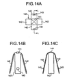
- Figs. 14A to 14C are constitutional examples of the spring.
- the spring 140 is made of a metal member having resilience, and it is constituted of a spring main body 141 and biasing portions 142.
- the biasing portions 142 extend from four sides of the spring main body 141. That is, the spring 140 has four biasing portions 142.
- the widths of the biasing portions 142, 142 opposed to each other are set to be larger than the widths of the pair of opposed legs 50e, 50e and a pair of opposed legs 80d, 80d of the respective rods (50A, 50B, 80A, and 80B).
- Spring fixing protrusions 143, 143 corresponding to the spring fixing holes 50g, 80g of each rod (50A, 50B, 80A, and 80B) are formed in the pair of opposed biasing portions 142, 142.
- FIGs. 15A and 15B are perspective views of an outer-mirror tilting apparatus during assembling thereof.
- Fig. 16 is a plan view of a portion of the outer-mirror tilting apparatus indicated with a circle M in Fig. 15B .
- Fig. 17 is a perspective view of an assembled outer-mirror tilting apparatus.
- Fig. 18 is a sectional view of the outer-mirror tilting apparatus taken along line N-N in Fig. 17 .
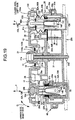
- Fig. 19 is a sectional view of the outer-mirror tilting apparatus taken along line O-O in Fig. 17 .
- each resilient portion 17 of the holder base 10 is inserted in the space 26a between each pair of rotation restricting protrusions 26 of the housing lid 20.
- the resilient portion-17 resiliently deforms to abut on the rotation restricting protrusions 26 in a biased state.
- the plate springs 110A, 110B are inserted into the groove 18 of the holder base 10 in an overlapped state thereof in directions orthogonal to each other.
- the inserted plate springs 110A, 110B are engaged with the engagement pieces for plate spring 19.
- respective turn back portions 114, 114 of the plate springs 110A, 110B are inserted into the openings for plate spring 14 of the holder base 10, and they abut on the sliding pieces 15 in a biased state.
- the sliding piece 15 is resiliently deformed by the turn back portion 114 on which the sliding piece 15 abuts in the biased state, so that the sliding piece 15 is abutted on the curved protrusion 24 of the housing lid 20 (refer to Fig. 18 ).
- the holder base 10 is tilted about the pivot shaft 21 of the housing lid 20, namely, it is tilted to the housing 40, vibrations between the housing lid 20, or the housing 40, and the holder base 10 can be prevented from occurring.
- two driving rod sealing members 120 are respectively inserted into the pair of driving rod through holes 22A, 22B of the housing lid 20 from the back face of the housing lid 20.
- the two retractable portions 132 of one detecting-rod sealing member 130 are respectively inserted into the pair of detecting rod through holes 23A, 23B of the housing lid 20 from the back face of the housing lid 20.
- the rod driving mechanism 70 is disposed in the housing body 30 of the housing 40. Specifically, each third gear 63 is inserted into a rotational shaft, not shown, of each motor 64 to be fixed thereto. Next, the motor 64 and the second gear 62 constituting the driving unit 60A, and the motor 64 and the second gear 62 constituting the driving unit 60B are respectively accommodated in the respective driving unit accommodating portion 35. At that time, each second gear 62 is rotatably supported by a gear shaft, not shown, inside the housing body 30. The external gear 62b at the lower portion of the second gear 62 and the third gear 63 are meshed with each other.
- the respective first gears 61 of the driving units 60A, 60B are respectively inserted into the pair of driving rod guiding portions 33A, 33B.
- the respective first gears 61 are rotatably supported by the pair of driving rod guiding portions 33A, 33B.
- the external gear 61 d of each first gear 61 and the external gear 62a at the upper portion of each second gear 62 are meshed with each other.
- the respective springs 140 are respectively inserted into the hollow portions 50a of the pair of driving rods 50A, 50B.
- the respective sliding clicks 50f of the pair of driving rods 50A, 50B are screwed to the female screws 61 c of the respective first gears 61 of the driving units 60A, 60B.
- the widths of the opposed biasing portions 142, 142 of each spring 140 are larger than those of the pair of opposed legs 50e, 50e of each of the pair of driving rods 50A, 50B, as shown in Fig.
- the respective legs 50e resiliently deform in a diametrically outward direction of each of the pair of driving rods 50A, 50B, so that the respective sliding clicks 50f abut on the female screw 61 c of the first gear 61, namely, an inner peripheral face of the first gear 61 in a biased state.
- forces for projecting/retracting the pair of driving rods 50A, 50B from/into the housing 40 are increased so that vibrations generated between the housing 40 (the driving rod guiding portions 33A, 33B) and the pair of driving rods 50A, 50B can be reduced.
- the rod detecting mechanism 100 is disposed inside the housing body 30 of the housing 40. Specifically, the detecting member 93 provided with the respective resistors 92 for the detectors 90A, 90B is received in the detector accommodating portion 36 of the housing body 30. At that time, as shown in Fig. 18 , the detecting connector 95 provided on the detecting member 93 is disposed at a position opposed to the external connector receiver 38 formed on the housing body 30. The connection terminals 96a to 96d of the detecting connector 95 project in the external connector receiver 38.
- the respective springs 140 are inserted into the hollow portions 50a of the pair of detecting rods 80A, 80B.
- the respective sliding members 91 of the detectors 90A, 90B are fixed to the respective sliding member fixing portions 80f of the pair of detecting rods 80A, 80B.
- the pair of detecting rods 80A, 80B are respectively inserted into the pair of detecting rod guiding portions 34A, 34B.
- the width between the opposed biasing portions 142, 142 of each spring 140 is larger than width between the pair of the opposed legs 80d, 80d of the pair of detecting rods 80A, 80B, as shown in Fig.
- the respective legs 80d resiliently deform in the diametrically outward directions of the pair of detecting rods 80A, 80B so that the respective engagement clicks 80e abut on the inner peripheral faces of the detecting rod guiding portions 34A, 34B in a biased state.
- vibrations generated between the housing 40 and the pair of detecting rods 80A, 80B can be reduced, vibrations of the holder base 10 where the detecting sockets 13A, 13B are tiltably fitted on the respective distal ends 80b of the pair of detecting rods 80A, 80B can be reduced. Thereby, vibrations of the main body fixed to the holder base 10 can be reduced, so that visibility of the main body can be prevented from lowering.
- the respective sliding members 91 fixed to the respective sliding member fixing portions 80f abut on the respective resistors 92 provided on the detecting member 93. Accordingly, as shown in Fig. 19 , when the pair of detecting rods 80A, 80B move in a direction P of projection/retraction thereof, the respective sliding members 91 slide on the respective resistors 92. That is, the detectors 90A, 90B constitute a sliding type variable resistor. Thereby, the projection/retraction amounts of the pair of detecting rods 80A, 80B cause change of a resistance value, namely, change of a voltage, so that the tilting angle of the main body fixed to the holder base 10 can be easily and simply detected.
- the respective sliding member fixing portions 80f of the pair of detecting rods 80A, 80B are disposed at the extending portions 34a of the pair of detecting rod guiding portions 34A, 34B.
- the both ends 34c, 34c of the notches 34b of the respective extending portions 34a abut on the both ends 80h, 80h of faces of the respective sliding member fixing portions 80f on which the sliding members 91 are fixed. That is, one portions of the respective sliding member fixing portions 80f abut on inner peripheral faces of the pair of detecting rod guiding portions 34A, 34B having the extending portions 34a.
- biasing forces of the respective springs 140 which are resilient members are transmitted from the sliding member fixing portions 80f of the engagement clicks to inner peripheral faces of the pair of detecting rod guiding portions 34A, 34B. That is, biasing forces for sliding the sliding members 91 fixed to the respective sliding member fixing portions 80g on the respective resistors 92 are not influenced by the biasing forces of the springs 140. Accordingly, the respective sliding members 91 can slide on the respective resistors 92 accurately corresponding to the projection/retraction amounts of the pair of detecting rods 80A, 80B, so that detection accuracy of the tilting angle of the main body fixed to the holder base 10 can be prevented from lowering
- both side faces of the respective sliding member fixing portions 80f abut on both side faces of the respective extending portions 34a.
- the respective sliding members 91 can be prevented from being damaged due to that the pair of detecting rods 80A, 80B rotates inside the pair of detecting rod guiding portions 34A, 34B, respectively.
- the pair of detecting rods 80A, 80B are prevented from rotating to cause the positions of the respective sliding members 91 to the respective resistors 92 to change. Accordingly, the detection accuracy of the tilting angle of the main body fixed to the holder base is further prevented from lowering.
- the respective distal ends 50b of the pair of driving rods 50A, 50B are respectively fitted into the pair of driving sockets 12A, 12B via the respective driving rod openings 121 of the two driving rod sealing members 120 and the pair of driving rod through holes 22A, 22B of the housing lid 20.
- the distal ends 80b of the pair of detecting rods 80A, 80B are respectively fitted into the pair of detecting sockets 13A, 13B via the respective detecting rod openings 133 of the detecting-rod sealing member 130 and the pair of detecting rod through holes 23A, 23B of the housing lid 20.
- the respective distal end protrusions 50d of the pair of driving rods 50A, 50B are inserted into slit, not shown, of the pair of driving sockets 12A, 12B, so that the rotations of the pair of driving rods 50A, 50B are restricted. Since the respective distal ends 80b of the pair of detecting rods 80A, 80B are tiltably fitted into the pair of detecting sockets 13A, 13B formed on the tilting holder base 10, foreign matters are prevented from entering between the holder base 10 and the housing lid 20. Thereby, the followabilies of the pair of detecting rods 80A, 80B to tilting of the holder base 10 can be prevented from deteriorating, so that the detection accuracy of the tilting angle of the main body fixed to holder base 10 can be prevented from lowering
- the housing body 30 is temporarily retained with the housing lid 20. That is, the housing temporarily retaining pieces 20b of the housing lid 20 are inserted into the housing temporarily retaining holes 30b of the housing body 30. Thereby, the housing lid 20 is retained to the housing body 30.
- the first annular projection 30a of the housing body 30 and the second annular projection 30c abut on the first annular projection 20a of the housing lid 20 and the second annular projection 20c, respectively, so that positioning between the housing lid 20 and the housing body 30 is conducted.
- the sealing member main body 131 of the detecting-rod sealing member 130 abuts on the housing lid 20 and the housing body 30, and the detecting rods 80A, 80B are disposed in the hollow portions 132a of the respective retractable portions 132, so that a sealing structure of the housing 40 is constituted. That is, the back face of the housing lid 20, specifically, opposed to the pair of detecting rod guiding portions 34A, 34B and the detector accommodating portion 36 of the housing body 30 is covered with the sealing member main body 131, so that the sealing member main body 131 is interposed between the housing lid 20 and the housing body 30.
- Outer peripheries of the pair of detecting rods 80A, 80B are surrounded by the detecting rod openings 133 formed in the retractable portions 132. Accordingly, seating can be conducted between each of the pair of detecting rod through holes 23A, 23B and corresponding one of the pair of detecting rods 80A, 80B which constitute a route through which water enters from the outside, and between the housing lid 20 and the housing body 30 by one detecting-rod sealing member 130 without influence of each detecting rod opening 133 on the each of the pair of detecting rods 80A, 80B projecting from/retracting into the pair of detecting rod through holes 23A, 23B of the housing lid 20.
- the number of parts for sealing the housing 40 having a plurality of routes through which water enters from the outside can be reduced, so that reduction of the number of assembling steps and reduction of manufacturing cost can be achieved. Since the detecting-rod sealing member 130 is not interposed between the housing lid 20 and a portion of the housing body 30 where water may enter from the outside, the sealed structure of the housing can be reduced in size and reduction of the manufacturing cost can be achieved.
- the respective retractable portions 132 cover the pair of detecting rods 80A, 80B, namely, the pair of detecting rods 80A, 80B are disposed in the hollow portions 132a of the respective retractable portions 132, even if the pair of detecting rods 80A, 80B move in the projecting/retracting directions P, the amounts of projection/retraction can be absorbed by the respective retractable portions 132. Accordingly, the respective detecting rod openings 133 of the detecting-rod sealing member 130 can be suppressed from moving from the positions of the outer peripheries of the pair of detecting rods 80A, 80B surrounded by the respective detecting rod openings 133.
- the detecting rod openings 133 can be suppressed from sliding on the outer peripheries of the pair of detecting rods 80A, 80B in the projecting/retracting directions P of the detecting rods 80A, 80B. Water can be prevented from entering between each detecting rod opening 133 and corresponding one of the pair of detecting rods 80A, 80B by the sliding. Thereby, detection accuracy of the tilting angle of the main body fixed to the holder base 10 obtained by the detectors 90A, 90B can be prevented from lowering.
- the respective detecting rod openings 133 cover the respective steps 80c of the pair of detecting rods 80A, 80B, the respective detecting rod openings 133 of the detecting-rod sealing member 130 can be restricted from moving beyond the respective steps 80c toward the housing 40. That is, since the respective detecting rod openings 133 are prevented from sliding beyond the respective steps 80c toward the housing 40, water can be prevented from entering between the respective detecting rod openings 133 and the pair of detecting rods 80A, 80B. Thereby, detection accuracy of the tilting angle of the main body fixed to the holder base 10 obtained by the detectors 90A, 90B can be prevented from lowering.
- the outer-mirror tilting apparatus 1 is mounted on the outer mirror base 200.
- the positioning holes 39 of the housing body 30 of the housing 40 is inserted into the positioning protrusions 201 formed at predetermined portions of the outer mirror base 200.
- the outer-mirror tilting apparatus 1 is positioned to the outer mirror base 200.
- a screw (refer to Fig. 1 ) 150 which is a housing fixing member is screwed and inserted from the bearing unit opening 11 a of the pivot shaft 11 of the holder base 10 to a housing communication hole constituted of the housing lid communication hole 21a of the housing lid 20 and the housing body communication hole 31 of the housing body 30.
- the housing lid 20 and the housing body 30 can be fixed by one fixing member.
- a distal end of the screw 150 which has been protruded beyond the back face of the housing 40 is then screwed and inserted to a screw opening 202 formed in the outer mirror base 200.
- the outer-mirror tilting apparatus 1 is fixed to the outer mirror base 200. Accordingly, fixation of the outer-mirror tilting apparatus 1 to the outer mirror base 200 can securely be performed by one screw 150. Thereby, the number of parts for the outer mirror including the outer-mirror tilting apparatus 1 can be reduced, and reduction of the number of assembling steps or reduction of manufacturing cost can be achieved.
- the housing or the holder base can further be reduced in size, as compared with a conventional way of fixing at an outer periphery of the housing 40. Thereby, size reduction of the outer-mirror tilting apparatus 1 can be achieved. Further, since the screw 150 is screwed and inserted to the housing communication hole from the bearing unit opening 11 a of the holder base 10, the outer-mirror tilting apparatus 1 can be simply and easily fixed to the outer mirror base 200 by the screw 150 after the pivot shaft 21 of the housing lid 20 of the housing 40 is fitted to the bearing unit 11 formed on the holder base 10.
- Driving power source connectors are respectively inserted into the respective driving power source connector receivers 37 of the housing body 30 (refer to Fig. 9A ).
- the driving power source connectors supply driving power to the respective motors 64 of the driving units 60A, 60B from a battery mounted on a vehicle or the like via a tilting controller, not shown.
- an external connector is inserted into the external connector receiver 38 of the housing body 30, and a connecting terminal receiver, not shown, of the external connector and connecting terminals 96a to 96d of the detecting connector 95 of the detecting member 93 are connected to each other.
- the detecting member 93 as well as the detecting connector 95 can be restricted from moving in the projecting/retracting directions P of the pair of detecting rods 80A, 80B. That is, when the external connector is attached to/detached from the detecting connector 95 (the external connector receiver 38), the detecting member 93 provided with the detecting connector 95 can prevent the pair of detecting rods 80A, 80B from moving in the projecting/retracting directions P. Accordingly, the respective sliding members 91 provided on the pair of detecting rods 80A, 80B can be prevented from deviating from the respective resistors 92 provided on the detecting member 93.
- the holder base 10 When the driving rod 50A moves in the direction of projecting from the housing 40, the holder base 10 whose driving socket 12A is fitted to the distal end 50b of the driving rod 50A is tilted about the pivot shaft 21 of the housing lid 20 in a direction (a leftward direction) of the directions of arrow Q in which a distance between the driving socket 12A of the holder base 10 and the housing 40 becomes wider than a distance between the detecting socket 13A and the housing 40. Thereby, the main body fixed to the holder base 10 is tilted to the left side to a traveling direction of the vehicle (refer to Fig. 19 ).
- the detecting rod 80A When the holder base 10 is tilted to the left side, the detecting rod 80A whose distal end 80b is fitted to the detecting socket 13A of the holder base 10 moves in a direction of retracting into the housing 40 of projecting/retracting directions P.
- the detector 90A detects a projecting/retracting amount of the detecting rod 80A. That is, the sliding member 91 fixed to the detecting rod 80A slides on the resistor 92 provided on the detecting member 93 in the direction of retracting into the housing 40, so that a change in a detected voltage of a power source supplied from the external connector, not shown, for example, a voltage change to a plus side is detected.
- the change of the voltage is output to the tilting controller, not shown, via the detecting connector 95 and the external connector.
- the driving rod 50A moves in a direction of retracting into the housing 40 of the projecting/retracting directions P.
- the holder base 10 is tilted about the pivot shaft 21 of the housing lid 20 in a direction (a rightward direction) of the directions of arrow Q in which a distance between the driving socket 12A of the holder base 10 and the housing 40 is made narrower than a distance between the detecting socket 13A and the housing 40.
- the main body fixed to the holder base 10 is tilted to the right side to the traveling direction of the vehicle (refer to Fig. 19 ).
- the detecting rod 80A moves in a direction projecting from the housing 40 of the projecting/retracting directions P, so that the sliding member 91 slides on the resistor 92 in the above direction, and a change of a detected voltage of the power source, for example, the voltage change to the minus side is detected.
- the change of the voltage is output to the tilting controller, not shown.
- the holder base 10 When the driving rod 50B moves in the projecting direction, the holder base 10 whose driving socket 12B is fitted to the distal end 50b of the driving rod 50B is tilted about the pivot shaft 21 of the housing lid 20 in a direction (a downward direction) of the directions of arrow Q in which a distance between the driving socket 12B of the holder base 10 and the housing 40 becomes wider than a distance between the detecting socket 13B and the housing 40.
- the main body fixed to the holder base 10 is tilted downwardly to the traveling direction of the vehicle (refer to Fig. 19 ).
- the detecting rod 80B When the holder base 10 is tilted downwardly, the detecting rod 80B whose distal end 80b is fitted to the detecting socket 13B of the holder base 10 moves in a direction of retracting into the housing 40 of the projecting/retracting directions P.
- the detector 90B detects the projecting/retracting amount of the detecting rod 80B. That is, the sliding member 91 fixed to the detecting rod 80B slides on the resistor 92 provided on the detecting member 93 in the retracting direction, so that change of a detected voltage of a power supplied from the external connector, not shown, for example, the voltage change to the plus side is detected.
- the change of the voltage is output to the tilting controller, not shown, via the detecting connector 95 and the external connector.
- the driving rod 50B moves in a direction of retracting into the housing 40 of the projecting/retracting directions P.
- the driving rod 50B moves in the retracting direction
- the holder base 10 is tilted about the pivot shaft 21 of the housing lid 20 in a direction (an upward direction) of the directions of arrow Q in which a distance between the driving socket 12B of the holder base 10 and the housing 40 becomes narrower than a distance between the detecting socket 13B and the housing 40.
- the main body fixed to the holder base 10 is tilted upwardly to the traveling direction of the vehicle (refer to Fig. 19 ).
- the detecting rod 80B moves in a direction of projecting from the housing 40 of the projecting/retracting directions P, so that the sliding member 91 slides on the resistor 92 in the projecting direction, and change of a detected voltage of the power source, for example, the voltage changes to the minus side is detected.
- the change of the voltage is output to the tilting controller, not shown.
- the outer-mirror tilting apparatus 1 is mounted on the outer mirror on the left side, but the outer-mirror tilting apparatus 1 may be constituted similarly or identically to the above to be mounted on an outer mirror on a right side.
- the outer mirror titling device may be mounted in a state that it is rotated by an angle of 90° from the state that the outer-mirror tilting apparatus is mounted on the outer mirror on the right side.
- the tilting controller is constituted such that the holder base 10 is tilted by the rod driving mechanism 70 in an upward or downward direction and in a left or right direction based on the tilting angle of the holder base 10 in the upward or downward direction and in the left or right direction, which is stored in the tilting controller, the rod detecting mechanism 100 detects the stored tilting angle of the holder base 10 in the upward or downward direction and in the left or right direction, determination is made as to whether the detected tilting angle has reached the stored tilting angle, and the rod driving mechanism 70 is stopped based on the determination.
- the present invention is not limited to such a tilting controller, but such a configuration may be employed that the holder base 10 is titled by the rod driving mechanism 70 in an upward or downward direction and in a left or right direction based on any tilting angle in the upward or downward direction and in the left or right direction which is input from an input unit provided in interior of the vehicle by a driver riding on the vehicle.
- the outer-mirror tilting apparatus 1 is provided inside the housing 40 with the rod driving mechanism 70 and the rod detecting mechanism 100, the rod driving mechanism 70 that tilts the main body fixed to the holder base 10 and the rod detecting mechanism 100 can be integrated into a single unit. Thereby, the number of parts for the outer mirror that can detect the tilting angle of the main body can be reduced and the number of assembling steps or manufacturing cost can be reduced.
Landscapes
- Engineering & Computer Science (AREA)
- Mechanical Engineering (AREA)
- Multimedia (AREA)
- General Engineering & Computer Science (AREA)
- Physics & Mathematics (AREA)
- General Physics & Mathematics (AREA)
- Rear-View Mirror Devices That Are Mounted On The Exterior Of The Vehicle (AREA)
- Telescopes (AREA)
Claims (11)
- Dispositif d'inclinaison d'un rétroviseur extérieur, comprenant :une base de support (10) qui se fixe à un corps principal d'un rétroviseur extérieur ;un boîtier (40) qui est ajusté sur une structure formant palier (11) de la base de support (10), le boîtier (40) présentant un axe de pivotement supportant la base de support d'une manière inclinable ;un mécanisme de commande à tiges (70) qui comporteune paire de tiges de commande (50A, 50B) dont les extrémités distales sont ajustées dans une première douille de commande et une deuxième douille de commande, prévues sur la base de support (10), pour incliner la base de support (10), en direction verticale et en direction horizontale, respectivement ; etune unité de commande (60A, 60B) qui fait sortir/rentrer chacune des deux tiges de commande (50A, 50B) hors du/dans le boîtier (40) ; etun mécanisme de détection à tiges (100) qui comporteune paire de tiges de détection (80A, 80B) positionnées de façon à être en vis-à-vis des deux tiges de commande (50A, 50B), de l'autre côté de l'axe de pivotement, et à sortir du/rentrer dans le boîtier (40), en correspondance avec l'inclinaison de la base de support (10) dans la direction verticale et dans la direction horizontale, respectivement ; etun détecteur (90A, 90B) qui détecte l'angle d'inclinaison de la base de support (10) à partir des amplitudes de sortie/rentrée des deux tiges de détection (80A, 80B), détecteur comportantun élément coulissant (91) qui est fixé à chacune des deux tiges de détection (80A, 80B) ;et une résistance (92) qui est logée dans le boîtier (40) et dont la sortie électrique varie, à partir du coulissement de l'élément coulissant (91), en fonction des amplitudes de déplacement sortie/rentrée des deux tiges de détection (80A, 80B) hors du/dans le boîtier (40) ; etun élément de détection (93), la résistance (92) étant alors formée sur l'élément de détection (93)caractérisé en ce que
l'élément de détection (93) présente un connecteur de détection (95), qui délivre à l'extérieur la sortie électrique de la résistance (92), et qui est connecté à un connecteur externe par une face arrière du boîtier (40), et
le boîtier (40) comporte un élément de retenue (25) pour le système de détection, qui retient le connecteur de détection (95), l'élément de retenue (25) pour le système de détection étant formé en un emplacement opposé au connecteur de détection (95). - Dispositif d'inclinaison d'un rétroviseur extérieur selon la revendication 1, caractérisé en ce que
le boîtier (40) présente un orifice de communication (31) s'étendant d'une extrémité distale de l'axe de pivotement jusqu'à la face arrière du boîtier (40), et
le boîtier (40) est fixé à une base du rétroviseur extérieur, par un élément de fixation de boîtier inséré, par l'orifice de communication (31) du boîtier, jusqu'à la base du miroir extérieur. - Dispositif d'inclinaison d'un rétroviseur extérieur selon la revendication 2, caractérisé en ce que
la structure formant palier (11) présente une ouverture (11a) qui s'étend jusqu'à une surface de la base de support (10), l'ouverture (11a) de la structure formant palier étant réalisée en un emplacement situé en vis-à-vis de l'orifice de communication (31) du boîtier. - Dispositif d'inclinaison d'un rétroviseur extérieur selon l'une au moins des revendications précédentes, caractérisé en ce que
la base de support (10) comporte une paire de douilles de détection (13a, 13b), et
les extrémités distales des deux tiges de détection (80A, 80B) sont respectivement ajustées dans les deux douilles de détection (13a, 13b). - Dispositif d'inclinaison d'un rétroviseur extérieur selon l'une au moins des revendications précédentes, caractérisé en ce que
une paire de parties de guidage de tige de détection (33A, 33B) est formée à l'intérieur du boîtier (40),
chacune des deux tiges de détection (80A, 80B) comporte un cliquet de venue en prise, glissant sur des faces périphériques intérieures des deux parties de guidage de tige de détection (33A, 33B), dans les directions de déplacement sortant/rentrant des deux tiges de détection (80A, 80B), et
le cliquet de venue en prise est sollicité dans une direction diamétralement vers l'extérieur d'une tige de détection correspondante, par un élément élastique fixé sur l'intérieur de la tige de détection. - Dispositif d'inclinaison d'un rétroviseur extérieur selon la revendication 5, caractérisé en ce que
l'élément coulissant (91) est fixé à une partie de fixation d'élément coulissant, formée sur le cliquet de venue en prise et placée en vis-à-vis de faces périphériques intérieures des parties de guidage de tige de détection (33A, 33B),
les parties de guidage de tige de détection (33A, 33B) sont dotées de rainures (34b) pour permettre à l'élément coulissant (91) de coulisser sur la résistance (92), et
une zone des parties de fixation d'élément coulissant (80f) établit un contact avec une surface périphérique intérieure des parties de guidage de tige de détection (33A, 33B). - Dispositif d'inclinaison d'un rétroviseur extérieur selon la revendication 6, caractérisé en ce que
les rainures (34b) sont ménagées sur des parties prolongatrices (34a), formées dans une direction diamétralement vers l'extérieur des parties de guidage de tige de détection (33A, 33B), et
la partie de fixation d'élément coulissant (80f), avec l'élément coulissant (91), est disposée sur les parties prolongatrices (34a). - Dispositif d'inclinaison d'un rétroviseur extérieur selon l'une au moins des revendications précédentes, caractérisé en ce que le boîtier (40) comporte
un couvercle de boîtier (20) sur lequel sont formées une paire d'orifices traversants pour tige de détection et une paire d'orifices traversants pour tige de commande ; et
un corps de boîtier (30) dans lequel sont logés le mécanisme de commande à tiges et le mécanisme de détection à tiges,
un élément d'étanchéité (130) pour les tiges de détection étant interposé entre le couvercle de boîtier (20) et le corps de boîtier (30), l'élément d'étanchéité (130) pour les tiges de détection couvrant une surface de dos du couvercle de boîtier (20), et
une ouverture (133) pour tige de détection, qui entoure les périphéries extérieures des deux tiges de détection (80A, 80B), est formée sur l'élément d'étanchéité (130) pour les tiges de détection, en un emplacement situé en vis-à-vis des trous traversants pour tige de détection. - Dispositif d'inclinaison d'un rétroviseur extérieur selon la revendication 8, caractérisé en ce que le corps de boîtier (30) comporte
la paire de parties de guidage de tige de détection (33A, 33B) à travers lesquelles les deux tiges de détection (80A, 80B) coulissent dans les directions de déplacement sortant/rentrant ; et
une partie de logement de détecteur (36) qui abrite le détecteur (90A, 90B), et
l'élément d'étanchéité (130) pour les tiges de détection est interposé entre le couvercle de boîtier (20), les parties de guidage de tige de détection (33A, 33B) et la partie de logement de détecteur (36). - Dispositif d'inclinaison d'un rétroviseur extérieur selon la revendication 8 ou 9, caractérisé en ce que
l'élément d'étanchéité (130) pour les tiges de détection présente une partie rétractable (132) de la forme d'un soufflet, faisant saillie des orifices traversants pour tige de détection vers la base de support (10), et
l'ouverture (133) pour tige de détection est formée à une extrémité distale de la partie rétractable (132). - Dispositif d'inclinaison d'un rétroviseur extérieur selon l'une au moins des revendications 8 à 10, caractérisé en ce que
chacune des deux tiges de détection (80A, 80B) présente une partie butoir (50c) à proximité de l'extrémité distale, et
l'ouverture (133) pour tige de détection est formée de façon à couvrir la partie butoir (50c).
Applications Claiming Priority (8)
| Application Number | Priority Date | Filing Date | Title |
|---|---|---|---|
| JP2003194987 | 2003-07-10 | ||
| JP2003194989 | 2003-07-10 | ||
| JP2003194990A JP4259213B2 (ja) | 2003-07-10 | 2003-07-10 | アウターミラー傾動装置 |
| JP2003194988 | 2003-07-10 | ||
| JP2003194989A JP2005028959A (ja) | 2003-07-10 | 2003-07-10 | ロッド検出機構 |
| JP2003194990 | 2003-07-10 | ||
| JP2003194988A JP4259212B2 (ja) | 2003-07-10 | 2003-07-10 | ハウジングの密閉構造 |
| JP2003194987A JP2005028957A (ja) | 2003-07-10 | 2003-07-10 | アウターミラー傾動装置 |
Publications (3)
| Publication Number | Publication Date |
|---|---|
| EP1495912A2 EP1495912A2 (fr) | 2005-01-12 |
| EP1495912A3 EP1495912A3 (fr) | 2005-07-27 |
| EP1495912B1 true EP1495912B1 (fr) | 2009-03-25 |
Family
ID=33458985
Family Applications (1)
| Application Number | Title | Priority Date | Filing Date |
|---|---|---|---|
| EP04015685A Expired - Lifetime EP1495912B1 (fr) | 2003-07-10 | 2004-07-02 | Dispositif d'inclinaison d'un rétroviseur extérieur |
Country Status (5)
| Country | Link |
|---|---|
| US (1) | US7334906B2 (fr) |
| EP (1) | EP1495912B1 (fr) |
| KR (1) | KR100582936B1 (fr) |
| CN (1) | CN1318238C (fr) |
| DE (1) | DE602004020151D1 (fr) |
Families Citing this family (16)
| Publication number | Priority date | Publication date | Assignee | Title |
|---|---|---|---|---|
| NL1027557C2 (nl) * | 2004-11-22 | 2006-05-23 | Eaton Automotive Bv | Spiegelverstelmechanisme, in het bijzonder voor een buitenspiegel voor een motorvoertuig. |
| KR100600926B1 (ko) * | 2005-05-26 | 2006-07-13 | 주식회사 쉐프네커 풍정 | 구동력을 향상시킨 자동차용 전동식 아웃사이드미러의 미러구동장치 |
| KR100623331B1 (ko) * | 2005-05-26 | 2006-09-13 | 주식회사 쉐프네커 풍정 | 고정축 출력전압 특성을 향상시킨 자동차용 전동식아웃사이드미러의 미러 구동장치 |
| KR100694441B1 (ko) * | 2005-12-10 | 2007-03-12 | 주식회사 쉐프네커 풍정 | 조정가이드의 밀착력을 향상시킨 자동차용 전동식아웃사이드미러의 위치 검출장치 |
| ATE528170T1 (de) * | 2009-01-14 | 2011-10-15 | Magna Auteca Ag | Antrieb für ein zu verstellendes bauteil |
| EP2208641B1 (fr) * | 2009-01-14 | 2011-11-02 | Magna Auteca AG | Entraînement pour un composant qui est à ajuster |
| WO2011058907A1 (fr) | 2009-11-10 | 2011-05-19 | 株式会社ミツバ | Dispositif de réglage angulaire de surface de miroir |
| JP5775263B2 (ja) * | 2010-02-08 | 2015-09-09 | 株式会社東海理化電機製作所 | 車両用ミラー装置 |
| JP5710227B2 (ja) * | 2010-11-30 | 2015-04-30 | 株式会社東海理化電機製作所 | 車両用ミラー装置 |
| JP6051499B2 (ja) * | 2010-12-14 | 2016-12-27 | 市光工業株式会社 | 車両用アウトサイドミラー装置 |
| JP6133541B2 (ja) * | 2012-02-13 | 2017-05-24 | 株式会社東海理化電機製作所 | 車両用ミラー装置 |
| JP6040049B2 (ja) | 2013-02-20 | 2016-12-07 | 株式会社村上開明堂 | 車両用ミラー装置の鏡面角度検出装置のシール構造および車両用ミラー装置 |
| JP6678059B2 (ja) * | 2016-03-31 | 2020-04-08 | 株式会社村上開明堂 | 視認装置の視認角度調整機構 |
| CN106427789A (zh) * | 2016-08-28 | 2017-02-22 | 宁波精成车业有限公司 | 记忆式汽车后视镜镜面驱动器 |
| CN106711676B (zh) * | 2016-11-30 | 2020-02-07 | 北京金风科创风电设备有限公司 | 电连接器、电容放电器及放电方法 |
| CN106697137B (zh) * | 2016-12-31 | 2019-08-27 | 张玉莲 | 减震机构 |
Family Cites Families (25)
| Publication number | Priority date | Publication date | Assignee | Title |
|---|---|---|---|---|
| FR2526737B1 (fr) * | 1982-05-13 | 1986-04-25 | Manzoni Stephane | Dispositif limiteur de couple pour mecanisme de commande d'un miroir de retroviseur |
| US4606616A (en) * | 1983-05-18 | 1986-08-19 | Parker Douglas I | Microscopes |
| US4678295A (en) * | 1985-04-05 | 1987-07-07 | Magna International Inc | Memory positioning system for remote control rear-view mirror |
| DE3802535A1 (de) * | 1987-05-21 | 1989-02-23 | Sattler Hans Eberhard | Vorrichtung zur betrachtung insbesondere von rohedelsteinen in einer immersionsfluessigkeit |
| US4915493A (en) | 1989-01-04 | 1990-04-10 | Magna International Inc. | Automotive rear view mirror assembly |
| US4893223A (en) * | 1989-01-10 | 1990-01-09 | Northern Telecom Limited | Illumination devices for inspection systems |
| US5226034A (en) * | 1990-06-19 | 1993-07-06 | Ichikoh Industries, Ltd. | Electrically remote-controlled type mirror assembly |
| US6449088B1 (en) * | 1993-11-05 | 2002-09-10 | Emcal | Variable darkfield illumination system for micro and macro optical imagers |
| US5822053A (en) * | 1995-04-25 | 1998-10-13 | Thrailkill; William | Machine vision light source with improved optical efficiency |
| US5690417A (en) * | 1996-05-13 | 1997-11-25 | Optical Gaging Products, Inc. | Surface illuminator with means for adjusting orientation and inclination of incident illumination |
| AT405501B (de) * | 1997-01-17 | 1999-09-27 | Magna Reflex Holding Gmbh | Verstellbarer rückspiegel, insbesondere aussenspiegel, für ein kraftfahrzeug |
| JP3396018B2 (ja) * | 1997-03-25 | 2003-04-14 | 株式会社村上開明堂 | ミラー位置検出装置 |
| US5986364A (en) * | 1997-04-14 | 1999-11-16 | Donnelly Corporation | Housing with integral weather seals and noise dampeners for a rearview mirror actuator assembly |
| DE19733990A1 (de) * | 1997-08-06 | 1999-02-11 | Zeiss Carl Jena Gmbh | Stereomikroskop mit einem Probenwechsler |
| KR100288607B1 (ko) * | 1997-09-30 | 2001-05-02 | 모치마루 마모루 | 차량미러용와이퍼 |
| KR100278477B1 (ko) * | 1997-10-24 | 2001-03-02 | 윤종용 | 광학현미경 |
| JP3315358B2 (ja) * | 1997-12-02 | 2002-08-19 | 株式会社ミツトヨ | 画像処理測定機の照明装置 |
| US6094027A (en) * | 1999-01-11 | 2000-07-25 | Donnelly Corporation | Vehicle memory mirror position transducer |
| JP4534177B2 (ja) * | 1999-07-02 | 2010-09-01 | 株式会社ニコン | 正立顕微鏡 |
| US6474822B2 (en) | 1999-07-14 | 2002-11-05 | David Swindon | Potentiometer for motorized mirror |
| US6412960B1 (en) | 1999-09-14 | 2002-07-02 | Kabushiki Kaisha Tokai-Rika-Denki-Seisakusho | Mirror surface angle adjusting device and mirror surface angle detector for a vehicle |
| JP4110721B2 (ja) | 2000-08-31 | 2008-07-02 | 市光工業株式会社 | 車両用ミラー駆動装置のホルダベース構造 |
| CA2342414A1 (fr) * | 2001-03-29 | 2002-09-29 | Motic Instruments Inc. | Microscope d'imagerie numerique |
| US6478436B1 (en) * | 2001-05-22 | 2002-11-12 | Eaton Corporation | Sensing mirror position in a powered mirror positioning system |
| JP2003185929A (ja) * | 2001-12-13 | 2003-07-03 | Olympus Optical Co Ltd | 実体顕微鏡 |
-
2004
- 2004-07-02 EP EP04015685A patent/EP1495912B1/fr not_active Expired - Lifetime
- 2004-07-02 US US10/883,046 patent/US7334906B2/en not_active Expired - Fee Related
- 2004-07-02 DE DE602004020151T patent/DE602004020151D1/de not_active Expired - Lifetime
- 2004-07-08 KR KR1020040053018A patent/KR100582936B1/ko not_active Expired - Fee Related
- 2004-07-09 CN CNB2004100697286A patent/CN1318238C/zh not_active Expired - Fee Related
Also Published As
| Publication number | Publication date |
|---|---|
| CN1576104A (zh) | 2005-02-09 |
| US7334906B2 (en) | 2008-02-26 |
| DE602004020151D1 (de) | 2009-05-07 |
| KR100582936B1 (ko) | 2006-05-23 |
| EP1495912A2 (fr) | 2005-01-12 |
| EP1495912A3 (fr) | 2005-07-27 |
| US20050030655A1 (en) | 2005-02-10 |
| CN1318238C (zh) | 2007-05-30 |
| KR20050007162A (ko) | 2005-01-17 |
Similar Documents
| Publication | Publication Date | Title |
|---|---|---|
| EP1495912B1 (fr) | Dispositif d'inclinaison d'un rétroviseur extérieur | |
| US8400333B2 (en) | Multi-directional input apparatus | |
| EP0713457B1 (fr) | Montage a element a double pivot ameliore pour un retroviseur | |
| KR100506512B1 (ko) | 미러위치검출장치 | |
| EP2590196A1 (fr) | Dispositif de commutation multidirectionnel | |
| KR20050060207A (ko) | 차량용 아웃사이더 미러 조립체의 미러조정기구 | |
| US7429977B2 (en) | Joystick controller | |
| US5763793A (en) | Error correcting torque sensor | |
| US7232102B2 (en) | Member tilting mechanism and mirror system | |
| JP4075543B2 (ja) | ミラー駆動装置 | |
| EP1803607B1 (fr) | Angleur de surface de miroir | |
| EP1642772A1 (fr) | Mirroir de véhicule et détecteur d'angle | |
| US20060066967A1 (en) | Mirror and angle detection device | |
| JP4259212B2 (ja) | ハウジングの密閉構造 | |
| JP2005028957A (ja) | アウターミラー傾動装置 | |
| JP4259213B2 (ja) | アウターミラー傾動装置 | |
| JP2005028959A (ja) | ロッド検出機構 | |
| JP3684819B2 (ja) | ミラー駆動ユニット装置 | |
| JP5039661B2 (ja) | 多方向入力装置 | |
| JP2010163125A (ja) | 車両用ミラー装置 | |
| JPH1067281A (ja) | 自動車用ミラーの位置検出装置 | |
| JPH1030909A (ja) | 回転角検出装置 | |
| JPH11255028A (ja) | 車両用電動ミラー装置 | |
| JP2003230223A (ja) | クロックスプリング | |
| JP2006027487A (ja) | ミラー角度検出装置および車両用アウターミラー |
Legal Events
| Date | Code | Title | Description |
|---|---|---|---|
| PUAI | Public reference made under article 153(3) epc to a published international application that has entered the european phase |
Free format text: ORIGINAL CODE: 0009012 |
|
| 17P | Request for examination filed |
Effective date: 20040702 |
|
| AK | Designated contracting states |
Kind code of ref document: A2 Designated state(s): AT BE BG CH CY CZ DE DK EE ES FI FR GB GR HU IE IT LI LU MC NL PL PT RO SE SI SK TR |
|
| AX | Request for extension of the european patent |
Extension state: AL HR LT LV MK |
|
| PUAL | Search report despatched |
Free format text: ORIGINAL CODE: 0009013 |
|
| AK | Designated contracting states |
Kind code of ref document: A3 Designated state(s): AT BE BG CH CY CZ DE DK EE ES FI FR GB GR HU IE IT LI LU MC NL PL PT RO SE SI SK TR |
|
| AX | Request for extension of the european patent |
Extension state: AL HR LT LV MK |
|
| AKX | Designation fees paid |
Designated state(s): DE FR GB |
|
| GRAP | Despatch of communication of intention to grant a patent |
Free format text: ORIGINAL CODE: EPIDOSNIGR1 |
|
| GRAS | Grant fee paid |
Free format text: ORIGINAL CODE: EPIDOSNIGR3 |
|
| GRAA | (expected) grant |
Free format text: ORIGINAL CODE: 0009210 |
|
| AK | Designated contracting states |
Kind code of ref document: B1 Designated state(s): DE FR GB |
|
| REG | Reference to a national code |
Ref country code: GB Ref legal event code: FG4D |
|
| REF | Corresponds to: |
Ref document number: 602004020151 Country of ref document: DE Date of ref document: 20090507 Kind code of ref document: P |
|
| PLBE | No opposition filed within time limit |
Free format text: ORIGINAL CODE: 0009261 |
|
| STAA | Information on the status of an ep patent application or granted ep patent |
Free format text: STATUS: NO OPPOSITION FILED WITHIN TIME LIMIT |
|
| 26N | No opposition filed |
Effective date: 20091229 |
|
| PGFP | Annual fee paid to national office [announced via postgrant information from national office to epo] |
Ref country code: GB Payment date: 20110629 Year of fee payment: 8 |
|
| PGFP | Annual fee paid to national office [announced via postgrant information from national office to epo] |
Ref country code: FR Payment date: 20110727 Year of fee payment: 8 |
|
| PGFP | Annual fee paid to national office [announced via postgrant information from national office to epo] |
Ref country code: DE Payment date: 20110629 Year of fee payment: 8 |
|
| GBPC | Gb: european patent ceased through non-payment of renewal fee |
Effective date: 20120702 |
|
| REG | Reference to a national code |
Ref country code: FR Ref legal event code: ST Effective date: 20130329 |
|
| PG25 | Lapsed in a contracting state [announced via postgrant information from national office to epo] |
Ref country code: DE Free format text: LAPSE BECAUSE OF NON-PAYMENT OF DUE FEES Effective date: 20130201 Ref country code: FR Free format text: LAPSE BECAUSE OF NON-PAYMENT OF DUE FEES Effective date: 20120731 Ref country code: GB Free format text: LAPSE BECAUSE OF NON-PAYMENT OF DUE FEES Effective date: 20120702 |
|
| REG | Reference to a national code |
Ref country code: DE Ref legal event code: R119 Ref document number: 602004020151 Country of ref document: DE Effective date: 20130201 |