EP1495947A2 - Pièce de structure composite pour véhicule - Google Patents
Pièce de structure composite pour véhicule Download PDFInfo
- Publication number
- EP1495947A2 EP1495947A2 EP04013581A EP04013581A EP1495947A2 EP 1495947 A2 EP1495947 A2 EP 1495947A2 EP 04013581 A EP04013581 A EP 04013581A EP 04013581 A EP04013581 A EP 04013581A EP 1495947 A2 EP1495947 A2 EP 1495947A2
- Authority
- EP
- European Patent Office
- Prior art keywords
- sheet metal
- metal shell
- hybrid component
- plastic
- reinforcing ribs
- Prior art date
- Legal status (The legal status is an assumption and is not a legal conclusion. Google has not performed a legal analysis and makes no representation as to the accuracy of the status listed.)
- Withdrawn
Links
Images

Classifications
-
- B—PERFORMING OPERATIONS; TRANSPORTING
- B62—LAND VEHICLES FOR TRAVELLING OTHERWISE THAN ON RAILS
- B62D—MOTOR VEHICLES; TRAILERS
- B62D29/00—Superstructures, understructures, or sub-units thereof, characterised by the material thereof
- B62D29/001—Superstructures, understructures, or sub-units thereof, characterised by the material thereof characterised by combining metal and synthetic material
-
- B—PERFORMING OPERATIONS; TRANSPORTING
- B62—LAND VEHICLES FOR TRAVELLING OTHERWISE THAN ON RAILS
- B62D—MOTOR VEHICLES; TRAILERS
- B62D29/00—Superstructures, understructures, or sub-units thereof, characterised by the material thereof
- B62D29/001—Superstructures, understructures, or sub-units thereof, characterised by the material thereof characterised by combining metal and synthetic material
- B62D29/004—Superstructures, understructures, or sub-units thereof, characterised by the material thereof characterised by combining metal and synthetic material the metal being over-moulded by the synthetic material, e.g. in a mould
-
- B—PERFORMING OPERATIONS; TRANSPORTING
- B29—WORKING OF PLASTICS; WORKING OF SUBSTANCES IN A PLASTIC STATE IN GENERAL
- B29C—SHAPING OR JOINING OF PLASTICS; SHAPING OF MATERIAL IN A PLASTIC STATE, NOT OTHERWISE PROVIDED FOR; AFTER-TREATMENT OF THE SHAPED PRODUCTS, e.g. REPAIRING
- B29C45/00—Injection moulding, i.e. forcing the required volume of moulding material through a nozzle into a closed mould; Apparatus therefor
- B29C45/14—Injection moulding, i.e. forcing the required volume of moulding material through a nozzle into a closed mould; Apparatus therefor incorporating preformed parts or layers, e.g. injection moulding around inserts or for coating articles
- B29C45/14311—Injection moulding, i.e. forcing the required volume of moulding material through a nozzle into a closed mould; Apparatus therefor incorporating preformed parts or layers, e.g. injection moulding around inserts or for coating articles using means for bonding the coating to the articles
-
- B—PERFORMING OPERATIONS; TRANSPORTING
- B29—WORKING OF PLASTICS; WORKING OF SUBSTANCES IN A PLASTIC STATE IN GENERAL
- B29L—INDEXING SCHEME ASSOCIATED WITH SUBCLASS B29C, RELATING TO PARTICULAR ARTICLES
- B29L2031/00—Other particular articles
- B29L2031/30—Vehicles, e.g. ships or aircraft, or body parts thereof
- B29L2031/3002—Superstructures characterized by combining metal and plastics, i.e. hybrid parts
Definitions
- the invention relates to a hybrid component for Motor vehicles, in particular as a mounting bracket or as Part of such a carrier for a front end module, consisting from a three-dimensionally shaped sheet metal shell with molded-on reinforcing ribs Plastic, the sheet metal shell discrete connection points for the plastic in the form of humps, Has wells and / or breakthroughs.
- Such a hybrid component is known from the patent DE 38 39 855 C2 known.
- this known lightweight component become good strength and stiffness properties achieved in that at the connection points the reinforcing ribs of the plastic from which the Reinforcing ribs are formed by injection molding, passes through the openings in the sheet metal shell and the edge of the openings at the of the gate side behind the sheet metal shell.
- the attachment points of the reinforcing ribs in each case such a connection of the reinforcing ribs forming plastic material with the sheet metal shell, both in the direction of the plane or the tangential plane to the sheet metal shell at the connection point as also perpendicular to a positive engagement.
- the invention is based on the object, a hybrid component to create the type mentioned, which sufficient strength and stiffness properties has and its material components in the case of recycling easier to separate from each other.
- connection points in at least two different levels are arranged and between each connection point of the one level and at least one of the access points of the other level a connection exists over the plastic.
- connection points arranged are, a sufficient form-locking between the plastic ribs forming the reinforcing ribs and allow the sheet metal shell.
- the point of contact is assigned, the complementary positive locking finds elsewhere, namely those Ties instead, which are assigned to the second level which are nearly parallel with the first plane is or angled to the first level, for example at an angle of just over 90 degrees.
- Ties those Ties instead
- the injection mold in which the sheet metal shell is inserted and with the Plastic material is encapsulated, easier, because itself special channels for the injection of breakthrough edges spare on the sheet metal shell.
- the second becomes Also plastic material saved without a significant Impairment of the strength and stiffness properties of the entire hybrid component in Purchase must be taken.
- a double form closure by injection molding edges of the sheet metal shell Rather, it can be provided where it is easier to realize this is along the outer edges the sheet metal shell the case.
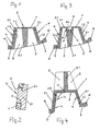
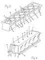
- the sheet metal shell 1 has wall sections 1.1, 1.2 and 1.3, the angled to each other stand. Since it is in the sheet metal shell 1 to a in Drawing process manufactured sheet metal parts are the Angle on the one hand between the wall part 1.1 and the Wall 1.2 and the other between the wall part 1.1 and the wall part 1.3 slightly larger than 90 degrees and are in the order of 110 to 130 Degree. Between the wall parts 1.2 and 1.3 extend reinforcing ribs 2, which also on the wall part 1.1 of the sheet metal shell 1 are connected.
- the Reinforcing ribs 2 consist of a molded Plastic material 2.1, which further reinforcing ribs forms, which are transverse to the reinforcing ribs. 2 run and with these at intersections in one piece can be connected.
- the reinforcing ribs 2 forming plastic material 2.1 can at least in the Neighboring the reinforcing ribs 2 continue one Coating on the relevant side of the sheet metal shell 1 form.
- connection point 3 or 4 is assigned. Perpendicular There is such a positive connection to this level not at the same connection point 3, 4, for this positive connection in to the level of the respective connection point 3,4 vertical direction provide those
- Interfaces 4 or 3 in the second level preferably at an angle greater than 90 degrees at an angle of 110 to 130 degrees to the first Level.
- connection points 3 and 4 if there respectively Breakthroughs 5 are available.
- connection points 3, 4 also bumps 7 may be provided in the Sheet metal shell 1 are formed.
- Such Connection point shows Figure 3, here is the hump. 7 in the area of the wall 1.1.
- the sheet metal shell 1 means of the plastic material 2.1, which is the Forms stiffening webs 2, molded.
- the lying in the plastic flow direction Contact surface 7.1 of the hump 7 is here also cylindrical or against the plastic flow direction Conically rejuvenated trained in order to Direction in which projects the hump 7, a positive Connection between the hump 7 and the Plastic material 2.1 can not be achieved.
- connection points 3, 4 can instead of a Breakthrough 5 or a hump 7 also cup-like depressions, namely be provided wells 8, such Cup 8 is also in Figure 3 through the interior of the hump there 7 formed, although this cup 8 does not function here as connection point 3 or 4.
- a such cup 8 by filling with the plastic material 2.1 serve in the same way as a connection point can.
- the inner wall is 8.1 of the cup 8 either hollow cylindrical or it opens opposite the plastic flow direction conical to on this Also make a positive connection between the plastic material 2.1 and the cup wall 8.1 perpendicular to the plane of the associated connection point 3 or 4 to avoid.
- FIGS. 1 and 3 show a sheet metal shell 1, in which stiffening webs 2 and thus the Plastic material 2.1 on the inner hollow side of Sheet metal shell 1 are arranged
- Figure 4 shows an embodiment, at the stiffening webs 2 and the plastic material 2.1 on the outer, raised side of the arranged three-dimensionally shaped sheet metal shell 1 are.
- the connection points are 3 and 4 here in the same way as in the embodiments executed according to Figures 1 and 3, only is here the runner side reversed and accordingly the flow direction the plastic material 2.1 during the injection molding process reversed relative to the sheet metal shell 1.
- connection points 3 and 4 in particular meets very high standards in terms of strength and rigidity of the sheet metal shell 1 and the reinforcing ribs 2 and optionally from the plastic material 2.1 formed coating when the plastic material 2.1 clasps the longitudinal edges of the sheet metal shell 1.
- the sheet metal shells 1 angled along their edges outwards Flanges 9 on which of the plastic material 2.1 are encompassed, creating an extensive sheathing 10 of the flanges 9 is formed.
- connection points 3, 4 are at the location of the connection points 3, 4 on the sheet metal shell 1 by no means ge those places tied, where the reinforcing ribs 2 on the wall parts 1.1, 1.2 or 1.3. Also need the connection points 3, 4 do not lie where a crossing point of the reinforcing ribs 2 at the respective Wall part 1.1 to 1.3 of the sheet metal shells is located.
- the reinforcing ribs 2 in one piece with a coating of the relevant walls 1.1. to 1.3 be the sheet metal shell 1, in the area of the Connection points 3. 4 are located, which are thus at a distance from a crossing point of the reinforcing ribs 2 or from the crossing points of the reinforcing ribs 2 in this coating lie.
- FIGs 7 and 8 illustrate embodiments at where the connection points are arranged in planes, which include only small angles with each other.
- connection points 3 and 4 To the desired positive locking at the connection points 3 and 4 is the plastic material at the sheet metal station 1 opposite each other Connecting points integrally connected. This is preferably done by one of the reinforcing ribs Second
Landscapes
- Engineering & Computer Science (AREA)
- Architecture (AREA)
- Structural Engineering (AREA)
- Chemical & Material Sciences (AREA)
- Combustion & Propulsion (AREA)
- Transportation (AREA)
- Mechanical Engineering (AREA)
- Injection Moulding Of Plastics Or The Like (AREA)
- Laminated Bodies (AREA)
- Body Structure For Vehicles (AREA)
Applications Claiming Priority (2)
| Application Number | Priority Date | Filing Date | Title |
|---|---|---|---|
| DE20310656U | 2003-07-11 | ||
| DE20310656U DE20310656U1 (de) | 2003-07-11 | 2003-07-11 | Hybridbauteil für Kraftfahrzeuge |
Publications (2)
| Publication Number | Publication Date |
|---|---|
| EP1495947A2 true EP1495947A2 (fr) | 2005-01-12 |
| EP1495947A3 EP1495947A3 (fr) | 2008-08-20 |
Family
ID=28051624
Family Applications (1)
| Application Number | Title | Priority Date | Filing Date |
|---|---|---|---|
| EP04013581A Withdrawn EP1495947A3 (fr) | 2003-07-11 | 2004-06-09 | Pièce de structure composite pour véhicule |
Country Status (2)
| Country | Link |
|---|---|
| EP (1) | EP1495947A3 (fr) |
| DE (1) | DE20310656U1 (fr) |
Cited By (3)
| Publication number | Priority date | Publication date | Assignee | Title |
|---|---|---|---|---|
| US10583629B2 (en) * | 2015-02-06 | 2020-03-10 | Kobe Steel, Ltd. | Joining structure |
| US20220242091A1 (en) * | 2008-11-07 | 2022-08-04 | Zephyros, Inc. | Hybrid Reinforcement Structure |
| EP4117884A1 (fr) * | 2020-03-12 | 2023-01-18 | Kautex Textron GmbH & Co. Kg | Pièce fonctionnalisée et étanche |
Families Citing this family (5)
| Publication number | Priority date | Publication date | Assignee | Title |
|---|---|---|---|---|
| FR2866306B1 (fr) | 2004-02-17 | 2006-05-26 | Valeo Thermique Moteur Sa | Structure composite en metal et matiere plastique, en particulier pour une face avant de vehicule automobile. |
| DE102007028076A1 (de) | 2007-06-15 | 2008-12-18 | Innovent E.V. | Verfahren zur Herstellung stabiler und mediendichter Metall-Kunststoff-Spritzgussverbunde |
| DE102008010834A1 (de) * | 2008-02-23 | 2009-08-27 | Daimler Ag | Rahmenbauteil und ein Verfahren zu dessen Herstellung |
| DE102011012521A1 (de) * | 2011-02-26 | 2012-08-30 | Gm Global Technology Operations, Inc. | Fahrzeugkarosseriestruktur eines Kraftfahrzeuges |
| DE102024003642A1 (de) | 2024-11-07 | 2026-05-07 | Mercedes-Benz Group AG | Karosseriebauteil und Herstellungsverfahren |
Family Cites Families (6)
| Publication number | Priority date | Publication date | Assignee | Title |
|---|---|---|---|---|
| JPH10264855A (ja) * | 1997-03-26 | 1998-10-06 | Aisin Seiki Co Ltd | 車両フロントエンドモジュール構造 |
| DE19848516A1 (de) * | 1998-10-21 | 2000-04-27 | Bayer Ag | Hohlkammer-Leichtbauteil |
| EP1163094B1 (fr) * | 1999-03-23 | 2004-02-11 | Rhodia Engineering Plastics SA | Articles mixtes comprenant une partie rigide et une partie a base d'un materiau thermoplastique, et procede de fabrication |
| FR2798355B1 (fr) * | 1999-09-15 | 2001-12-14 | Valeo Thermique Moteur Sa | Element de structure composite, notamment support de face avant pour vehicule |
| DE10014332C2 (de) * | 2000-03-24 | 2002-03-14 | Basf Ag | Verbundbauteil und Verfahren zur seiner Herstellung |
| EP1213207B2 (fr) * | 2000-12-07 | 2014-11-26 | Calsonic Kansei Corporation | Structure de support pour bloc de radiateur d'un véhicule |
-
2003
- 2003-07-11 DE DE20310656U patent/DE20310656U1/de not_active Expired - Lifetime
-
2004
- 2004-06-09 EP EP04013581A patent/EP1495947A3/fr not_active Withdrawn
Cited By (6)
| Publication number | Priority date | Publication date | Assignee | Title |
|---|---|---|---|---|
| US20220242091A1 (en) * | 2008-11-07 | 2022-08-04 | Zephyros, Inc. | Hybrid Reinforcement Structure |
| US12240215B2 (en) * | 2008-11-07 | 2025-03-04 | Zephyros, Inc. | Hybrid reinforcement structure |
| US10583629B2 (en) * | 2015-02-06 | 2020-03-10 | Kobe Steel, Ltd. | Joining structure |
| EP4117884A1 (fr) * | 2020-03-12 | 2023-01-18 | Kautex Textron GmbH & Co. Kg | Pièce fonctionnalisée et étanche |
| EP4117884B1 (fr) * | 2020-03-12 | 2025-08-06 | Kautex Textron GmbH & Co. Kg | Pièce fonctionnalisée et étanche |
| US12409898B2 (en) | 2020-03-12 | 2025-09-09 | Kautex Textron Gmbh & Co. Kg | Functionalised and sealed part |
Also Published As
| Publication number | Publication date |
|---|---|
| EP1495947A3 (fr) | 2008-08-20 |
| DE20310656U1 (de) | 2003-09-11 |
Similar Documents
| Publication | Publication Date | Title |
|---|---|---|
| DE69721180T2 (de) | Kunststoffplatte für Kraftfahrzeuge | |
| DE60317029T2 (de) | Schalenförmiger Stossfängerträger mit Lagerung für ein senkrecht zu den Längsholmen verlaufendes Verstärkungselement | |
| EP1916361B1 (fr) | Poignée prevue pour être montée dans une ouverture | |
| DE102005055705C5 (de) | Montageträger in Hybridstruktur | |
| DE102012108858A1 (de) | Flüssigkeitstank mit einem Verbindungselement | |
| EP1504983B1 (fr) | Châssis auxiliaire pour véhicules | |
| WO2008135053A1 (fr) | Réservoir en matière plastique | |
| DE3020997C2 (de) | Stoßfänger für Kraftfahrzeuge | |
| DE4424191B4 (de) | Abdeckung, insbesondere Modul- oder Bausteinabdeckung, für eine Luft- oder Gassackeinrichtung | |
| EP2138332B1 (fr) | Système d'attelage de remorque | |
| EP1495947A2 (fr) | Pièce de structure composite pour véhicule | |
| DE102005017956B4 (de) | Stoßenergieaufnahmevorrichtung | |
| DE2526914A1 (de) | Stossdaempfer fuer kraftfahrzeuge | |
| WO2021255042A1 (fr) | Ensemble support de chambre creuse pour véhicule | |
| DE19958299B4 (de) | Deformationselement | |
| DE102012108851A1 (de) | Flüssigkeitstank mit einer Schwallwand | |
| EP1730016B1 (fr) | Support transversal ou composant structurel pour vehicule automobile | |
| EP0897361B1 (fr) | Chassis | |
| DE19855360B4 (de) | Klappe für einen Luftführungskanal | |
| EP2335982B1 (fr) | Elément d'absorbeur pour un véhicule automobile | |
| EP1690753A2 (fr) | Composant pour le montage d'un élément de carrosserie de véhicule | |
| DE69001660T2 (de) | Kraftfahrzeugstossfaenger mit energieabsorbierenden mitteln. | |
| DE102009010345A1 (de) | Frontendmodul für Fahrzeuge | |
| DE3407985C2 (fr) | ||
| DE69500224T2 (de) | Verbindungsvorrichtung für die benachbarten enden zweier hohlträgerstücke |
Legal Events
| Date | Code | Title | Description |
|---|---|---|---|
| PUAI | Public reference made under article 153(3) epc to a published international application that has entered the european phase |
Free format text: ORIGINAL CODE: 0009012 |
|
| AK | Designated contracting states |
Kind code of ref document: A2 Designated state(s): AT BE BG CH CY CZ DE DK EE ES FI FR GB GR HU IE IT LI LU MC NL PL PT RO SE SI SK TR |
|
| AX | Request for extension of the european patent |
Extension state: AL HR LT LV MK |
|
| PUAL | Search report despatched |
Free format text: ORIGINAL CODE: 0009013 |
|
| AK | Designated contracting states |
Kind code of ref document: A3 Designated state(s): AT BE BG CH CY CZ DE DK EE ES FI FR GB GR HU IE IT LI LU MC NL PL PT RO SE SI SK TR |
|
| AX | Request for extension of the european patent |
Extension state: AL HR LT LV MK |
|
| AKX | Designation fees paid | ||
| STAA | Information on the status of an ep patent application or granted ep patent |
Free format text: STATUS: THE APPLICATION IS DEEMED TO BE WITHDRAWN |
|
| 18D | Application deemed to be withdrawn |
Effective date: 20090221 |
|
| REG | Reference to a national code |
Ref country code: DE Ref legal event code: 8566 |