EP1495955B1 - Véhicule avec pile à combustible - Google Patents
Véhicule avec pile à combustible Download PDFInfo
- Publication number
- EP1495955B1 EP1495955B1 EP04014955A EP04014955A EP1495955B1 EP 1495955 B1 EP1495955 B1 EP 1495955B1 EP 04014955 A EP04014955 A EP 04014955A EP 04014955 A EP04014955 A EP 04014955A EP 1495955 B1 EP1495955 B1 EP 1495955B1
- Authority
- EP
- European Patent Office
- Prior art keywords
- fuel cell
- fuel
- vehicle
- cylinder
- cell stack
- Prior art date
- Legal status (The legal status is an assumption and is not a legal conclusion. Google has not performed a legal analysis and makes no representation as to the accuracy of the status listed.)
- Expired - Lifetime
Links
Images





Classifications
-
- B—PERFORMING OPERATIONS; TRANSPORTING
- B60—VEHICLES IN GENERAL
- B60L—PROPULSION OF ELECTRICALLY-PROPELLED VEHICLES; SUPPLYING ELECTRIC POWER FOR AUXILIARY EQUIPMENT OF ELECTRICALLY-PROPELLED VEHICLES; ELECTRODYNAMIC BRAKE SYSTEMS FOR VEHICLES IN GENERAL; MAGNETIC SUSPENSION OR LEVITATION FOR VEHICLES; MONITORING OPERATING VARIABLES OF ELECTRICALLY-PROPELLED VEHICLES; ELECTRIC SAFETY DEVICES FOR ELECTRICALLY-PROPELLED VEHICLES
- B60L58/00—Methods or circuit arrangements for monitoring or controlling batteries or fuel cells, specially adapted for electric vehicles
- B60L58/30—Methods or circuit arrangements for monitoring or controlling batteries or fuel cells, specially adapted for electric vehicles for monitoring or controlling fuel cells
- B60L58/32—Methods or circuit arrangements for monitoring or controlling batteries or fuel cells, specially adapted for electric vehicles for monitoring or controlling fuel cells for controlling the temperature of fuel cells, e.g. by controlling the electric load
- B60L58/33—Methods or circuit arrangements for monitoring or controlling batteries or fuel cells, specially adapted for electric vehicles for monitoring or controlling fuel cells for controlling the temperature of fuel cells, e.g. by controlling the electric load by cooling
-
- B—PERFORMING OPERATIONS; TRANSPORTING
- B60—VEHICLES IN GENERAL
- B60L—PROPULSION OF ELECTRICALLY-PROPELLED VEHICLES; SUPPLYING ELECTRIC POWER FOR AUXILIARY EQUIPMENT OF ELECTRICALLY-PROPELLED VEHICLES; ELECTRODYNAMIC BRAKE SYSTEMS FOR VEHICLES IN GENERAL; MAGNETIC SUSPENSION OR LEVITATION FOR VEHICLES; MONITORING OPERATING VARIABLES OF ELECTRICALLY-PROPELLED VEHICLES; ELECTRIC SAFETY DEVICES FOR ELECTRICALLY-PROPELLED VEHICLES
- B60L58/00—Methods or circuit arrangements for monitoring or controlling batteries or fuel cells, specially adapted for electric vehicles
- B60L58/30—Methods or circuit arrangements for monitoring or controlling batteries or fuel cells, specially adapted for electric vehicles for monitoring or controlling fuel cells
-
- B—PERFORMING OPERATIONS; TRANSPORTING
- B62—LAND VEHICLES FOR TRAVELLING OTHERWISE THAN ON RAILS
- B62K—CYCLES; CYCLE FRAMES; CYCLE STEERING DEVICES; RIDER-OPERATED TERMINAL CONTROLS SPECIALLY ADAPTED FOR CYCLES; CYCLE AXLE SUSPENSIONS; CYCLE SIDECARS, FORECARS, OR THE LIKE
- B62K2202/00—Motorised scooters
-
- B—PERFORMING OPERATIONS; TRANSPORTING
- B62—LAND VEHICLES FOR TRAVELLING OTHERWISE THAN ON RAILS
- B62K—CYCLES; CYCLE FRAMES; CYCLE STEERING DEVICES; RIDER-OPERATED TERMINAL CONTROLS SPECIALLY ADAPTED FOR CYCLES; CYCLE AXLE SUSPENSIONS; CYCLE SIDECARS, FORECARS, OR THE LIKE
- B62K2204/00—Adaptations for driving cycles by electric motor
-
- Y—GENERAL TAGGING OF NEW TECHNOLOGICAL DEVELOPMENTS; GENERAL TAGGING OF CROSS-SECTIONAL TECHNOLOGIES SPANNING OVER SEVERAL SECTIONS OF THE IPC; TECHNICAL SUBJECTS COVERED BY FORMER USPC CROSS-REFERENCE ART COLLECTIONS [XRACs] AND DIGESTS
- Y02—TECHNOLOGIES OR APPLICATIONS FOR MITIGATION OR ADAPTATION AGAINST CLIMATE CHANGE
- Y02T—CLIMATE CHANGE MITIGATION TECHNOLOGIES RELATED TO TRANSPORTATION
- Y02T90/00—Enabling technologies or technologies with a potential or indirect contribution to GHG emissions mitigation
- Y02T90/40—Application of hydrogen technology to transportation, e.g. using fuel cells
-
- Y—GENERAL TAGGING OF NEW TECHNOLOGICAL DEVELOPMENTS; GENERAL TAGGING OF CROSS-SECTIONAL TECHNOLOGIES SPANNING OVER SEVERAL SECTIONS OF THE IPC; TECHNICAL SUBJECTS COVERED BY FORMER USPC CROSS-REFERENCE ART COLLECTIONS [XRACs] AND DIGESTS
- Y10—TECHNICAL SUBJECTS COVERED BY FORMER USPC
- Y10S—TECHNICAL SUBJECTS COVERED BY FORMER USPC CROSS-REFERENCE ART COLLECTIONS [XRACs] AND DIGESTS
- Y10S903/00—Hybrid electric vehicles, HEVS
- Y10S903/902—Prime movers comprising electrical and internal combustion motors
- Y10S903/903—Prime movers comprising electrical and internal combustion motors having energy storing means, e.g. battery, capacitor
-
- Y—GENERAL TAGGING OF NEW TECHNOLOGICAL DEVELOPMENTS; GENERAL TAGGING OF CROSS-SECTIONAL TECHNOLOGIES SPANNING OVER SEVERAL SECTIONS OF THE IPC; TECHNICAL SUBJECTS COVERED BY FORMER USPC CROSS-REFERENCE ART COLLECTIONS [XRACs] AND DIGESTS
- Y10—TECHNICAL SUBJECTS COVERED BY FORMER USPC
- Y10S—TECHNICAL SUBJECTS COVERED BY FORMER USPC CROSS-REFERENCE ART COLLECTIONS [XRACs] AND DIGESTS
- Y10S903/00—Hybrid electric vehicles, HEVS
- Y10S903/902—Prime movers comprising electrical and internal combustion motors
- Y10S903/903—Prime movers comprising electrical and internal combustion motors having energy storing means, e.g. battery, capacitor
- Y10S903/904—Component specially adapted for hev
- Y10S903/908—Fuel cell
Definitions
- the present invention relates to a fuel cell vehicle driven with a fuel cell as a drive energy source, and particularly to a fuel cell vehicle in which drivability is improved by arranging heavy components at an appropriate position.
- a fuel cell type two-wheeled vehicle that is driven by supplying electrical power generated by a fuel cell to a motor and driving a rear wheel using this motor is known.
- electricity is generated by a chemical reaction between hydrogen, as a fuel gas, and oxygen, as a reactant gas, but methods of supplying hydrogen are roughly divided into two types for a vehicle fuel cell.
- On is a method of installing methanol as fuel, extracting hydrogen from the methanol using a reformer, and the other is a method of filling hydrogen gas into the fuel cylinder in advance.
- methanol as fuel
- extracting hydrogen from the methanol using a reformer is a method of filling hydrogen gas into the fuel cylinder in advance.
- a fuel cylinder filled with fuel gas and a fuel cell stack (or cell stack) for converting the fuel gas to electrical energy constitute the main structure. Because the fuel cylinder and the fuel cell stack are heavy, the barycentric position is made higher due to the arrangement position of these components.
- Japanese patent 2001-130469 and Japanese patent 2001-313056 disclose technology where a fuel cell stack is arranged above a step floor below a seat, and a fuel cylinder is mounted above a rear wheel to the rear of the seat.
- the preamble of claim 1 is based on US-B1-6326765 .
- the fuel cell 112 is located above a lower part of the frame 132.
- the fuel cell 33 is located above a lower frame 12.
- the fuel cell 10 is located below the vehicle floor plane.
- the cell stack body 7 is disposed in a space formed on the front frame 22, the rear frame 23 and the center frame 24 as viewed from the side of the vehicle, i.e. the frame surrounds the fuel cell on front, top and rear sides, but not laterally.
- the object of the present invention is to solve the above-described technical problems in the related art, and to provide a fuel cell two-wheeled vehicle in which a fuel cylinder and a fuel cell stack are arranged so that the barycentric position is kept low and load is appropriately shared between the front and rear wheels.
- the present invention is directed to a fuel cell vehicle in accordance with claim 1.
- the fuel cell vehicle is provided with a fuel cylinder and a fuel cell stack, and driven by electrical power obtained by causing an electrochemical reaction between fuel gas and reactant gas.
- the heavy fuel cylinder and fuel cell stack are arranged concentrated at a single place, drivability is improved by centralizing mass. Also, since the fuel cylinder and the fuel cell stack are arranged further forward than the seating position, it is possible to arrange the fuel cylinder and the fuel cell stack close to each other, with the result that it is possible to shorten the length of a fuel gas supply passage.
- Fig. 1 is a partially fractured cross sectional drawing showing the main structure of a fuel cell motorcycle of the present invention
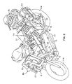
- Fig. 2 is a perspective view of the motorcycle
- Fig. 3 is a schematic drawing of a vehicle frame skeleton.
- the vehicle frame 10 is made up of a head pipe 11, a pair of left and right upper down frames 13 (L, R) extending diagonally downwards with the head pipe 11 as a start point, a pair of left and right lower down frames 12 (L, R) further down that he upper down frames 13 extending downwards with the head pipe 11 as a start point, a pair of left and right upper frames 14 (L, R) extending diagonally upwards from substantially the center of the lower down frames 12 and connecting to the other end of the upper down frames 13 midway, and a pair of left and right lower frames 15 (L, R) further down than the upper frames 14 and extending to the rear from a lower end of the lower down frames 12.
- the vehicle frame 10 is also a substantially square annular structure, provided with an annular frame 16 supporting a rear end of the upper frame 14 and the lower frame 15 at the four corners of the square annular structure, a rear plate 17 extending diagonally upwards from the rear end of the lower frame 15, and an upper connecting frame 18 and a lower connecting frame 19 connected at a position where the lower frame 14 and the lower frame 15 connect.
- a front fork 32 axially supporting a front wheel FW and steering handle 30 connected to the front fork 32 are supported on the head pipe 11 a manner capable of being steered.
- a pair of left and right swing frames 20 are swingably supported at a lower part of the rear plate 17 with a shaft 21 as a fulcrum, and a rear wheel WR as a drive wheel is supported at a rear end of the swing frames 20.
- the motorcycle of the present invention includes a fuel cell box 42 storing a fuel cell stack (48), a fuel cylinder 41 storing fuel gas (hydrogen) for supply to the fuel cell stack inside the fuel cell box 42, and a piping system 43 for supplying scavenge gas taken in from the atmosphere and reactant gas and cooling gas to the inside of the fuel cell box 42, and also has a plurality of secondary batteries 81, 93 and fuel cells 82 fitted as an auxiliary power source.
- a fuel cell box 42 storing a fuel cell stack (48), a fuel cylinder 41 storing fuel gas (hydrogen) for supply to the fuel cell stack inside the fuel cell box 42, and a piping system 43 for supplying scavenge gas taken in from the atmosphere and reactant gas and cooling gas to the inside of the fuel cell box 42, and also has a plurality of secondary batteries 81, 93 and fuel cells 82 fitted as an auxiliary power source.
- the fuel cylinder 41 is supported by and between the left and right upper frames 14, and is mounted further forward than a seat 31 along the upper frames 14, at an inclined attitude such that the shut-off valve 44 side faces to the rear and one end of the shut-off valve side is higher than the other end.
- Fig. 4 is a front view showing the appearance of the fuel cylinder 41 supported by the upper frames 14, and since the left and right upper frames 14 (L, R) have a narrower gap between the two going from bottom to top, it is possible to support the fuel cylinder 41 in a recumbent attitude.
- An impact-absorbing member is fitted to a surface of the upper frames 14 contacting the fuel cylinder 41.
- the fuel cylinder 41 is rigidly restrained in the upper frames 14 by a suitable restraint, such as binding bands 24, 25.
- the fuel cell box 42 is positioned below the fuel cylinder 41 between the pair of left and right lower frames 15, and is fixed by being suspended from brackets 38, 39 provided at two places (a total of four places) on the left and right upper frames 14 (L, R), so as to overlap and run along a line connecting a rotational axis of the front wheel FW and the rotational axis of the rear wheel RW.
- the fuel cylinder 41 and the fuel cell box 42 are arranged so that the fuel cylinder 41 is positioned almost directly above the fuel cell stack, and the seat is positioned behind them, which means that drivability is improved by centralizing the mass. Also, since the fuel cylinder 41 and the fuel cell box 42 are arranged further forward than the seat position, load shared by the rear wheel which was excessive previously, is reduced, while load shared by the front wheel, which was slight previously, is increased, which means that load sharing between the front and ear wheels is made suitable. Also, since the fuel cylinder 41 and the fuel cell stack are arranged close to each other it is possible to shorten the length of a fuel gas supply passage.
- Secondary batteries 81, 83, as an auxiliary power source, and the fuel cell 82 are arranged in a dispersed manner at the front of the vehicle, below the seat 31 and at the rear of the vehicle, respectively.
- a down converter 84 for converting the output voltage of the fuel cell system to a voltage for auxiliary devices (for example, 12V), and peripheral circuits for the down converter, are mounted to the rear of the vehicle.
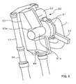
- Fig. 5 is a drawing of the blower module 60 looking diagonally from the front right of the vehicle
- Fig. 6 is a drawing of the blower module 60 looking diagonally from the front left of the vehicle
- reference numbers that are the same in the two drawings represent the same parts.
- the blower module 60 is mainly comprised of a blower body 61 housing a blower motor and a blower fan (neither of which are shown in the drawing), an air cleaner 63, and an intake pipe 62 connecting the air cleaner 63 and the blower body 61.
- the air cleaner 63 has an air filter 63c housed inside a case made up of a right case 63a and a left case 63b.
- An intake port 64 for taking in external air is formed in a lower end side of the right case 63a, while an exhaust port 65 is formed in a main surface of the left case 63b.
- the intake pipe 62 is connected to the exhaust port 65.
- the air cleaner 63 is attached to the vehicle body at an attitude with the intake port 64 oriented diagonally downwards to the left of the vehicle body.
- a cut-out 63d is formed in the side surface of the air cleaner 63, and a blower motor section 61a of the blower body 61 is stored in the cut-out 63d.
- the intake pipe 62 is put at negative pressure, and external air is sucked from the intake port 64 of the air cleaner 63.
- This external air is filtered by the air filter 63c inside the air cleaner 63, then taken in to the inside of the intake pipe 62 from the exhaust port 65 and finally supplied to a blowing passage 71 by means of the blower body 61.
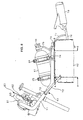
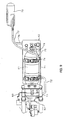
- Fig. 8 and Fig. 9 are a side elevation ( Fig. 8 ) and a front elevation ( Fig. 9 ) showing the structure of a piping system 43 connected to a subsequent stage to the blower module 60, and reference numerals that are the same in these two drawing represent the same parts.
- Two bypass valves 73, 74 are provided in the 71, and a scavenge gas supply passage 72 for introducing external air into the inside of the fuel cell box 42 as scavenge gas is branched from the upstream bypass valve 73.
- the upstream bypass valve 73 is an electromagnetic valve, and external air is only supplied to the scavenge gas supply passage 72 when this valve is open.
- the downstream bypass valve 74 contains an electromagnetic three-way valve, and the blowing passage 71 branches into a reactant gas supply passage 75 and a cooling gas supply passage 79 at the downstream bypass valve 74.
- Each of the upstream and downstream bypass valves 73, 74 are subjected to opening and closing control by the same ECU that controls the vehicle.
- the reactant gas supply passage 75 supplies external that is supplied from the blowing passage 71 to the fuel cell stack 48 as reactant gas (oxygen).
- the cooling gas supply passage 79 supplies external air supplied from the blowing passage 71 to the fuel cell stack 48 as cooling gas.
- the reactant gas supply passage 75 and the cooling gas supply passage 79 are divided to the left side (cooling gas supply passage 79) and the right side (reactant gas supply passage 75) of the vehicle body, so that internal gas (air) is cooled by being blown by traveling wind.
- the blower module 60 is energized to commence suction of external air, and pumping of the sucked in air, which means that the external air passes from the upstream bypass valve 73 of the blowing passage 71 through the scavenge gas supply passage 72, and is guided to the inside of the fuel cell box 42 as scavenge air.
- the downstream bypass valve 74 is open with this embodiment, the external air is supplied through the reactant gas supply passage 75 to the fuel cell stack 48, and also supplied through the cooling gas supply passage 79 to the fuel cell stack 48.
- the temperature Tbatt of the fuel cell stack 48 is routinely measured by a temperature sensor, not shown, and if the ignition switch is turned off, the stack temperature Tbatt is compared with a specified reference temperature Tref1. Control is carried out so that if Tbatt ⁇ Tref 1, the downstream bypass valve 74 does not supply eternal air that has been supplied from the blowing passage 71 to either the reactant gas supply passage 75 side or to the cooling gas supply passage 79, while if Tbatt ⁇ Tref 2 supply to the reactant gas supply passage 75 side is stopped and supply only continues to the cooling gas supply passage 79.
- a scavenge air outlet passage 76 for discharging the scavenge gas, and a hydrogen outlet passage 77 for discharging purged fuel gas (hydrogen) are also connected to the fuel cell box 42, and the other end of each passage is connected to a silencer 70.
- the scavenge gas and purged hydrogen gas are mixed in the silencer 70 and discharged to the outside. In this way, with this embodiment scavenge gas and purged hydrogen gas are discharged through the silencer 70, which means that it is possible to reduce exhaust noise.
- the fuel cylinder 41 and the fuel cell box 42 are connected by a fuel gas supply passage 78, and fuel gas (hydrogen) to the fuel cell stack 48 inside the fuel cell box 42 is supplied from the fuel cylinder 41 through this fuel gas supply passage 78.
- fuel gas hydrogen
- the voltage of each cell constituting the fuel cell stack is monitored, and if even one of them drops below a reference voltage hydrogen purging is carried out.
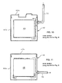
- Fig. 10 and Fig. 11 are a cross section along line A - A and line B - B of the fuel cell box 42 ( Fig. 8 ), and the same reference numerals in each drawing represent the same parts.
- the substantially cube-shaped fuel cell stack 48 is supported so that a scavenge air space is ensured between the 6 surfaces of the fuel cell stack 48 and the box cases 42a, 42b.
- External air introduced from the scavenge gas supply passage 72 to the inside of the fuel cell box 42 as scavenge gas turns gas retained in the space between the box cases 42a and 42b and the fuel cell stack 48 into scavenge gas and discharges it from the scavenge air outlet passage 76.
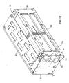
- Fig. 12 is a perspective view of the fuel cell stack 48, and a laminated body 90, which is a main part of the fuel cell stack 48 is constructed of a plurality of cells 50 laminated in the direction of arrow A, and with power collection electrodes 58 arranged on either side.
- Fig. 13 is a plan view of a cell
- Fig. 14 is a cross section along line A - A in Fig.
- a cell 50 is constructed by overlapping a negative electrode side separator 51, a negative electrode 52, a fuel cell ion exchange membrane 53, a positive electrode 54 and a positive electrode side separator 55, and as shown in Fig. 13 , has a cooling gas manifold 56 and a reactant gas manifold 57 formed for passing these components through.
- the negative electrode 52 and the positive electrode 54 are formed from a catalyst bed and a porous layer, and have a gas diffusion function.
- a cooling gas flow groove 51a is formed in the negative electrode side separator 51, in an outer main surface, and a hydrogen flow groove 51b is formed in a surface of the negative electrode side separator 51 that is opposite the fuel cell ion exchange membrane 53, at an inner main surface.
- An air flow passage 55b is formed in a surface of the negative electrode 52 that is opposite to the fuel cell ion exchange membrane 53.
- the cooling gas flow groove 51a links to the cooling gas manifold 56, and the air flow passage 55b links to the reactant gas manifold 57.
- the laminated body 90 is covered by endplates 93 arranged on both sides in a laminate direction, side plates 94 arranged on the sides, a top plate 95 arranged at the top, and a bottom plate arranged at the bottom, and pressure increase is maintained so that a constant elastic force acts in the laminate direction.
- a reactant gas introduction port 91 and a cooling gas introduction port 92 are provided in endplate 93 side end sections.
- the reactant gas introduction port 91 links to the reactant gas manifold 57 , and external air from the reactant gas supply passage 75 is introduced as reactant gas for power generation. This reactant gas is supplied to the air flow passage 55b through the reactant gas manifold 57.
- the cooling gas introduction port 92 is linked to the cooling gas manifold 56, and cooling gas is introduced from an end section of the blowing passage 71. This cooling as is supplied through the cooling gas manifold 56 to the cooling gas flow groove 51a.
- the invention provides a fuel cell vehicle in which a fuel cylinder and a fuel cell stack are arranged so that the barycentric position is kept low and load is appropriately shared between the front and rear wheels.
- the fuel cylinder 41 is mounted further forward than a seat 31, at an recumbent attitude inclined such that the shut-off valve 44 side faces to the rear and the shut-off valve end is higher than the other end.
- the fuel cell box 42 is positioned below the fuel cylinder 41 between the pair of left and right lower frames 15, and is fixed by being suspended from brackets 38, 39 provided at two places on the left and right upper frames 14 (L, R), so as to overlap and run along a line connecting a rotational axis of the front wheel FW and the rotational axis of the rear wheel RW.
Landscapes
- Engineering & Computer Science (AREA)
- Life Sciences & Earth Sciences (AREA)
- Sustainable Development (AREA)
- Sustainable Energy (AREA)
- Power Engineering (AREA)
- Transportation (AREA)
- Mechanical Engineering (AREA)
- Fuel Cell (AREA)
- Arrangement Or Mounting Of Propulsion Units For Vehicles (AREA)
- Automatic Cycles, And Cycles In General (AREA)
Claims (4)
- Véhicule à pile à combustible, pourvu d'un récipient à combustible (41) et d'un empilement de piles à combustible (48) stocké dans un boîtier de pile à combustible (42), et se déplaçant à l'aide d'une énergie électrique obtenue par l'intermédiaire de l'alimentation d'un empilement de piles à combustible (48) en gaz combustible et en gaz réactif, comprenant un châssis de véhicule (10) pour supporter le récipient à combustible (41) et le boîtier de pile à combustible (42) de sorte que le récipient à combustible (41) soit positionné presque directement au-dessus du boîtier de pile à combustible (42), et une section de siège (31) prévue plus à l'arrière du véhicule que la position où le récipient à combustible (41) et le boîtier de pile à combustible (42) sont supportés,
caractérisé en ce que le boîtier de pile à combustible (42) est agencé dans la position la plus basse du châssis de véhicule (10), le long et entre une paire de châssis inférieurs gauche et droit (15R, 15L) prévus pour s'étendre dans une direction longitudinale du véhicule. - Véhicule à pile à combustible selon la revendication 1, dans lequel le boîtier de pile à combustible (42) est agencé le long d'une ligne droite reliant un axe de rotation d'une roue avant (FW) et un axe de rotation d'une roue arrière (RW) et chevauchant cette ligne.
- Véhicule à pile à combustible selon la revendication 1 ou 2, dans lequel le récipient à combustible (41) est supporté dans une direction longitudinale du véhicule et dans une orientation inclinée selon un angle spécifié.
- Véhicule à pile à combustible selon la revendication 3, dans lequel le récipient à combustible (41) est supporté dans une orientation inclinée avec une extrémité à soupape d'arrêt (44) du récipient à combustible (41) à l'arrière, cette extrémité arrière étant plus élevée que l'autre extrémité.
Applications Claiming Priority (2)
| Application Number | Priority Date | Filing Date | Title |
|---|---|---|---|
| JP2003195926 | 2003-07-11 | ||
| JP2003195926A JP4093929B2 (ja) | 2003-07-11 | 2003-07-11 | 燃料電池車両 |
Publications (3)
| Publication Number | Publication Date |
|---|---|
| EP1495955A2 EP1495955A2 (fr) | 2005-01-12 |
| EP1495955A3 EP1495955A3 (fr) | 2009-02-18 |
| EP1495955B1 true EP1495955B1 (fr) | 2010-05-19 |
Family
ID=33448029
Family Applications (1)
| Application Number | Title | Priority Date | Filing Date |
|---|---|---|---|
| EP04014955A Expired - Lifetime EP1495955B1 (fr) | 2003-07-11 | 2004-06-25 | Véhicule avec pile à combustible |
Country Status (8)
| Country | Link |
|---|---|
| US (1) | US7121366B2 (fr) |
| EP (1) | EP1495955B1 (fr) |
| JP (1) | JP4093929B2 (fr) |
| CN (1) | CN100333934C (fr) |
| CA (1) | CA2473261C (fr) |
| DE (1) | DE602004027194D1 (fr) |
| ES (1) | ES2343954T3 (fr) |
| TW (1) | TWI265891B (fr) |
Families Citing this family (22)
| Publication number | Priority date | Publication date | Assignee | Title |
|---|---|---|---|---|
| JP4079430B2 (ja) * | 2003-07-11 | 2008-04-23 | 本田技研工業株式会社 | 燃料電池車両 |
| JP4081430B2 (ja) * | 2003-11-19 | 2008-04-23 | 本田技研工業株式会社 | 燃料電池車両 |
| JP4498856B2 (ja) * | 2004-08-19 | 2010-07-07 | 本田技研工業株式会社 | 燃料電池車両における水素充填口配置構造 |
| JP4684598B2 (ja) * | 2004-08-20 | 2011-05-18 | 本田技研工業株式会社 | 燃料電池車両における懸架装置 |
| US20070063518A1 (en) * | 2005-09-22 | 2007-03-22 | Galyen Michael W | AC/DC power unit to replace fuel burning engines |
| JP2007083953A (ja) * | 2005-09-26 | 2007-04-05 | Yamaha Motor Co Ltd | 燃料電池駆動式電動車両 |
| JP2007188712A (ja) * | 2006-01-12 | 2007-07-26 | Yamaha Motor Co Ltd | 燃料電池システムおよびそれを備えた電動車 |
| JP2007294116A (ja) * | 2006-04-21 | 2007-11-08 | Yamaha Motor Co Ltd | 燃料電池システム |
| DE102006039106A1 (de) * | 2006-08-19 | 2008-02-21 | Daimler Ag | Vorrichtung zum Antreiben eines Brennstoffzellen-Fahrzeuges |
| JP4998942B2 (ja) * | 2007-03-06 | 2012-08-15 | 本田技研工業株式会社 | 燃料電池自動二輪車 |
| JP5046382B2 (ja) * | 2007-07-18 | 2012-10-10 | 本田技研工業株式会社 | 電動三輪車両 |
| JP4319239B2 (ja) * | 2008-02-07 | 2009-08-26 | 本田技研工業株式会社 | ハイブリッド車両 |
| GB2461115A (en) * | 2008-04-23 | 2009-12-30 | Ceres Power Ltd | Fuel Cell Module Support |
| US8317257B2 (en) * | 2008-09-29 | 2012-11-27 | Deakin University | Body for pneumatic vehicle |
| US8342283B2 (en) | 2008-09-29 | 2013-01-01 | Deakin University | Pneumatic powertrain for an automotive vehicle |
| US8313121B2 (en) * | 2008-09-29 | 2012-11-20 | Deakin University | Chassis for pneumatic vehicle |
| TW201012695A (en) * | 2008-09-30 | 2010-04-01 | Honda Motor Co Ltd | Saddle-ride electric vehicle |
| JP5417992B2 (ja) * | 2009-05-27 | 2014-02-19 | スズキ株式会社 | 燃料電池車両 |
| JP5743792B2 (ja) * | 2011-08-03 | 2015-07-01 | 本田技研工業株式会社 | 燃料電池システム |
| JP6347150B2 (ja) * | 2014-05-14 | 2018-06-27 | スズキ株式会社 | 自動二輪車のエンジン冷却装置 |
| JP6413873B2 (ja) * | 2015-03-24 | 2018-10-31 | スズキ株式会社 | 鞍乗型燃料電池車両 |
| JP2017081326A (ja) * | 2015-10-27 | 2017-05-18 | スズキ株式会社 | 燃料電池二輪車の配管継手配置構造 |
Family Cites Families (15)
| Publication number | Priority date | Publication date | Assignee | Title |
|---|---|---|---|---|
| JPH08119180A (ja) * | 1994-10-24 | 1996-05-14 | Matsushita Electric Ind Co Ltd | 電動自転車 |
| JP3816210B2 (ja) * | 1997-09-30 | 2006-08-30 | 本田技研工業株式会社 | 低床式自動二輪車の車体構造 |
| JP2001130468A (ja) | 1999-11-04 | 2001-05-15 | Yamaha Motor Co Ltd | 燃料電池を搭載した自動二,三輪車 |
| JP4382250B2 (ja) * | 2000-04-28 | 2009-12-09 | ヤマハ発動機株式会社 | 燃料電池車両の排水装置 |
| JP2001354179A (ja) * | 2000-06-14 | 2001-12-25 | Honda Motor Co Ltd | 燃料電池搭載自動二輪車 |
| CN2433115Y (zh) * | 2000-07-19 | 2001-06-06 | 黄勇和 | 以燃料电池为能源系统的电动摩托车配置构造 |
| JP2002037167A (ja) * | 2000-07-24 | 2002-02-06 | Yamaha Motor Co Ltd | 自動二輪車 |
| JP2002046679A (ja) * | 2000-08-04 | 2002-02-12 | Honda Motor Co Ltd | 燃料電池搭載自動二輪車 |
| US6326765B1 (en) * | 2000-10-04 | 2001-12-04 | Vectrix Corporation | Electric scooter with on-board charging system |
| JP3536804B2 (ja) | 2000-10-11 | 2004-06-14 | スズキ株式会社 | スクータ型車両 |
| JP3771441B2 (ja) * | 2000-12-05 | 2006-04-26 | 本田技研工業株式会社 | 燃料電池搭載自動車 |
| JP4077173B2 (ja) * | 2001-05-11 | 2008-04-16 | 本田技研工業株式会社 | スクータ型車両 |
| US6568496B1 (en) * | 2001-11-20 | 2003-05-27 | Yung Ho Huang | Electromotive motorcycle arranged with power system using fuel cell |
| JP3899006B2 (ja) * | 2001-12-14 | 2007-03-28 | ヤマハ発動機株式会社 | スクータ型自動二輪車の車体フレーム |
| US6722460B2 (en) * | 2002-09-16 | 2004-04-20 | Asia Pacific Fuel Cell Technologies, Ltd. | Electric scooter with fuel cell engine assembly |
-
2003
- 2003-07-11 JP JP2003195926A patent/JP4093929B2/ja not_active Expired - Fee Related
-
2004
- 2004-06-25 DE DE602004027194T patent/DE602004027194D1/de not_active Expired - Lifetime
- 2004-06-25 EP EP04014955A patent/EP1495955B1/fr not_active Expired - Lifetime
- 2004-06-25 ES ES04014955T patent/ES2343954T3/es not_active Expired - Lifetime
- 2004-06-28 TW TW093118866A patent/TWI265891B/zh not_active IP Right Cessation
- 2004-07-01 US US10/883,272 patent/US7121366B2/en not_active Expired - Fee Related
- 2004-07-08 CA CA002473261A patent/CA2473261C/fr not_active Expired - Fee Related
- 2004-07-09 CN CNB2004100698147A patent/CN100333934C/zh not_active Expired - Fee Related
Also Published As
| Publication number | Publication date |
|---|---|
| TWI265891B (en) | 2006-11-11 |
| EP1495955A2 (fr) | 2005-01-12 |
| JP2005028988A (ja) | 2005-02-03 |
| CN1576077A (zh) | 2005-02-09 |
| JP4093929B2 (ja) | 2008-06-04 |
| CN100333934C (zh) | 2007-08-29 |
| ES2343954T3 (es) | 2010-08-13 |
| TW200505725A (en) | 2005-02-16 |
| US20050098373A1 (en) | 2005-05-12 |
| CA2473261A1 (fr) | 2005-01-11 |
| US7121366B2 (en) | 2006-10-17 |
| DE602004027194D1 (de) | 2010-07-01 |
| EP1495955A3 (fr) | 2009-02-18 |
| CA2473261C (fr) | 2008-05-13 |
Similar Documents
| Publication | Publication Date | Title |
|---|---|---|
| EP1495955B1 (fr) | Véhicule avec pile à combustible | |
| US7234551B2 (en) | Fuel cell vehicle | |
| EP1533173B1 (fr) | Véhicule à piles à combustible | |
| JP6369217B2 (ja) | 燃料電池二輪車 | |
| EP1495956B1 (fr) | Véhicule avec pile à combustible | |
| JP6331838B2 (ja) | 燃料電池二輪車 | |
| JP6191381B2 (ja) | 燃料電池二輪車 | |
| JP4079433B2 (ja) | 燃料電池車両 | |
| JP4700886B2 (ja) | 燃料電池システム | |
| JP6273760B2 (ja) | 燃料電池二輪車 | |
| JP4791103B2 (ja) | 燃料電池を搭載した自動二輪車 | |
| JP4497276B2 (ja) | 車両用燃料電池システム | |
| JP5099680B2 (ja) | 燃料電池二輪車 | |
| JP4681264B2 (ja) | 自動二輪車用テールランプ構造 |
Legal Events
| Date | Code | Title | Description |
|---|---|---|---|
| PUAI | Public reference made under article 153(3) epc to a published international application that has entered the european phase |
Free format text: ORIGINAL CODE: 0009012 |
|
| AK | Designated contracting states |
Kind code of ref document: A2 Designated state(s): AT BE BG CH CY CZ DE DK EE ES FI FR GB GR HU IE IT LI LU MC NL PL PT RO SE SI SK TR |
|
| AX | Request for extension of the european patent |
Extension state: AL HR LT LV MK |
|
| PUAL | Search report despatched |
Free format text: ORIGINAL CODE: 0009013 |
|
| AK | Designated contracting states |
Kind code of ref document: A3 Designated state(s): AT BE BG CH CY CZ DE DK EE ES FI FR GB GR HU IE IT LI LU MC NL PL PT RO SE SI SK TR |
|
| AX | Request for extension of the european patent |
Extension state: AL HR LT LV MK |
|
| 17P | Request for examination filed |
Effective date: 20090325 |
|
| 17Q | First examination report despatched |
Effective date: 20090629 |
|
| AKX | Designation fees paid |
Designated state(s): DE ES FR IT |
|
| GRAP | Despatch of communication of intention to grant a patent |
Free format text: ORIGINAL CODE: EPIDOSNIGR1 |
|
| GRAS | Grant fee paid |
Free format text: ORIGINAL CODE: EPIDOSNIGR3 |
|
| GRAA | (expected) grant |
Free format text: ORIGINAL CODE: 0009210 |
|
| AK | Designated contracting states |
Kind code of ref document: B1 Designated state(s): DE ES FR IT |
|
| REF | Corresponds to: |
Ref document number: 602004027194 Country of ref document: DE Date of ref document: 20100701 Kind code of ref document: P |
|
| REG | Reference to a national code |
Ref country code: ES Ref legal event code: FG2A Ref document number: 2343954 Country of ref document: ES Kind code of ref document: T3 |
|
| PLBE | No opposition filed within time limit |
Free format text: ORIGINAL CODE: 0009261 |
|
| STAA | Information on the status of an ep patent application or granted ep patent |
Free format text: STATUS: NO OPPOSITION FILED WITHIN TIME LIMIT |
|
| 26N | No opposition filed |
Effective date: 20110222 |
|
| REG | Reference to a national code |
Ref country code: DE Ref legal event code: R097 Ref document number: 602004027194 Country of ref document: DE Effective date: 20110221 |
|
| PGFP | Annual fee paid to national office [announced via postgrant information from national office to epo] |
Ref country code: DE Payment date: 20120620 Year of fee payment: 9 |
|
| PGFP | Annual fee paid to national office [announced via postgrant information from national office to epo] |
Ref country code: FR Payment date: 20120619 Year of fee payment: 9 |
|
| PGFP | Annual fee paid to national office [announced via postgrant information from national office to epo] |
Ref country code: IT Payment date: 20120619 Year of fee payment: 9 |
|
| PGFP | Annual fee paid to national office [announced via postgrant information from national office to epo] |
Ref country code: ES Payment date: 20120726 Year of fee payment: 9 |
|
| REG | Reference to a national code |
Ref country code: FR Ref legal event code: ST Effective date: 20140228 |
|
| REG | Reference to a national code |
Ref country code: DE Ref legal event code: R119 Ref document number: 602004027194 Country of ref document: DE Effective date: 20140101 |
|
| PG25 | Lapsed in a contracting state [announced via postgrant information from national office to epo] |
Ref country code: DE Free format text: LAPSE BECAUSE OF NON-PAYMENT OF DUE FEES Effective date: 20140101 |
|
| PG25 | Lapsed in a contracting state [announced via postgrant information from national office to epo] |
Ref country code: FR Free format text: LAPSE BECAUSE OF NON-PAYMENT OF DUE FEES Effective date: 20130701 Ref country code: IT Free format text: LAPSE BECAUSE OF NON-PAYMENT OF DUE FEES Effective date: 20130625 |
|
| REG | Reference to a national code |
Ref country code: ES Ref legal event code: FD2A Effective date: 20150709 |
|
| PG25 | Lapsed in a contracting state [announced via postgrant information from national office to epo] |
Ref country code: ES Free format text: LAPSE BECAUSE OF NON-PAYMENT OF DUE FEES Effective date: 20130626 |