EP1495966B1 - Vertikale Schlauchbeutelmaschine - Google Patents
Vertikale Schlauchbeutelmaschine Download PDFInfo
- Publication number
- EP1495966B1 EP1495966B1 EP04015432A EP04015432A EP1495966B1 EP 1495966 B1 EP1495966 B1 EP 1495966B1 EP 04015432 A EP04015432 A EP 04015432A EP 04015432 A EP04015432 A EP 04015432A EP 1495966 B1 EP1495966 B1 EP 1495966B1
- Authority
- EP
- European Patent Office
- Prior art keywords
- forming
- shoulder
- filling
- film
- film tube
- Prior art date
- Legal status (The legal status is an assumption and is not a legal conclusion. Google has not performed a legal analysis and makes no representation as to the accuracy of the status listed.)
- Expired - Lifetime
Links
Images

Classifications
-
- B—PERFORMING OPERATIONS; TRANSPORTING
- B65—CONVEYING; PACKING; STORING; HANDLING THIN OR FILAMENTARY MATERIAL
- B65B—MACHINES, APPARATUS OR DEVICES FOR, OR METHODS OF, PACKAGING ARTICLES OR MATERIALS; UNPACKING
- B65B9/00—Enclosing successive articles, or quantities of material, e.g. liquids or semiliquids, in flat, folded, or tubular webs of flexible sheet material; Subdividing filled flexible tubes to form packages
- B65B9/10—Enclosing successive articles, or quantities of material, in preformed tubular webs, or in webs formed into tubes around filling nozzles, e.g. extruded tubular webs
- B65B9/20—Enclosing successive articles, or quantities of material, in preformed tubular webs, or in webs formed into tubes around filling nozzles, e.g. extruded tubular webs the webs being formed into tubes in situ around the filling nozzles
-
- B—PERFORMING OPERATIONS; TRANSPORTING
- B65—CONVEYING; PACKING; STORING; HANDLING THIN OR FILAMENTARY MATERIAL
- B65B—MACHINES, APPARATUS OR DEVICES FOR, OR METHODS OF, PACKAGING ARTICLES OR MATERIALS; UNPACKING
- B65B59/00—Arrangements to enable machines to handle articles of different sizes, to produce packages of different sizes, to vary the contents of packages, to handle different types of packaging material, or to give access for cleaning or maintenance purposes
- B65B59/003—Arrangements to enable adjustments related to the packaging material
-
- B—PERFORMING OPERATIONS; TRANSPORTING
- B65—CONVEYING; PACKING; STORING; HANDLING THIN OR FILAMENTARY MATERIAL
- B65B—MACHINES, APPARATUS OR DEVICES FOR, OR METHODS OF, PACKAGING ARTICLES OR MATERIALS; UNPACKING
- B65B9/00—Enclosing successive articles, or quantities of material, e.g. liquids or semiliquids, in flat, folded, or tubular webs of flexible sheet material; Subdividing filled flexible tubes to form packages
- B65B9/10—Enclosing successive articles, or quantities of material, in preformed tubular webs, or in webs formed into tubes around filling nozzles, e.g. extruded tubular webs
- B65B9/20—Enclosing successive articles, or quantities of material, in preformed tubular webs, or in webs formed into tubes around filling nozzles, e.g. extruded tubular webs the webs being formed into tubes in situ around the filling nozzles
- B65B9/22—Forming shoulders; Tube formers
-
- B—PERFORMING OPERATIONS; TRANSPORTING
- B29—WORKING OF PLASTICS; WORKING OF SUBSTANCES IN A PLASTIC STATE IN GENERAL
- B29C—SHAPING OR JOINING OF PLASTICS; SHAPING OF MATERIAL IN A PLASTIC STATE, NOT OTHERWISE PROVIDED FOR; AFTER-TREATMENT OF THE SHAPED PRODUCTS, e.g. REPAIRING
- B29C65/00—Joining or sealing of preformed parts, e.g. welding of plastics materials; Apparatus therefor
- B29C65/02—Joining or sealing of preformed parts, e.g. welding of plastics materials; Apparatus therefor by heating, with or without pressure
- B29C65/18—Joining or sealing of preformed parts, e.g. welding of plastics materials; Apparatus therefor by heating, with or without pressure using heated tools
-
- B—PERFORMING OPERATIONS; TRANSPORTING
- B29—WORKING OF PLASTICS; WORKING OF SUBSTANCES IN A PLASTIC STATE IN GENERAL
- B29C—SHAPING OR JOINING OF PLASTICS; SHAPING OF MATERIAL IN A PLASTIC STATE, NOT OTHERWISE PROVIDED FOR; AFTER-TREATMENT OF THE SHAPED PRODUCTS, e.g. REPAIRING
- B29C65/00—Joining or sealing of preformed parts, e.g. welding of plastics materials; Apparatus therefor
- B29C65/74—Joining or sealing of preformed parts, e.g. welding of plastics materials; Apparatus therefor by welding and severing, or by joining and severing, the severing being performed in the area to be joined, next to the area to be joined, in the joint area or next to the joint area
- B29C65/745—Joining or sealing of preformed parts, e.g. welding of plastics materials; Apparatus therefor by welding and severing, or by joining and severing, the severing being performed in the area to be joined, next to the area to be joined, in the joint area or next to the joint area using a single unit having both a severing tool and a welding tool
-
- B—PERFORMING OPERATIONS; TRANSPORTING
- B29—WORKING OF PLASTICS; WORKING OF SUBSTANCES IN A PLASTIC STATE IN GENERAL
- B29C—SHAPING OR JOINING OF PLASTICS; SHAPING OF MATERIAL IN A PLASTIC STATE, NOT OTHERWISE PROVIDED FOR; AFTER-TREATMENT OF THE SHAPED PRODUCTS, e.g. REPAIRING
- B29C66/00—General aspects of processes or apparatus for joining preformed parts
- B29C66/01—General aspects dealing with the joint area or with the area to be joined
- B29C66/05—Particular design of joint configurations
- B29C66/10—Particular design of joint configurations particular design of the joint cross-sections
- B29C66/11—Joint cross-sections comprising a single joint-segment, i.e. one of the parts to be joined comprising a single joint-segment in the joint cross-section
- B29C66/112—Single lapped joints
- B29C66/1122—Single lap to lap joints, i.e. overlap joints
-
- B—PERFORMING OPERATIONS; TRANSPORTING
- B29—WORKING OF PLASTICS; WORKING OF SUBSTANCES IN A PLASTIC STATE IN GENERAL
- B29C—SHAPING OR JOINING OF PLASTICS; SHAPING OF MATERIAL IN A PLASTIC STATE, NOT OTHERWISE PROVIDED FOR; AFTER-TREATMENT OF THE SHAPED PRODUCTS, e.g. REPAIRING
- B29C66/00—General aspects of processes or apparatus for joining preformed parts
- B29C66/40—General aspects of joining substantially flat articles, e.g. plates, sheets or web-like materials; Making flat seams in tubular or hollow articles; Joining single elements to substantially flat surfaces
- B29C66/41—Joining substantially flat articles ; Making flat seams in tubular or hollow articles
- B29C66/43—Joining a relatively small portion of the surface of said articles
- B29C66/431—Joining the articles to themselves
- B29C66/4312—Joining the articles to themselves for making flat seams in tubular or hollow articles, e.g. transversal seams
-
- B—PERFORMING OPERATIONS; TRANSPORTING
- B29—WORKING OF PLASTICS; WORKING OF SUBSTANCES IN A PLASTIC STATE IN GENERAL
- B29C—SHAPING OR JOINING OF PLASTICS; SHAPING OF MATERIAL IN A PLASTIC STATE, NOT OTHERWISE PROVIDED FOR; AFTER-TREATMENT OF THE SHAPED PRODUCTS, e.g. REPAIRING
- B29C66/00—General aspects of processes or apparatus for joining preformed parts
- B29C66/40—General aspects of joining substantially flat articles, e.g. plates, sheets or web-like materials; Making flat seams in tubular or hollow articles; Joining single elements to substantially flat surfaces
- B29C66/41—Joining substantially flat articles ; Making flat seams in tubular or hollow articles
- B29C66/43—Joining a relatively small portion of the surface of said articles
- B29C66/432—Joining a relatively small portion of the surface of said articles for making tubular articles or closed loops, e.g. by joining several sheets ; for making hollow articles or hollow preforms
- B29C66/4322—Joining a relatively small portion of the surface of said articles for making tubular articles or closed loops, e.g. by joining several sheets ; for making hollow articles or hollow preforms by joining a single sheet to itself
-
- B—PERFORMING OPERATIONS; TRANSPORTING
- B29—WORKING OF PLASTICS; WORKING OF SUBSTANCES IN A PLASTIC STATE IN GENERAL
- B29C—SHAPING OR JOINING OF PLASTICS; SHAPING OF MATERIAL IN A PLASTIC STATE, NOT OTHERWISE PROVIDED FOR; AFTER-TREATMENT OF THE SHAPED PRODUCTS, e.g. REPAIRING
- B29C66/00—General aspects of processes or apparatus for joining preformed parts
- B29C66/80—General aspects of machine operations or constructions and parts thereof
- B29C66/84—Specific machine types or machines suitable for specific applications
- B29C66/849—Packaging machines
- B29C66/8491—Packaging machines welding through a filled container, e.g. tube or bag
-
- B—PERFORMING OPERATIONS; TRANSPORTING
- B65—CONVEYING; PACKING; STORING; HANDLING THIN OR FILAMENTARY MATERIAL
- B65B—MACHINES, APPARATUS OR DEVICES FOR, OR METHODS OF, PACKAGING ARTICLES OR MATERIALS; UNPACKING
- B65B59/00—Arrangements to enable machines to handle articles of different sizes, to produce packages of different sizes, to vary the contents of packages, to handle different types of packaging material, or to give access for cleaning or maintenance purposes
- B65B59/04—Machines constructed with readily-detachable units or assemblies, e.g. to facilitate maintenance
Definitions
- the invention relates to a vertical tubular bag machine according to the preamble of claim 1.
- Vertical tubular bag machines are used to produce and fill tubular bags and are well known. At these machines, a film web unwound from a supply roll is reshaped by means of a forming shoulder into a vertically oriented film tube. The lower end of the tube is filled, welded and separated from the remaining film tube to produce such filled tubular bag.
- a forming shoulder consists of a one-piece shoulder jacket over which the flat film web runs in order to reach a deflection edge. At the deflecting edge, the film web is then deformed to move on after passing the deflection as a vertically oriented film tube.
- the film tube passes through an annular passage, which is bounded on the outside by a shoulder socket and from the inside by a filling tube.
- This conventional design has the disadvantage that the filling tube can only be removed laterally when the forming shoulder is previously removed.
- a molding element for forming a film web to a film tube which consists of two separate parts. These parts together form an outer guide part. To be able to take out a filling tube laterally, the parts are separated from each other.
- the known mold element has the disadvantage that it is less suitable for a uniform film inlet, since the incoming film web is hardly supported.
- the form shoulder has the disadvantage that it is not adjustable in size.
- the invention has the object of developing a vertical bagging machine according to the preamble of claim 1 such that the forming shoulder is adjustable in size.
- the shoulder shell of two separate shell parts and the shoulder nozzle is formed from two separate nozzle parts, each forming a shell part and an adjacent nozzle part a unit, describe the two units the forming shoulder, and is a unit of the other unit removable to to be able to remove the filling tube from the forming shoulder transversely to the transport direction.
- the proposed tubular bag machine has the advantage that a lateral Artrohrentddling is possible in a simple manner, since the units can be separated from each other to take out the filling tube in between.
- the film web is supported in a reliable manner, since each unit has a shell portion, and make the two shell parts a conventional shoulder coat or replace at least in parts sufficient.
- the units are also easy to handle, which allows a relatively fast Greeps.
- a rear unit is provided, which is positioned to the incoming film web out, and a front assembly in the region of the adjacent edges of the film tube.
- the forming shoulder can be set to a different film web width and thus to a different bag width.
- a proposed height adjustment for adjusting and fixing the relative height of a structural unit relative to the other unit is used so that both the deflection edge forming upper edges of the shell parts or the nozzle parts are adjusted even in the presence of a distance between the components so that the edges are mutually in continue their extension direction.
- the forming shoulder is adjustable in size.
- a distance between the shell parts or the units by means of a clamping material, in particular a strip are covered, wherein an edge of the clamping material forms a part of the deflection edge (claim 2). Then the deflection edge has no gap, which transforms the film web safer.
- the filling tube is formed of two with their interior mutually aligned releasable interconnected grooves. Then, after opening the forming shoulder, the filling tube can additionally be opened by removing a gutter laterally.
- a metering screw provided in the filling tube which is very often used in powder dosing, can be removed laterally from the filling tube. A cumbersome, obstructed by upper components in general, up pulling out a relatively long and heavy dosing screw is thus avoided.
- the lateral removal of the metering screw also has the advantage that the space above the metering screw can be used for other useful aggregates, d. H. no longer needs to be spared. Or this space can be completely eliminated, which leads to a more compact design and thus to a smaller footprint for the vertical bagger.
- the filling tube can be adjusted to a different bag format by means of a distance adjustment.
- the lifting out of a screw conveyor from the filling tube is easiest in the direction of the longitudinal sealing device, since there is a corresponding free space due to the machine. This is possible if, in analogy to claim 6, the detachable groove is provided in the region of the adjoining edges of the film tube.
- a film web 3 is unwound from a supply roll 2 (FIG. 1).
- a forming shoulder 4 is used to transform the film web 3 into a film tube 5.
- a film take-off 6 serves for further transporting the film web 3 and the film tube 5.
- a vertically aligned filling tube 7 is provided for receiving and filling the film tube 5.
- a longitudinal sealing device 8 serves to weld the edges 9 of the film web 3 and thus to produce a longitudinal sealing seam 10 of the film tube 5.
- a transverse sealing device 11 with mutually movable, the film tube 5 transverse to its transport direction 12 welding jaws 13 is for generating top seams 14 and bottom seams 15th provided on tubular bags 16.
- the forming shoulder 4 has a deflecting edge 18 at an upper edge 19 of a filling tube 7 surrounding the shoulder nozzle 20, as well as an attached to the curved deflecting edge 18, away from the deflecting edge 18 to the outside
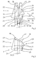
- the shoulder jacket 21 (FIG. 2) is formed from two separate jacket parts 22, 23.
- the shoulder stub 20 consists of two separate stub parts 24, 25. In each case a shell part 22, 23 and an adjoining neck part 24, 25 form a structural unit 26, 27.
- the two units 26, 27 describe the forming shoulder 4.
- An assembly 27 is removable from the other assembly 26 to remove the filling tube 7 or only a part thereof transverse to the transport direction 12 from the forming shoulder 4 can.
- the filling tube 7 consists of two with their interior mutually aligned grooves 28, 29, wherein a groove 29 is detachably connected to the other groove 28.
- the connection is a device 30 for adjusting and locking the present between the two grooves 28, 29 distance 31.
- the detachable groove 29 is provided in the region of the adjacent edges 9 of the film tube 5.
- the rear assembly 26 is positioned towards the incoming film web 3.
- the front structural unit 27 is provided in the region of the adjacent edges 9 of the film tube 5 and is almost closed at the front, in order to place the edges 9 against each other.
- the device 30 also serves as means 32 for adjusting and fixing the distance 33 between the units 26, 27.
- a height adjustment 34 for adjusting and fixing the relative height of a unit 27 relative to the other unit 26 includes a plurality of holes in the grooves 28, 29 and plug-in modules 38 on the device 30.
- a linkage 36 With her a linkage 36 is connected.
- the deflection edge 18 of the assembly 27 is then achieved by lowering the plug-in module 38 and thus the linkage 36, wherein the entire assembly 27 is lowered. In this way, the part of the deflecting edge 18 located on the structural unit 27 is displaced in the direction 40 of the deflecting edge.
- the plug-in module 38 makes it possible to easily pull the channel 29 and the assembly 27 forwards (in the direction 39) so as to remove a metering screw (not shown) located in the filling tube 7 from the filling tube 7 laterally in the direction 39.
- a distance 31, 33 is provided between the shell parts 22, 23 and the nozzle parts 24, 25, which is spanned by means of a clamping material 41.
- an upper edge 42 of the clamping material 41 forms part of the deflection edge 18th
Landscapes
- Engineering & Computer Science (AREA)
- Mechanical Engineering (AREA)
- Containers And Plastic Fillers For Packaging (AREA)
- Paper (AREA)
- Auxiliary Devices For And Details Of Packaging Control (AREA)
Description
- Die Erfindung betrifft eine vertikale Schlauchbeutelmaschine gemäß dem Oberbegriff des Anspruchs 1.
- Vertikale Schlauchbeutelmaschinen dienen zum Erzeugen und Befüllen von Schlauchbeuteln und sind hinlänglich bekannt. An diesen Maschinen wird eine von einer Vorratsrolle abgewickelte Folienbahn mittels einer Formschulter zu einem vertikal ausgerichteten Folienschlauch umgeformt. Das untere Schlauchende wird befüllt, verschweißt und vom restlichen Folienschlauch abgetrennt, um derart befüllte Schlauchbeutel zu erzeugen.
- Es werden, je nach zu erreichenden Beuteltyp, unterschiedliche Formschultern eingesetzt. Im allgemeinen besteht eine Formschulter aus einem einteiligen Schultermantel, über den die ebene Folienbahn läuft, um zu einer Umlenkkante zu gelangen. An der Umlenkkante wird die Folienbahn sodann umgeformt, um sich nach Passieren der Umlenkkante als vertikal ausgerichteter Folienschlauch weiterzubewegen. Dabei durchläuft der Folienschlauch eine ringförmige Passage, welche außen von einem Schulterstutzen und von innen her von einem Füllrohr begrenzt wird.
- Diese herkömmliche Ausgestaltung hat den Nachteil, dass das Füllrohr nur dann seitlich entnommen werden kann, wenn die Formschulter zuvor entfernt wird.
- Aus der CH 490 995 ist ein Formelement zum Umformen einer Folienbahn zu einem Folienschlauch bekannt, das aus zwei separaten Teilen besteht. Diese Teile bilden zusammen ein äußeres Führungsteil. Um ein Füllrohr seitlich herausnehmen zu können, werden die Teile voneinander getrennt.
- Das bekannte Formelement hat den Nachteil, dass es für einen gleichmäßigen Folieneinlauf weniger geeignet ist, da die einlaufende Folienbahn kaum gestützt wird.
- Aus der DE 38 41 056 A1 ist eine vertikale Schlauchbeutelmaschine gemäß dem Oberbegriff des Anspruchs 1 bekannt, wobei eine geteilte Formschulter eingesetzt wird, um dünne Folien für warmes Packgut als Verpackungsmaterial zu nutzen.
- Die Formschulter hat den Nachteil, dass sie nicht größenverstellbar ist.
- Der Erfindung liegt die Aufgabe zugrunde, eine vertikale Schlauchbeutelmaschine gemäß dem Oberbegriff des Anspruchs 1 derart weiterzubilden, dass die Formschulter größenverstellbar ist.
- Gelöst ist diese Aufgabe gemäß Anspruch 1.
- Bei der vorgeschlagenen Schlauchbeutelmaschine wird der Schultermantel aus zwei separaten Mantelteilen und der Schulterstutzen aus zwei separaten Stutzenteilen gebildet, bilden jeweils ein Mantelteil und ein daran angrenzendes Stutzenteil eine Baueinheit, beschreiben die beiden Baueinheiten die Formschulter, und ist eine Baueinheit von der anderen Baueinheit abnehmbar, um das Füllrohr quer zur Transportrichtung aus der Formschulter entnehmen zu können.
- Die vorgeschlagene Schlauchbeutelmaschine hat den Vorteil, dass eine seitliche Füllrohrentnahme in einfacher Weise möglich ist, da die Baueinheiten voneinander getrennt werden können, um das Füllrohr dazwischen herauszunehmen. Die Folienbahn wird in zuverlässiger Weise gestützt, da jede Baueinheit ein Mantelteil aufweist, und die beiden Mantelteile einen herkömmlichen Schultermantel ausmachen oder zumindest in teilen ausreichend ersetzen. Die Baueinheiten sind zudem leicht handhabbar, was eine relativ schnelle Füllrohrentnahme ermöglicht.
- An der Schlauchbeutelmaschine ist eine hintere Baueinheit vorgesehen, welche zur einlaufenden Folienbahn hin positioniert ist, und eine vordere Baueinheit im Bereich der aneinanderliegenden Ränder des Folienschlauches. So ist zum einen ein ortsgenauer Lauf der Folienbahn zur Umlenkkante und zum anderen ein ortsgenauer Lauf der Ränder der Folienbahn hin zu einer Längssiegeleinrichtung erreicht.
- Mit einer vorgeschlagenen Einrichtung zum Verstellen und Fixieren des Abstandes zwischen den Baueinheiten wird erreicht, dass die Formschulter auf eine andere Folienbahnbreite und damit auf eine andere Beutelbreite eingestellt werden kann. Eine vorgeschlagene Höhenverstellung zum Verstellen und Fixieren der relativen Höhe einer Baueinheit relativ zur anderen Baueinheit dient dazu, dass beiden die Umlenkkante bildenden oberen Kanten der Mantelteile bzw. der Stutzenteile auch bei Vorliegen eines Abstandes zwischen den Bauteilen so eingestellt werden, dass die Kanten sich gegenseitig in ihrer Erstreckungsrichtung fortsetzen. Dadurch ist die Formschulter bezüglich ihrer Größe verstellbar.
- In einer vorteilhaften Ausgestaltung kann ein Abstand zwischen den Mantelteilen oder den Baueinheiten mittels eines Spannmaterials, insbesondere eines Streifens überspannt werden, wobei ein Rand des Spannmaterials einen Teil der Umlenkkante bildet (Anspruch 2). Dann weist die Umlenkkante keine Lücke auf, was die Folienbahn sicherer umformt.
- Die genaueste Folienführung ist analog Anspruch 3 erreicht, wenn die Mantelteile passgenau und dicht aneinander anliegen.
- Eine wesentliche Verbesserung der Servicefreundlichkeit der Schlauchbeutelmaschine ist erreicht, wenn gemäß Anspruch 4 das Füllrohr aus zwei mit ihrem Inneren gegeneinander ausgerichteten lösbaren miteinander verbundenen Rinnen gebildet ist. Dann kann nach einem Öffnen der Formschulter zusätzlich das Füllrohr geöffnet werden, indem man seitlich eine Rinne abnimmt. Dies hat den großen Vorteil, dass eine im Füllrohr vorgesehene Dosierschnecke, die bei Pulverdosierungen sehr oft eingesetzt wird, seitlich aus dem Füllrohr entnommen werden kann. Ein umständliches, durch obere Bauteile im allgemeinen behindertes, nach oben Herausziehen einer relativ langen und schweren Dosierschnecke wird somit vermieden. Das seitliche Herausnehmen der Dosierschnecke hat zudem den Vorteil, dass der Raum oberhalb der Dosierschnecke für andere sinnvolle Aggregate genutzt werden kann, d. h. nicht mehr ausgespart werden muss. Oder dieser Raum kann gänzlich entfallen, was zu einer kompakteren Bauweise und damit zu einem geringeren Platzbedarf für die vertikale Schlauchbeutelmaschine führt.
- Ist gemäß Anspruch 5 eine Einrichtung zum Verstellen und Arretieren des zwischen den beiden Rinnen vorliegenden Abstandes vorgesehen, so kann mittels einer Abstandsverstellung das Füllrohr auf ein anderes Beutelformat eingestellt werden.
- Das Herausheben einer Förderschnecke aus dem Füllrohr erfolgt am einfachsten in Richtung zur Längssiegeleinrichtung hin, da dort maschinenbedingt ein entsprechender Freiraum vorkommt. Dies ist möglich, wenn analog Anspruch 6 die lösbare Rinne im Bereich der aneinanderliegenden Ränder des Folienschlauches vorgesehen ist.
- Im folgenden wird die Erfindung an Hand von Ausführungsbeispiele darstellenden Figuren näher beschrieben. Es zeigt:
- Figur 1
- in einer Seitenansicht eine vertikale Schlauchbeutelmaschine mit einer von einer Vorratsrolle abgewickelten Folienbahn, einer Formschulter zum Umformen der Folienbahn zu einem Folienschlauch, einer Längs- und einer Quersiegeleinrichtung zum Verschweißen des Folienschlauches, und einem Füllrohr zum Aufnehmen und Befüllen des Folienschlauches, wobei die Formschulter aus zwei Bauteilen gebildet ist, welche jeweils einen Mantelteil und einen Stutzenteil umfassen und das Füllrohr aus zwei Rinnen besteht;
- Figur 2
- in einer perspektivischen Ansicht die Formschulter mitsamt einem Teil der beiden Rinnen der Figur 1, sowie
- Figur 3
- in einer Seitenansicht eine aus zwei Bauteilen bestehende Formschulter, wobei der Abstand zwischen den Bauteilen einstellbar ist.
- Bei einer vertikalen Schlauchbeutelmaschine 1 wird eine Folienbahn 3 von einer Vorratsrolle 2 abgewickelt (Figur 1). Eine Formschulter 4 dient zum Umformen der Folienbahn 3 zu einem Folienschlauch 5. Ein Folienabzug 6 dient zum Weitertransportieren der Folienbahn 3 und des Folienschlauches 5. Ein vertikal ausgerichtetes Füllrohr 7 ist zum Aufnehmen und Befüllen des Folienschlauches 5 vorgesehen. Eine Längssiegeleinrichtung 8 dient zum Verschweißen der Ränder 9 der Folienbahn 3 und damit zum Erzeugen einer Längssiegelnaht 10 des Folienschlauches 5. Eine Quersiegeleinrichtung 11 mit gegeneinander beweglichen, den Folienschlauch 5 quer zu seiner Transportrichtung 12 verschweißenden Schweißbacken 13 ist zum Erzeugen von Kopfnähten 14 und Bodennähten 15 an Schlauchbeuteln 16 vorgesehen.
- Eine Trenneinrichtung 17 dient zum Abtrennen der Schlauchbeutel 16 vom Folienschlauch 5. Die Formschulter 4 weist eine Umlenkkante 18 an einem oberen Rand 19 eines das Füllrohr 7 umgebenden Schulterstutzen 20 auf, ebenso einen an der gekrümmten Umlenkkante 18 ansetzenden, von der Umlenkkante 18 nach außen weg weisenden Schultermantel 21. Der Schultermantel 21 (Figur 2) wird aus zwei separaten Mantelteilen 22, 23 gebildet. Der Schulterstutzen 20 besteht aus zwei separaten Stutzenteilen 24, 25. Jeweils ein Mantelteil 22, 23 und ein daran angrenzendes Stutzenteil 24, 25 bilden eine Baueinheit 26, 27. Die beiden Baueinheiten 26, 27 beschreiben die Formschulter 4. Eine Baueinheit 27 ist von der anderen Baueinheit 26 abnehmbar, um das Füllrohr 7 oder nur einen Teil davon quer zur Transportrichtung 12 aus der Formschulter 4 entnehmen zu können.
- Das Füllrohr 7 besteht aus zwei mit ihrem Inneren gegeneinander ausgerichteten Rinnen 28, 29, wobei eine Rinne 29 lösbar mit der anderen Rinne 28 verbunden ist. Als Verbindung dient eine Einrichtung 30 zum Verstellen und Arretieren des zwischen den beiden Rinnen 28, 29 vorliegenden Abstandes 31. Die lösbare Rinne 29 ist im Bereich der aneinanderliegenden Ränder 9 des Folienschlauches 5 vorgesehen. Die hintere Baueinheit 26 ist zur einlaufenden Folienbahn 3 hin positioniert. Die vordere Baueinheit 27 ist im Bereich der aneinanderliegenden Ränder 9 des Folienschlauches 5 vorgesehen und ist vorne nahezu geschlossen, um die Ränder 9 gegeneinanderzulegen. Die Einrichtung 30 dient auch als Einrichtung 32 zum Verstellen und Fixieren des Abstandes 33 zwischen den Baueinheiten 26, 27. Eine Höhenverstellung 34 zum Verstellen und Fixieren der relativen Höhe einer Baueinheit 27 relativ zur anderen Baueinheit 26 enthält eine Vielzahl an Bohrungen in den Rinnen 28, 29 und Steckmodule 38 an der Einrichtung 30. Mit ihr ist ein Gestänge 36 verbunden. Durch eine Abstandseinstellung an einem Drehgewinde 37 wird der Abstand 31 der Rinnen 28, 29 in Richtung 39 z. B. auf eine größere Beutelbreite eingestellt. Die Umlenkkante 18 der Baueinheit 27 wird daraufhin durch Tiefersetzen des Steckmoduls 38 und damit des Gestänges 36 erreicht, wobei die gesamte Baueinheit 27 tiefergesetzt wird. Derart wird der an der Baueinheit 27 befindliche Teil der Umlenkkante 18 in Richtung 40 der Umlenkkante verschoben. Das Steckmodul 38 erlaubt es, die Rinne 29 und die Baueinheit 27 in einfacher Weise nach vorne (in Richtung 39) abzuziehen, um derart eine im Füllrohr 7 befindliche (nicht dargestellte) Dosierschnecke seitlich in Richtung 39 aus dem Füllrohr 7 zu entnehmen.
- Beim Ausführungsbeispiel der Figur 2 ist zwischen den Mantelteilen 22, 23 und den Stutzenteilen 24, 25 ein Abstand 31, 33 vorgesehen, welcher mittels eines Spannmaterials 41 überspannt ist. Dabei bildet ein oberer Rand 42 des Spannmaterials 41 einen Teil der Umlenkkante 18.
- Beim Ausführungsbeispiel der Figur 3 dient als Spannmaterial 41 zum Überbrücken der Umlenkkante 18 ein Streifen, der auf einem Rad 47 abgestützt ist und die Abstände 31, 33 sind gleich. Ansonsten gilt das für Figur 2 gesagte.
- 1
- Schlauchbeutelmaschine
- 2
- Vorratsrolle
- 3
- Folienbahn
- 4
- Formschulter
- 5
- Folienschlauch
- 6
- Folienabzug
- 7
- Füllrohr
- 8
- Längssiegeleinrichtung
- 9
- Rand
- 10
- Längssiegelnaht
- 11
- Quersiegeleinrichtung
- 12
- Transportrichtung
- 13
- Schweißbacke
- 14
- Kopfnaht
- 15
- Bodennaht
- 16
- Schlauchbeutel
- 17
- Trenneinrichtung
- 18
- Umlenkkante
- 19
- oberer Rand
- 20
- Schulterstutzen
- 21
- Schultermantel
- 22, 23
- Mantelteil
- 24, 25
- Stutzenteil
- 26, 27
- Baueinheit
- 28, 29
- Rinne
- 30
- Einrichtung zum Verstellen
- 31
- Abstand
- 32
- Einrichtung zum Verstellen
- 33
- Abstand
- 34
- Höhenverstellung
- 36
- Gestänge
- 37
- Drehgewinde
- 38
- Steckmodul
- 39, 40
- Richtung
- 41
- Spannmaterial
- 42
- oberer Rand
- 47
- Rad
Claims (6)
- Vertikale Schlauchbeutelmaschine (1) mit einer von einer Vorratsrolle (2) abgewickelten Folienbahn (3), einer Formschulter (4) zum Umformen der Folienbahn (3) zu einem Folienschlauch (5), einen Folienabzug (6) zum Weitertransportieren der Folienbahn (3) und des Folienschlauches (5), einem vertikal ausgerichteten Füllrohr (7) zum Aufnehmen und Befüllen des Folienschlauches (5), einer Längssiegeleinrichtung (8) zum Verschweißen der Ränder (9) der Folienbahn (3) und damit zum Erzeugen einer Längssiegelnaht (10) des Folienschlauches (5), einer Quersiegeleinrichtung (11) mit gegeneinander beweglichen, den Folienschlauch (5) quer zu seiner Transportrichtung (12) verschweißenden Schweißbacken (13) zum Erzeugen von Kopfnähten (14) und Bodennähten (15) an Schlauchbeuteln (16), und einer Trenneinrichtung (17) zum Abtrennen der Schlauchbeutel (16) vom Folienschlauch (5), wobei die Formschulter (4) eine Umlenkkante (18) an einem oberen Rand (19) eines das Füllrohr (7) umgebenden Schulterstutzens (20) und einem an der gekrümmten Umlenkkante (18) ansetzenden, von der Umlenkkante (18) nach außen weg weisenden Schultermantel (21) aufweist, der Schultermantel (21) aus zwei separaten Mantelteilen (22, 23) gebildet wird, der Schulterstutzen (20) aus zwei separaten Stutzenteilen (24, 25) gebildet wird, jeweils ein Mantelteil (22, 23) und ein daran angrenzendes Stutzenteil (24, 25) eine Baueinheit (26, 27) bilden, die beiden Baueinheiten (26, 27) die Formschulter (4) beschreiben, und eine Baueinheit (27) von der anderen Baueinheit (26) abnehmbar ist, um das Füllrohr (7) quer zur Transportrichtung (12) aus der Formschulter (4) entnehmen zu können, sowie eine hintere Baueinheit (26) vorgesehen ist, welche zur einlaufenden Folienbahn (3) hin positioniert ist, und eine vordere Baueinheit (27) im Bereich der aneinanderliegenden Ränder (9) des Folienschlauches (5) vorgesehen ist, dadurch gekennzeichnet, dass eine Einrichtung (32) zum Verstellen und Fixieren des Abstandes (33) zwischen den Baueinheiten (26, 27) vorgesehen ist, und dass eine Höhenverstellung (34) zum Verstellen und Fixieren der relativen Höhe einer Baueinheit (27) relativ zur anderen Baueinheit (26) vorgesehen ist.
- Schlauchbeutelmaschine nach Anspruch 1, dadurch gekennzeichnet, dass zwischen den Mantelteilen (22, 23) oder den Baueinheiten (26, 27) ein Abstand (31, 33) vorgesehen ist, welcher mitte!s eines Spannmaterials (41), insbesondere eines Streifens überspannt ist, und dass ein Rand (42) des Spannmaterials (41) einen Teil der Umlenkkante (18) bildet.
- Schlauchbeutelmaschine nach Anspruch 1 oder Anspruch 2, dadurch gekennzeichnet, dass die Mantelteile (22, 23) passgenau und dicht aneinander anliegen.
- Schlauchbeutelmaschine nach einem der Ansprüche 1 bis 3, dadurch gekennzeichnet, dass das Füllrohr (7) aus zwei mit ihrem Inneren gegeneinander ausgerichteten Rinnen (28, 29) gebildet ist, und dass eine Rinne (29) lösbar mit der anderen Rinne (28) verbunden ist.
- Schlauchbeutelmaschine nach Anspruch 4, dadurch gekennzeichnet, dass eine Einrichtung (30) zum Verstellen und Arretieren des zwischen den beiden Rinnen (28, 29) vorliegenden Abstandes (31) vorgesehen ist.
- Schlauchbeutelmaschine nach Anspruch 5, dadurch gekennzeichnet, dass die lösbare Rinne (29) im Bereich der aneinanderliegenden Ränder (9) des Folienschlauches (5) vorgesehen ist.
Applications Claiming Priority (2)
| Application Number | Priority Date | Filing Date | Title |
|---|---|---|---|
| DE10330852A DE10330852A1 (de) | 2003-07-09 | 2003-07-09 | Vertikale Schlauchbeutelmaschine |
| DE10330852 | 2003-07-09 |
Publications (3)
| Publication Number | Publication Date |
|---|---|
| EP1495966A2 EP1495966A2 (de) | 2005-01-12 |
| EP1495966A3 EP1495966A3 (de) | 2005-01-26 |
| EP1495966B1 true EP1495966B1 (de) | 2007-01-03 |
Family
ID=33441668
Family Applications (1)
| Application Number | Title | Priority Date | Filing Date |
|---|---|---|---|
| EP04015432A Expired - Lifetime EP1495966B1 (de) | 2003-07-09 | 2004-07-01 | Vertikale Schlauchbeutelmaschine |
Country Status (5)
| Country | Link |
|---|---|
| US (1) | US7069707B2 (de) |
| EP (1) | EP1495966B1 (de) |
| AT (1) | ATE350278T1 (de) |
| DE (2) | DE10330852A1 (de) |
| ES (1) | ES2279259T3 (de) |
Families Citing this family (11)
| Publication number | Priority date | Publication date | Assignee | Title |
|---|---|---|---|---|
| DE102004016500A1 (de) * | 2004-04-03 | 2005-10-20 | Rovema Gmbh | Vertikale Schlauchbeutelmaschine zum Verpacken horizontal ausgerichteter Gegenstandsgruppen |
| DE102007012862B3 (de) * | 2007-03-17 | 2008-06-26 | Mediseal Gmbh | Werkzeug für eine Schlauchbeutelmaschine zum Umformen eines Hüllmaterialstreifens in einen Schlauch |
| DE102007041808B4 (de) * | 2007-03-17 | 2009-04-23 | Mediseal Gmbh | Werkzeug für eine Schlauchbeutelmaschine zum Umformen eines Hüllmaterialstreifens in einen Schlauch |
| DE102007049210B3 (de) * | 2007-10-13 | 2008-10-09 | Mediseal Gmbh | Werkzeug für eine Schlauchbeutelmaschine zum Umformen eines Hüllmaterialstreifens in einen Schlauch |
| US7987655B2 (en) * | 2008-04-22 | 2011-08-02 | Rovema Packaging Machines, Lp | Tubular bagging machine and method |
| US8539741B2 (en) * | 2010-02-10 | 2013-09-24 | Triangle Package Machinery Company | Seal and cut method and apparatus |
| DE102011004297B3 (de) * | 2011-02-17 | 2012-05-31 | Henry Drut | Mehrteilige Formschulter |
| ITMI20120388A1 (it) * | 2011-03-17 | 2012-09-18 | Tna Australia Pty Ltd | Dispositivo di formatura per confezionatrice |
| NL2007785C2 (en) * | 2011-11-14 | 2013-05-16 | Fuji Seal Europe Bv | Mandrel to be suspended in a sleeving device for arranging sleeves around containers, sleeving device and method for arranging sleeves around containers. |
| US10358244B2 (en) | 2015-10-26 | 2019-07-23 | Triangle Package Machinery Co. | Rotatable sealing jaw assembly for a form, fill and seal machine |
| PL3981696T3 (pl) * | 2016-05-05 | 2024-11-18 | Amcor Flexibles North America, Inc. | Owijarka przepływowa z rurą formującą |
Family Cites Families (12)
| Publication number | Priority date | Publication date | Assignee | Title |
|---|---|---|---|---|
| US3296770A (en) * | 1965-01-13 | 1967-01-10 | Russell W Wilson | Adjustable package-forming machine |
| US3415171A (en) * | 1967-05-10 | 1968-12-10 | Russell W. Wilson | Adjustable package-forming machine |
| ES361291A1 (es) * | 1967-12-14 | 1970-11-01 | Vnh Gebr Aquarius Nv Maschf | Aparato para plegar un material laminado en un tubo. |
| US4924655A (en) * | 1987-06-29 | 1990-05-15 | Baxter Travenol Laboratories, Inc. | Film guide system |
| US4829745A (en) * | 1987-12-07 | 1989-05-16 | The Dow Chemical Company | Tube spreader for removing wrinkles in tube stock |
| CH674174A5 (de) * | 1987-12-09 | 1990-05-15 | Kustner Ind Sa | |
| JP2905223B2 (ja) | 1989-08-11 | 1999-06-14 | 株式会社川島製作所 | 縦型製袋充填包装機の万能製袋器 |
| US5930983A (en) * | 1992-06-29 | 1999-08-03 | Pacmac, Inc. | Form, fill and seal packaging machine with bag squeezer and method |
| DE19628098A1 (de) * | 1996-07-12 | 1998-01-15 | Rovema Gmbh | Vertikale Schlauchbeutelmaschine und Verfahren zum Betreiben einer Schlauchbeutelmaschine |
| GB9626745D0 (en) * | 1996-12-23 | 1997-02-12 | Ishida Seisakusho | Form-fill-seal packaging machine |
| DE10330294A1 (de) * | 2003-07-04 | 2005-01-20 | Rovema - Verpackungsmaschinen Gmbh | Vertikale Schlauchbeutelmaschine |
| CN101335473B (zh) * | 2003-07-24 | 2011-04-27 | 株式会社日立制作所 | 发电机 |
-
2003
- 2003-07-09 DE DE10330852A patent/DE10330852A1/de not_active Withdrawn
-
2004
- 2004-06-30 US US10/882,113 patent/US7069707B2/en not_active Expired - Lifetime
- 2004-07-01 ES ES04015432T patent/ES2279259T3/es not_active Expired - Lifetime
- 2004-07-01 DE DE502004002501T patent/DE502004002501D1/de not_active Expired - Fee Related
- 2004-07-01 EP EP04015432A patent/EP1495966B1/de not_active Expired - Lifetime
- 2004-07-01 AT AT04015432T patent/ATE350278T1/de not_active IP Right Cessation
Also Published As
| Publication number | Publication date |
|---|---|
| US7069707B2 (en) | 2006-07-04 |
| US20050044822A1 (en) | 2005-03-03 |
| ES2279259T3 (es) | 2007-08-16 |
| DE10330852A1 (de) | 2005-02-10 |
| EP1495966A3 (de) | 2005-01-26 |
| ATE350278T1 (de) | 2007-01-15 |
| DE502004002501D1 (de) | 2007-02-15 |
| EP1495966A2 (de) | 2005-01-12 |
Similar Documents
| Publication | Publication Date | Title |
|---|---|---|
| EP1060072B1 (de) | Vorrichtung zum herstellen von schlauchbeutelpackungen | |
| DE3905605C2 (de) | Verfahren und Vorrichtung zum Herstellen, Füllen und Verschließen von Beuteln | |
| EP0781707B1 (de) | Quernaht-Schweissvorrichtung für eine vertikale Schlauchbeutelmaschine | |
| DE2415228C2 (de) | Vorrichtung zum Herstellen und Füllen von Säcken aus thermisch verschweißbarem Material | |
| EP3551446B1 (de) | Sackherstellvorrichtung und verfahren | |
| DE3612196A1 (de) | Vorrichtung zum herstellen von beutelpackungen mit entnahmestutzen | |
| DE3824753C2 (de) | Beutel, Verfahren zu dessen Herstellung und Vorrichtung zur Herstellung von Beuteln | |
| EP1689643B1 (de) | Kontinuierlich arbeitende vertikale schlauchbeutelmaschine | |
| DE19515719C2 (de) | Vorrichtung zum Verpacken von Gegenständen in Schlauchbeutel | |
| EP1495965B1 (de) | Vertikale Schlauchbeutelmaschine | |
| DE10330852A1 (de) | Vertikale Schlauchbeutelmaschine | |
| DE19630420B4 (de) | Verfahren zum Betreiben einer Schlauchbeutelmaschine | |
| DE1921234B2 (de) | Vorrichtung zur herstellung von verpackungen mit flachem boden aus einem fortlaufenden folienstreifen | |
| DE60318887T2 (de) | Flexible verpackung | |
| DE3006129A1 (de) | Maschine zum fuellen und verschliessen von saecken aus kunststoff, voprzugsweise von seitenfaltensaecken oder flachsaecken | |
| DE2307354C3 (de) | ||
| DE19549759B4 (de) | Vertikale Schlauchbeutelmaschine | |
| DE10251072A1 (de) | Formschulter zur Umformung einer Folienbahn | |
| DE1218332B (de) | Maschine zum Herstellen, Fuellen und Verschliessen quaderfoermiger Packungen aus einem fortlaufenden Band aus Papier mit heisssiegelfaehiger Beschichtung | |
| DE19515718A1 (de) | Vorrichtung zum Verpacken von Gegenständen in einen Schlauchbeutel | |
| EP1052170B9 (de) | Vertikale Schlauchbeutelmaschine | |
| DE2307354A1 (de) | Verfahren und vorrichtung zur ausstattung von schlauchbeuteln mit einem clip-verschluss | |
| DE2440491C2 (de) | Vorrichtung zur Herstellung von Kreuzboden-Ventilsäcken | |
| EP3328739B1 (de) | Verfahren zum betrieb einer schlauchbeutelmaschine zur herstellung von beuteln mit einer boden-quernaht und einer davon unterschiedlichen kopf-quernaht | |
| DE10304913B4 (de) | Vorrichtung zum Aufnehmen eines Folienschlauches und vertikale Schlauchbeutelmaschine mit einer derartigen Vorrichtung |
Legal Events
| Date | Code | Title | Description |
|---|---|---|---|
| PUAI | Public reference made under article 153(3) epc to a published international application that has entered the european phase |
Free format text: ORIGINAL CODE: 0009012 |
|
| PUAL | Search report despatched |
Free format text: ORIGINAL CODE: 0009013 |
|
| AK | Designated contracting states |
Kind code of ref document: A2 Designated state(s): AT BE BG CH CY CZ DE DK EE ES FI FR GB GR HU IE IT LI LU MC NL PL PT RO SE SI SK TR |
|
| AX | Request for extension of the european patent |
Extension state: AL HR LT LV MK |
|
| AK | Designated contracting states |
Kind code of ref document: A3 Designated state(s): AT BE BG CH CY CZ DE DK EE ES FI FR GB GR HU IE IT LI LU MC NL PL PT RO SE SI SK TR |
|
| AX | Request for extension of the european patent |
Extension state: AL HR LT LV MK |
|
| 17P | Request for examination filed |
Effective date: 20050722 |
|
| AKX | Designation fees paid |
Designated state(s): AT BE BG CH CY CZ DE DK EE ES FI FR GB GR HU IE IT LI LU MC NL PL PT RO SE SI SK TR |
|
| GRAP | Despatch of communication of intention to grant a patent |
Free format text: ORIGINAL CODE: EPIDOSNIGR1 |
|
| GRAS | Grant fee paid |
Free format text: ORIGINAL CODE: EPIDOSNIGR3 |
|
| GRAA | (expected) grant |
Free format text: ORIGINAL CODE: 0009210 |
|
| AK | Designated contracting states |
Kind code of ref document: B1 Designated state(s): AT BE BG CH CY CZ DE DK EE ES FI FR GB GR HU IE IT LI LU MC NL PL PT RO SE SI SK TR |
|
| PG25 | Lapsed in a contracting state [announced via postgrant information from national office to epo] |
Ref country code: PL Free format text: LAPSE BECAUSE OF FAILURE TO SUBMIT A TRANSLATION OF THE DESCRIPTION OR TO PAY THE FEE WITHIN THE PRESCRIBED TIME-LIMIT Effective date: 20070103 Ref country code: FI Free format text: LAPSE BECAUSE OF FAILURE TO SUBMIT A TRANSLATION OF THE DESCRIPTION OR TO PAY THE FEE WITHIN THE PRESCRIBED TIME-LIMIT Effective date: 20070103 Ref country code: IE Free format text: LAPSE BECAUSE OF FAILURE TO SUBMIT A TRANSLATION OF THE DESCRIPTION OR TO PAY THE FEE WITHIN THE PRESCRIBED TIME-LIMIT Effective date: 20070103 Ref country code: SI Free format text: LAPSE BECAUSE OF FAILURE TO SUBMIT A TRANSLATION OF THE DESCRIPTION OR TO PAY THE FEE WITHIN THE PRESCRIBED TIME-LIMIT Effective date: 20070103 Ref country code: DK Free format text: LAPSE BECAUSE OF FAILURE TO SUBMIT A TRANSLATION OF THE DESCRIPTION OR TO PAY THE FEE WITHIN THE PRESCRIBED TIME-LIMIT Effective date: 20070103 |
|
| REG | Reference to a national code |
Ref country code: GB Ref legal event code: FG4D Free format text: NOT ENGLISH |
|
| REF | Corresponds to: |
Ref document number: 502004002501 Country of ref document: DE Date of ref document: 20070215 Kind code of ref document: P |
|
| REG | Reference to a national code |
Ref country code: IE Ref legal event code: FG4D Free format text: LANGUAGE OF EP DOCUMENT: GERMAN |
|
| PG25 | Lapsed in a contracting state [announced via postgrant information from national office to epo] |
Ref country code: SE Free format text: LAPSE BECAUSE OF FAILURE TO SUBMIT A TRANSLATION OF THE DESCRIPTION OR TO PAY THE FEE WITHIN THE PRESCRIBED TIME-LIMIT Effective date: 20070403 |
|
| PG25 | Lapsed in a contracting state [announced via postgrant information from national office to epo] |
Ref country code: BG Free format text: LAPSE BECAUSE OF FAILURE TO SUBMIT A TRANSLATION OF THE DESCRIPTION OR TO PAY THE FEE WITHIN THE PRESCRIBED TIME-LIMIT Effective date: 20070404 |
|
| GBT | Gb: translation of ep patent filed (gb section 77(6)(a)/1977) |
Effective date: 20070329 |
|
| PG25 | Lapsed in a contracting state [announced via postgrant information from national office to epo] |
Ref country code: PT Free format text: LAPSE BECAUSE OF FAILURE TO SUBMIT A TRANSLATION OF THE DESCRIPTION OR TO PAY THE FEE WITHIN THE PRESCRIBED TIME-LIMIT Effective date: 20070604 |
|
| ET | Fr: translation filed | ||
| REG | Reference to a national code |
Ref country code: ES Ref legal event code: FG2A Ref document number: 2279259 Country of ref document: ES Kind code of ref document: T3 |
|
| REG | Reference to a national code |
Ref country code: IE Ref legal event code: FD4D |
|
| PLBE | No opposition filed within time limit |
Free format text: ORIGINAL CODE: 0009261 |
|
| STAA | Information on the status of an ep patent application or granted ep patent |
Free format text: STATUS: NO OPPOSITION FILED WITHIN TIME LIMIT |
|
| PG25 | Lapsed in a contracting state [announced via postgrant information from national office to epo] |
Ref country code: SK Free format text: LAPSE BECAUSE OF FAILURE TO SUBMIT A TRANSLATION OF THE DESCRIPTION OR TO PAY THE FEE WITHIN THE PRESCRIBED TIME-LIMIT Effective date: 20070103 |
|
| 26N | No opposition filed |
Effective date: 20071005 |
|
| PG25 | Lapsed in a contracting state [announced via postgrant information from national office to epo] |
Ref country code: RO Free format text: LAPSE BECAUSE OF FAILURE TO SUBMIT A TRANSLATION OF THE DESCRIPTION OR TO PAY THE FEE WITHIN THE PRESCRIBED TIME-LIMIT Effective date: 20070103 Ref country code: CZ Free format text: LAPSE BECAUSE OF FAILURE TO SUBMIT A TRANSLATION OF THE DESCRIPTION OR TO PAY THE FEE WITHIN THE PRESCRIBED TIME-LIMIT Effective date: 20070103 |
|
| PG25 | Lapsed in a contracting state [announced via postgrant information from national office to epo] |
Ref country code: GR Free format text: LAPSE BECAUSE OF FAILURE TO SUBMIT A TRANSLATION OF THE DESCRIPTION OR TO PAY THE FEE WITHIN THE PRESCRIBED TIME-LIMIT Effective date: 20070404 Ref country code: MC Free format text: LAPSE BECAUSE OF NON-PAYMENT OF DUE FEES Effective date: 20070731 |
|
| PGFP | Annual fee paid to national office [announced via postgrant information from national office to epo] |
Ref country code: ES Payment date: 20080729 Year of fee payment: 5 |
|
| PG25 | Lapsed in a contracting state [announced via postgrant information from national office to epo] |
Ref country code: AT Free format text: LAPSE BECAUSE OF NON-PAYMENT OF DUE FEES Effective date: 20070701 |
|
| PGFP | Annual fee paid to national office [announced via postgrant information from national office to epo] |
Ref country code: FR Payment date: 20080715 Year of fee payment: 5 Ref country code: IT Payment date: 20080723 Year of fee payment: 5 Ref country code: NL Payment date: 20080716 Year of fee payment: 5 |
|
| PGFP | Annual fee paid to national office [announced via postgrant information from national office to epo] |
Ref country code: GB Payment date: 20080722 Year of fee payment: 5 |
|
| PG25 | Lapsed in a contracting state [announced via postgrant information from national office to epo] |
Ref country code: EE Free format text: LAPSE BECAUSE OF FAILURE TO SUBMIT A TRANSLATION OF THE DESCRIPTION OR TO PAY THE FEE WITHIN THE PRESCRIBED TIME-LIMIT Effective date: 20070103 |
|
| PGFP | Annual fee paid to national office [announced via postgrant information from national office to epo] |
Ref country code: BE Payment date: 20080814 Year of fee payment: 5 |
|
| REG | Reference to a national code |
Ref country code: CH Ref legal event code: PL |
|
| PG25 | Lapsed in a contracting state [announced via postgrant information from national office to epo] |
Ref country code: CH Free format text: LAPSE BECAUSE OF NON-PAYMENT OF DUE FEES Effective date: 20080731 Ref country code: LI Free format text: LAPSE BECAUSE OF NON-PAYMENT OF DUE FEES Effective date: 20080731 |
|
| PG25 | Lapsed in a contracting state [announced via postgrant information from national office to epo] |
Ref country code: CY Free format text: LAPSE BECAUSE OF FAILURE TO SUBMIT A TRANSLATION OF THE DESCRIPTION OR TO PAY THE FEE WITHIN THE PRESCRIBED TIME-LIMIT Effective date: 20070103 |
|
| PG25 | Lapsed in a contracting state [announced via postgrant information from national office to epo] |
Ref country code: LU Free format text: LAPSE BECAUSE OF NON-PAYMENT OF DUE FEES Effective date: 20070701 |
|
| PG25 | Lapsed in a contracting state [announced via postgrant information from national office to epo] |
Ref country code: TR Free format text: LAPSE BECAUSE OF FAILURE TO SUBMIT A TRANSLATION OF THE DESCRIPTION OR TO PAY THE FEE WITHIN THE PRESCRIBED TIME-LIMIT Effective date: 20070103 Ref country code: HU Free format text: LAPSE BECAUSE OF FAILURE TO SUBMIT A TRANSLATION OF THE DESCRIPTION OR TO PAY THE FEE WITHIN THE PRESCRIBED TIME-LIMIT Effective date: 20070704 |
|
| BERE | Be: lapsed |
Owner name: ROVEMA VERPACKUNGSMASCHINEN G.M.B.H. Effective date: 20090731 |
|
| GBPC | Gb: european patent ceased through non-payment of renewal fee |
Effective date: 20090701 |
|
| NLV4 | Nl: lapsed or anulled due to non-payment of the annual fee |
Effective date: 20100201 |
|
| REG | Reference to a national code |
Ref country code: FR Ref legal event code: ST Effective date: 20100331 |
|
| PG25 | Lapsed in a contracting state [announced via postgrant information from national office to epo] |
Ref country code: FR Free format text: LAPSE BECAUSE OF NON-PAYMENT OF DUE FEES Effective date: 20090731 |
|
| PG25 | Lapsed in a contracting state [announced via postgrant information from national office to epo] |
Ref country code: GB Free format text: LAPSE BECAUSE OF NON-PAYMENT OF DUE FEES Effective date: 20090701 |
|
| PG25 | Lapsed in a contracting state [announced via postgrant information from national office to epo] |
Ref country code: DE Free format text: LAPSE BECAUSE OF NON-PAYMENT OF DUE FEES Effective date: 20100202 Ref country code: BE Free format text: LAPSE BECAUSE OF NON-PAYMENT OF DUE FEES Effective date: 20090731 |
|
| REG | Reference to a national code |
Ref country code: ES Ref legal event code: FD2A Effective date: 20090702 |
|
| PG25 | Lapsed in a contracting state [announced via postgrant information from national office to epo] |
Ref country code: ES Free format text: LAPSE BECAUSE OF NON-PAYMENT OF DUE FEES Effective date: 20090702 |
|
| PG25 | Lapsed in a contracting state [announced via postgrant information from national office to epo] |
Ref country code: IT Free format text: LAPSE BECAUSE OF NON-PAYMENT OF DUE FEES Effective date: 20090701 |
|
| REG | Reference to a national code |
Ref country code: DE Ref legal event code: R082 Ref document number: 502004002501 Country of ref document: DE Representative=s name: ADVOTEC. PATENT- UND RECHTSANWAELTE, DE Effective date: 20110915 Ref country code: DE Ref legal event code: R081 Ref document number: 502004002501 Country of ref document: DE Owner name: ROVEMA GMBH, DE Free format text: FORMER OWNER: ROVEMA - VERPACKUNGSMASCHINEN GMBH, 35463 FERNWALD, DE Effective date: 20110915 |
|
| PG25 | Lapsed in a contracting state [announced via postgrant information from national office to epo] |
Ref country code: NL Free format text: LAPSE BECAUSE OF NON-PAYMENT OF DUE FEES Effective date: 20100201 |
|
| PGFP | Annual fee paid to national office [announced via postgrant information from national office to epo] |
Ref country code: DE Payment date: 20190923 Year of fee payment: 16 |
|
| REG | Reference to a national code |
Ref country code: DE Ref legal event code: R119 Ref document number: 502004002501 Country of ref document: DE |
|
| PG25 | Lapsed in a contracting state [announced via postgrant information from national office to epo] |
Ref country code: DE Free format text: LAPSE BECAUSE OF NON-PAYMENT OF DUE FEES Effective date: 20210202 |