EP1496010A1 - Automatischer Korkenzieher - Google Patents
Automatischer Korkenzieher Download PDFInfo
- Publication number
- EP1496010A1 EP1496010A1 EP04102851A EP04102851A EP1496010A1 EP 1496010 A1 EP1496010 A1 EP 1496010A1 EP 04102851 A EP04102851 A EP 04102851A EP 04102851 A EP04102851 A EP 04102851A EP 1496010 A1 EP1496010 A1 EP 1496010A1
- Authority
- EP
- European Patent Office
- Prior art keywords
- housing
- plug
- pusher member
- face
- electric motor
- Prior art date
- Legal status (The legal status is an assumption and is not a legal conclusion. Google has not performed a legal analysis and makes no representation as to the accuracy of the status listed.)
- Granted
Links
- 238000000605 extraction Methods 0.000 claims description 13
- 238000006073 displacement reaction Methods 0.000 claims description 6
- 230000000295 complement effect Effects 0.000 claims description 3
- 239000007799 cork Substances 0.000 abstract description 3
- 210000000056 organ Anatomy 0.000 description 4
- 230000006378 damage Effects 0.000 description 2
- 239000000463 material Substances 0.000 description 2
- 230000004308 accommodation Effects 0.000 description 1
- XAGFODPZIPBFFR-UHFFFAOYSA-N aluminium Chemical compound [Al] XAGFODPZIPBFFR-UHFFFAOYSA-N 0.000 description 1
- 229910052782 aluminium Inorganic materials 0.000 description 1
- 230000000694 effects Effects 0.000 description 1
Images




Classifications
-
- B—PERFORMING OPERATIONS; TRANSPORTING
- B67—OPENING, CLOSING OR CLEANING BOTTLES, JARS OR SIMILAR CONTAINERS; LIQUID HANDLING
- B67B—APPLYING CLOSURE MEMBERS TO BOTTLES JARS, OR SIMILAR CONTAINERS; OPENING CLOSED CONTAINERS
- B67B7/00—Hand- or power-operated devices for opening closed containers
- B67B7/02—Hand- or power-operated devices for opening closed containers for removing stoppers
- B67B7/04—Cork-screws
- B67B7/0405—Power-operated cork-screws, e.g. operated by an electric motor
Definitions
- the present invention relates to an automatic corkscrew intended for be placed on the neck of a bottle and adapted to perform automatically extracting the cap by screwing in the latter, a spin rotated by an electric motor, and the ejection of said plug by unscrewing the auger with respect to this plug.
- the apparatus described in this patent includes a dwelling cylindrical open on its face intended to be placed on the neck of the bottle, in which can engage the tendril. This accommodation is suitable to receive the cap during its extraction.
- the electric motor is mounted in a compartment outside said housing, so that the spin carried by this motor is located in the axis of this housing and that the engine can be move between a first stop constituted by an end of the opposite compartment to said face to be placed on the neck of the bottle and a second stop formed by the end of said opposite housing to said face.
- switching means are provided for controlling automatically starting the engine, rotating it in the opposite direction to eject the plug and stop the engine.
- These switching means comprise switches which are controlled by contact with the neck or by direct contact with the cork following the operating phase of the automatic corkscrew.
- a first disadvantage is that the spin is not guided in rotation between its free end and the electric motor.
- the plug because of its elastic and relative properties fragility, does not constitute a reliable device for operating the switches.
- the object of the present invention is to overcome the drawbacks of the above-mentioned apparatus, in particular by ensuring an efficient guiding of the tendril and by creating control means of the switches that are extremely reliable.
- the corkscrew of the type described above is characterized in that said cylindrical housing contains a pusher member, movable axially inside said housing at the same time as the plug and bearing on the cap during its ejection, the face of said organ pusher opposite its bearing face on the cap being adapted to cooperate with said switching means for controlling the operation of the motor electric.
- the pusher member is traversed axially by the spin by a helical passage complementary to the helical shape of the tendril, of so that the rotation of this twist moves said pusher member.
- This pusher member also makes it possible to axially guide the spin which guarantees that the latter engages rigorously in the axis of the stopper thus ensuring extraction of this plug in the optimal conditions.
- the displacement of the pusher member is guided by ribs arranged on the internal lateral face of the cylindrical housing, these ribs being engaged in notches on the periphery of the pusher organ.
- the cylindrical housing is extended outwards by a skirt of section wider than that of the housing that is intended to come to cap the neck of the bottle, a ring elastic strap being mounted inside this skirt, near the entrance of the housing, this ring being able to come into contact with the neck of the bottle, this ring cooperating with two control switches of the operation of the electric motor.
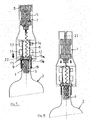
- the attached figures show an automatic corkscrew intended for be placed on the neck 1 of a bottle 2 and adapted to perform automatically extracting the cap 3 by screwing into the latter, a spin 4 driven in rotation by an electric motor 5, and the ejection of said plug 3 by unscrewing the twist 4 with respect to this plug 3.
- the automatic corkscrew comprises a cylindrical housing 6 (see in particular Figures 2 and 4) open on its face intended to be placed on the neck 1 of the bottle 2, in which can engage the spin 4.
- This housing 6 is able to receive the plug 3 (see Figures 8 and 9) during its extraction.
- the electric motor 5 is mounted in a compartment 7 outside the housing 6, so that the auger 4 carried by the engine 5 is located in the axis of the housing 6 and that the motor 5 can move between a first stop 8 (see FIGS. 4 and 5) constituted by one end of the compartment 7 opposed to the face 9 intended to be placed on the neck 1 of the bottle 2 and a second stop 10 (see FIGS. 7, 8 and 9) constituted by the end of housing 6 opposite to face 9.
- switches 11, 12, 13, 14 located outside the housing 6 are provided to automatically control the start-up of the motor 5, its rotation in one direction to extract the plug 3, its rotation in a reverse direction to eject the plug 3 and the stop of the engine 5.
- the cylindrical housing 6 contains an element rigid 15, for example aluminum or other rigid material pusher movable axially inside the housing 6 at the same time as the plug 3 and bearing on the plug 3 during its extraction and ejection.
- the face 15a of the pusher member 15 opposite its bearing face 15b on the plug 3 is able to cooperate with the switches to control the operation of the electric motor 5, as will be explained in more detail further.
- the pusher member 15 is traversed axially by the twist 4 by a helical passage 16 complementary to the helical shape of the twist 4, of so that the latter is screwed in this passage 16 and that the rotation of this twist 4 moves the push member 15.
- Figures 2 and 3 show that the displacement of the pusher member 15 is guided by ribs 17 arranged on the internal lateral face of the housing cylindrical 6. These ribs 17 are engaged in notches 18 performed on the periphery of the pusher member 15.
- FIG. 1 The figures further show that the cylindrical housing 6 is extended outwardly by a skirt 19 of wider section than that of the housing 6 which is intended to cap the neck 1 of the bottle 2.
- Figure 2 shows that an elastic ring 20 is mounted inside the skirt 19, close to the inlet 6a of the housing 6. This ring 20 is able to come into contact with the neck 1 of the bottle 2. This ring 20 cooperates with two switches 11, 12 of control of the operation of the electric motor 5, as one will explain it in more detail later.
- the pusher member 15 cooperates with a switch for command the stopping of the electric motor 5 at the end of the extraction phase of the plug, when the pusher member 15 is located at the end of stroke (see Figure 9) opposite the inlet 6a of the cylindrical housing 6.
- Figures 7 and 8 show in particular the displacement of the motor electrical 5 is guided by ribs such as 21 made on the face compartment 7. These ribs 21 are conductive and feed electrically the electric motor 5.
- the user engages the skirt 19 on the neck 1 of the bottle.
- the bottleneck of the bottle is supported on the ring 20 (see Figure 2) which closes the switch 11 and opens the switch 12.
- the twist 4 turns in the direction of screwing and is screwed into the plug 3 (see Figure 6).
- the motor 5 moves towards the housing 6 while being guided by the ribs such as 21.
- the motor 5 abuts against the stop 10 (see Figure 7). In this position, spin 4 continues to spin but the engine 5 can not move anymore.
- the spin 4 rotating extract the plug 3 of the bottle (see Figure 8) and the cap and the pushing member 15 in support on the latter, engage in housing 6.
- the pusher member 15 abuts against the end of the motor 5 after triggering the switch 13 which cuts the power supply of the engine.
- the user can then release the device from the neck of the bottle, which has for effect to return to idle position the ring 20 and put the switch 12 in the closed position.
- the engine then turns in direction reverse and the auger 4 is unscrewed relative to the plug 3 (see Figure 10).
- the motor 5 goes back to the stop 8.
- the rotation continues and the engine does not being able to move, the spin 4 rotating pushes the pusher member 15 towards the bottom (see Figure 11) which causes the ejection of the cap (see Figure 12). then of its displacement the pusher member 15 actuates the switch 14 which cuts the motor power supply 5.
Landscapes
- Engineering & Computer Science (AREA)
- Mechanical Engineering (AREA)
- Devices For Opening Bottles Or Cans (AREA)
- Iron Core Of Rotating Electric Machines (AREA)
Applications Claiming Priority (2)
| Application Number | Priority Date | Filing Date | Title |
|---|---|---|---|
| FR0350306 | 2003-07-08 | ||
| FR0350306A FR2857349B1 (fr) | 2003-07-08 | 2003-07-08 | Tire-bouchon automatique |
Publications (2)
| Publication Number | Publication Date |
|---|---|
| EP1496010A1 true EP1496010A1 (de) | 2005-01-12 |
| EP1496010B1 EP1496010B1 (de) | 2006-07-19 |
Family
ID=33443294
Family Applications (1)
| Application Number | Title | Priority Date | Filing Date |
|---|---|---|---|
| EP04102851A Expired - Lifetime EP1496010B1 (de) | 2003-07-08 | 2004-06-21 | Automatischer Korkenzieher |
Country Status (4)
| Country | Link |
|---|---|
| EP (1) | EP1496010B1 (de) |
| AT (1) | ATE333434T1 (de) |
| DE (1) | DE602004001553D1 (de) |
| FR (1) | FR2857349B1 (de) |
Cited By (3)
| Publication number | Priority date | Publication date | Assignee | Title |
|---|---|---|---|---|
| EP2218676A1 (de) * | 2009-02-12 | 2010-08-18 | Chun Ming Cheung | Elektrischer Korkenzieher |
| FR3029905A1 (fr) * | 2014-12-16 | 2016-06-17 | Psp | Tire-bouchon electrique autonome |
| DE102014019460A1 (de) | 2014-12-23 | 2016-06-23 | Eliquo Stulz Gmbh | Vorrichtung und Verfahren zur Extraktion von Phosphor aus Abwasser |
Citations (4)
| Publication number | Priority date | Publication date | Assignee | Title |
|---|---|---|---|---|
| FR2608143A1 (fr) * | 1986-12-15 | 1988-06-17 | Trebig | Tire-bouchon a moteur electrique |
| FR2683216A1 (fr) * | 1991-10-30 | 1993-05-07 | Shen Bo Chang | Tire-bouchon electrique. |
| US5372054A (en) * | 1993-06-14 | 1994-12-13 | Federighi, Sr.; George J. | Automatic cork extractor |
| US6321620B1 (en) * | 1998-04-15 | 2001-11-27 | Alberto Fabbro | Electrical corkscrew with depth penetration regulator |
-
2003
- 2003-07-08 FR FR0350306A patent/FR2857349B1/fr not_active Expired - Fee Related
-
2004
- 2004-06-21 EP EP04102851A patent/EP1496010B1/de not_active Expired - Lifetime
- 2004-06-21 DE DE602004001553T patent/DE602004001553D1/de not_active Expired - Lifetime
- 2004-06-21 AT AT04102851T patent/ATE333434T1/de not_active IP Right Cessation
Patent Citations (4)
| Publication number | Priority date | Publication date | Assignee | Title |
|---|---|---|---|---|
| FR2608143A1 (fr) * | 1986-12-15 | 1988-06-17 | Trebig | Tire-bouchon a moteur electrique |
| FR2683216A1 (fr) * | 1991-10-30 | 1993-05-07 | Shen Bo Chang | Tire-bouchon electrique. |
| US5372054A (en) * | 1993-06-14 | 1994-12-13 | Federighi, Sr.; George J. | Automatic cork extractor |
| US6321620B1 (en) * | 1998-04-15 | 2001-11-27 | Alberto Fabbro | Electrical corkscrew with depth penetration regulator |
Cited By (4)
| Publication number | Priority date | Publication date | Assignee | Title |
|---|---|---|---|---|
| EP2218676A1 (de) * | 2009-02-12 | 2010-08-18 | Chun Ming Cheung | Elektrischer Korkenzieher |
| US8578819B2 (en) | 2009-02-12 | 2013-11-12 | Chun Ming Cheung | Electric corkscrew |
| FR3029905A1 (fr) * | 2014-12-16 | 2016-06-17 | Psp | Tire-bouchon electrique autonome |
| DE102014019460A1 (de) | 2014-12-23 | 2016-06-23 | Eliquo Stulz Gmbh | Vorrichtung und Verfahren zur Extraktion von Phosphor aus Abwasser |
Also Published As
| Publication number | Publication date |
|---|---|
| EP1496010B1 (de) | 2006-07-19 |
| FR2857349A1 (fr) | 2005-01-14 |
| FR2857349B1 (fr) | 2005-10-14 |
| ATE333434T1 (de) | 2006-08-15 |
| DE602004001553D1 (de) | 2006-08-31 |
Similar Documents
| Publication | Publication Date | Title |
|---|---|---|
| US8667867B2 (en) | Powered bottle opening device with integrated wrapper cutter | |
| EP0122860B1 (de) | Verfahren und Vorrichtungen zum Einfetten von Spanngliedenden | |
| EP3019411B1 (de) | Verschlusskappe aus kunststoff | |
| FR2573303A1 (fr) | Mandrin a levier pour piece a main dentaire | |
| EP3310683A1 (de) | Axiale magnetische anziehungsvorrichtung | |
| FR2594494A1 (fr) | Pignon assiste par un levier dans un demarreur de moteur | |
| EP1496010B1 (de) | Automatischer Korkenzieher | |
| CA1164918A (fr) | Dispositif pour couper automatiquement l'alimentation electrique d'un moteur et son utilisation | |
| EP0805517B1 (de) | Verfahren und Verbindungsanordnung durch Isolationsschneidekontakt | |
| CA2139745A1 (fr) | Tire-bouchon electrique portable entierement automatique avec extraction et rejet du bouchon et de la capsule de surbouchage | |
| FR2667989A1 (fr) | Borne de connexion a vis imperdable et bornier utilisant des bornes de ce genre. | |
| FR2608143A1 (fr) | Tire-bouchon a moteur electrique | |
| FR2585588A1 (fr) | Appareil culinaire a couteau rotatif | |
| FR2720595A1 (fr) | Machine, notamment appareil électrique avec volume intérieur équipé d'un dispositif de ventilation et d'étanchéité qu'il faut protéger contre la corrosion et ventiler par au moins une ouverture. | |
| FR2458928A1 (de) | ||
| FR2660299A1 (fr) | Tire-bouchon electrique portable rechargeable sans fil. | |
| EP0020229B1 (de) | Elektrisches Anschlusselement des Isolations-Perforiertyps | |
| FR2669320A1 (fr) | Tire-bouchon mecanique. | |
| EP0674378B1 (de) | Motorgehäuse mit einer bei einem dürchlöcherten ablenkplattenförmigen Stopfen geschlossenen Flüssigentlehrungsöffnung, Stopfen und Anlasser für Motorfahrzeug | |
| WO2015150643A1 (fr) | Interrupteur electrique et appareil electrique associe | |
| FR2931716A1 (fr) | Appareil pour la pose d'un element a sertir | |
| FR2902295A1 (fr) | Procede et dispositif pour fabriquer des cigarettes par remplissage de tubes en papier avec du tabac. | |
| FR2920316A1 (fr) | Dispositif de projection de confettis declenche par l'ejection du bouchon d'une bouteille de boisson effervescente | |
| FR2686009A1 (fr) | Batteur-mixeur electrique a main. | |
| FR2584161A1 (fr) | Bouchon de transfert a telecommande manuelle |
Legal Events
| Date | Code | Title | Description |
|---|---|---|---|
| PUAI | Public reference made under article 153(3) epc to a published international application that has entered the european phase |
Free format text: ORIGINAL CODE: 0009012 |
|
| AK | Designated contracting states |
Kind code of ref document: A1 Designated state(s): AT BE BG CH CY CZ DE DK EE ES FI FR GB GR HU IE IT LI LU MC NL PL PT RO SE SI SK TR |
|
| AX | Request for extension of the european patent |
Extension state: AL HR LT LV MK |
|
| 17P | Request for examination filed |
Effective date: 20050428 |
|
| AKX | Designation fees paid |
Designated state(s): AT BE BG CH CY CZ DE DK EE ES FI FR GB GR HU IE IT LI LU MC NL PL PT RO SE SI SK TR |
|
| GRAP | Despatch of communication of intention to grant a patent |
Free format text: ORIGINAL CODE: EPIDOSNIGR1 |
|
| GRAS | Grant fee paid |
Free format text: ORIGINAL CODE: EPIDOSNIGR3 |
|
| GRAA | (expected) grant |
Free format text: ORIGINAL CODE: 0009210 |
|
| AK | Designated contracting states |
Kind code of ref document: B1 Designated state(s): AT BE BG CH CY CZ DE DK EE ES FI FR GB GR HU IE IT LI LU MC NL PL PT RO SE SI SK TR |
|
| PG25 | Lapsed in a contracting state [announced via postgrant information from national office to epo] |
Ref country code: IT Free format text: LAPSE BECAUSE OF FAILURE TO SUBMIT A TRANSLATION OF THE DESCRIPTION OR TO PAY THE FEE WITHIN THE PRESCRIBED TIME-LIMIT;WARNING: LAPSES OF ITALIAN PATENTS WITH EFFECTIVE DATE BEFORE 2007 MAY HAVE OCCURRED AT ANY TIME BEFORE 2007. THE CORRECT EFFECTIVE DATE MAY BE DIFFERENT FROM THE ONE RECORDED. Effective date: 20060719 Ref country code: AT Free format text: LAPSE BECAUSE OF FAILURE TO SUBMIT A TRANSLATION OF THE DESCRIPTION OR TO PAY THE FEE WITHIN THE PRESCRIBED TIME-LIMIT Effective date: 20060719 Ref country code: FI Free format text: LAPSE BECAUSE OF FAILURE TO SUBMIT A TRANSLATION OF THE DESCRIPTION OR TO PAY THE FEE WITHIN THE PRESCRIBED TIME-LIMIT Effective date: 20060719 Ref country code: IE Free format text: LAPSE BECAUSE OF FAILURE TO SUBMIT A TRANSLATION OF THE DESCRIPTION OR TO PAY THE FEE WITHIN THE PRESCRIBED TIME-LIMIT Effective date: 20060719 Ref country code: GB Free format text: LAPSE BECAUSE OF FAILURE TO SUBMIT A TRANSLATION OF THE DESCRIPTION OR TO PAY THE FEE WITHIN THE PRESCRIBED TIME-LIMIT Effective date: 20060719 Ref country code: NL Free format text: LAPSE BECAUSE OF FAILURE TO SUBMIT A TRANSLATION OF THE DESCRIPTION OR TO PAY THE FEE WITHIN THE PRESCRIBED TIME-LIMIT Effective date: 20060719 Ref country code: RO Free format text: LAPSE BECAUSE OF FAILURE TO SUBMIT A TRANSLATION OF THE DESCRIPTION OR TO PAY THE FEE WITHIN THE PRESCRIBED TIME-LIMIT Effective date: 20060719 Ref country code: PL Free format text: LAPSE BECAUSE OF FAILURE TO SUBMIT A TRANSLATION OF THE DESCRIPTION OR TO PAY THE FEE WITHIN THE PRESCRIBED TIME-LIMIT Effective date: 20060719 Ref country code: CZ Free format text: LAPSE BECAUSE OF FAILURE TO SUBMIT A TRANSLATION OF THE DESCRIPTION OR TO PAY THE FEE WITHIN THE PRESCRIBED TIME-LIMIT Effective date: 20060719 Ref country code: SK Free format text: LAPSE BECAUSE OF FAILURE TO SUBMIT A TRANSLATION OF THE DESCRIPTION OR TO PAY THE FEE WITHIN THE PRESCRIBED TIME-LIMIT Effective date: 20060719 Ref country code: SI Free format text: LAPSE BECAUSE OF FAILURE TO SUBMIT A TRANSLATION OF THE DESCRIPTION OR TO PAY THE FEE WITHIN THE PRESCRIBED TIME-LIMIT Effective date: 20060719 |
|
| REG | Reference to a national code |
Ref country code: GB Ref legal event code: FG4D Free format text: NOT ENGLISH |
|
| REG | Reference to a national code |
Ref country code: CH Ref legal event code: EP |
|
| REG | Reference to a national code |
Ref country code: IE Ref legal event code: FG4D Free format text: LANGUAGE OF EP DOCUMENT: FRENCH |
|
| REF | Corresponds to: |
Ref document number: 602004001553 Country of ref document: DE Date of ref document: 20060831 Kind code of ref document: P |
|
| PG25 | Lapsed in a contracting state [announced via postgrant information from national office to epo] |
Ref country code: SE Free format text: LAPSE BECAUSE OF FAILURE TO SUBMIT A TRANSLATION OF THE DESCRIPTION OR TO PAY THE FEE WITHIN THE PRESCRIBED TIME-LIMIT Effective date: 20061019 Ref country code: BG Free format text: LAPSE BECAUSE OF FAILURE TO SUBMIT A TRANSLATION OF THE DESCRIPTION OR TO PAY THE FEE WITHIN THE PRESCRIBED TIME-LIMIT Effective date: 20061019 Ref country code: DK Free format text: LAPSE BECAUSE OF FAILURE TO SUBMIT A TRANSLATION OF THE DESCRIPTION OR TO PAY THE FEE WITHIN THE PRESCRIBED TIME-LIMIT Effective date: 20061019 |
|
| PG25 | Lapsed in a contracting state [announced via postgrant information from national office to epo] |
Ref country code: DE Free format text: LAPSE BECAUSE OF FAILURE TO SUBMIT A TRANSLATION OF THE DESCRIPTION OR TO PAY THE FEE WITHIN THE PRESCRIBED TIME-LIMIT Effective date: 20061020 |
|
| PG25 | Lapsed in a contracting state [announced via postgrant information from national office to epo] |
Ref country code: ES Free format text: LAPSE BECAUSE OF FAILURE TO SUBMIT A TRANSLATION OF THE DESCRIPTION OR TO PAY THE FEE WITHIN THE PRESCRIBED TIME-LIMIT Effective date: 20061030 |
|
| PG25 | Lapsed in a contracting state [announced via postgrant information from national office to epo] |
Ref country code: PT Free format text: LAPSE BECAUSE OF FAILURE TO SUBMIT A TRANSLATION OF THE DESCRIPTION OR TO PAY THE FEE WITHIN THE PRESCRIBED TIME-LIMIT Effective date: 20061219 |
|
| NLV1 | Nl: lapsed or annulled due to failure to fulfill the requirements of art. 29p and 29m of the patents act | ||
| GBV | Gb: ep patent (uk) treated as always having been void in accordance with gb section 77(7)/1977 [no translation filed] |
Effective date: 20060719 |
|
| REG | Reference to a national code |
Ref country code: IE Ref legal event code: FD4D |
|
| PLBE | No opposition filed within time limit |
Free format text: ORIGINAL CODE: 0009261 |
|
| STAA | Information on the status of an ep patent application or granted ep patent |
Free format text: STATUS: NO OPPOSITION FILED WITHIN TIME LIMIT |
|
| 26N | No opposition filed |
Effective date: 20070420 |
|
| BERE | Be: lapsed |
Owner name: LENOIR, COLETTE Effective date: 20070630 |
|
| PG25 | Lapsed in a contracting state [announced via postgrant information from national office to epo] |
Ref country code: BE Free format text: LAPSE BECAUSE OF NON-PAYMENT OF DUE FEES Effective date: 20070630 |
|
| PG25 | Lapsed in a contracting state [announced via postgrant information from national office to epo] |
Ref country code: GR Free format text: LAPSE BECAUSE OF FAILURE TO SUBMIT A TRANSLATION OF THE DESCRIPTION OR TO PAY THE FEE WITHIN THE PRESCRIBED TIME-LIMIT Effective date: 20061020 |
|
| PG25 | Lapsed in a contracting state [announced via postgrant information from national office to epo] |
Ref country code: EE Free format text: LAPSE BECAUSE OF FAILURE TO SUBMIT A TRANSLATION OF THE DESCRIPTION OR TO PAY THE FEE WITHIN THE PRESCRIBED TIME-LIMIT Effective date: 20060719 |
|
| REG | Reference to a national code |
Ref country code: CH Ref legal event code: PL |
|
| PG25 | Lapsed in a contracting state [announced via postgrant information from national office to epo] |
Ref country code: LI Free format text: LAPSE BECAUSE OF NON-PAYMENT OF DUE FEES Effective date: 20080630 Ref country code: CH Free format text: LAPSE BECAUSE OF NON-PAYMENT OF DUE FEES Effective date: 20080630 |
|
| PGFP | Annual fee paid to national office [announced via postgrant information from national office to epo] |
Ref country code: MC Payment date: 20090626 Year of fee payment: 6 |
|
| PG25 | Lapsed in a contracting state [announced via postgrant information from national office to epo] |
Ref country code: CY Free format text: LAPSE BECAUSE OF FAILURE TO SUBMIT A TRANSLATION OF THE DESCRIPTION OR TO PAY THE FEE WITHIN THE PRESCRIBED TIME-LIMIT Effective date: 20060719 Ref country code: LU Free format text: LAPSE BECAUSE OF NON-PAYMENT OF DUE FEES Effective date: 20070621 |
|
| PG25 | Lapsed in a contracting state [announced via postgrant information from national office to epo] |
Ref country code: TR Free format text: LAPSE BECAUSE OF FAILURE TO SUBMIT A TRANSLATION OF THE DESCRIPTION OR TO PAY THE FEE WITHIN THE PRESCRIBED TIME-LIMIT Effective date: 20060719 Ref country code: HU Free format text: LAPSE BECAUSE OF FAILURE TO SUBMIT A TRANSLATION OF THE DESCRIPTION OR TO PAY THE FEE WITHIN THE PRESCRIBED TIME-LIMIT Effective date: 20070120 |
|
| PGFP | Annual fee paid to national office [announced via postgrant information from national office to epo] |
Ref country code: FR Payment date: 20100723 Year of fee payment: 7 |
|
| PG25 | Lapsed in a contracting state [announced via postgrant information from national office to epo] |
Ref country code: MC Free format text: LAPSE BECAUSE OF NON-PAYMENT OF DUE FEES Effective date: 20100630 |
|
| REG | Reference to a national code |
Ref country code: FR Ref legal event code: ST Effective date: 20120229 |
|
| PG25 | Lapsed in a contracting state [announced via postgrant information from national office to epo] |
Ref country code: FR Free format text: LAPSE BECAUSE OF NON-PAYMENT OF DUE FEES Effective date: 20110630 |