EP1496140A1 - Structure stratifiée et procédé pour sa production - Google Patents
Structure stratifiée et procédé pour sa production Download PDFInfo
- Publication number
- EP1496140A1 EP1496140A1 EP20030015495 EP03015495A EP1496140A1 EP 1496140 A1 EP1496140 A1 EP 1496140A1 EP 20030015495 EP20030015495 EP 20030015495 EP 03015495 A EP03015495 A EP 03015495A EP 1496140 A1 EP1496140 A1 EP 1496140A1
- Authority
- EP
- European Patent Office
- Prior art keywords
- layer
- layer structure
- substrate
- porous
- coating
- Prior art date
- Legal status (The legal status is an assumption and is not a legal conclusion. Google has not performed a legal analysis and makes no representation as to the accuracy of the status listed.)
- Withdrawn
Links
- 238000000034 method Methods 0.000 title claims description 13
- 238000001816 cooling Methods 0.000 claims abstract description 51
- 238000000576 coating method Methods 0.000 claims abstract description 30
- 239000011248 coating agent Substances 0.000 claims abstract description 26
- 239000000758 substrate Substances 0.000 claims description 43
- 239000011148 porous material Substances 0.000 claims description 28
- 238000002485 combustion reaction Methods 0.000 claims description 22
- 239000000919 ceramic Substances 0.000 claims description 14
- 239000002826 coolant Substances 0.000 claims description 13
- PXHVJJICTQNCMI-UHFFFAOYSA-N Nickel Chemical compound [Ni] PXHVJJICTQNCMI-UHFFFAOYSA-N 0.000 claims description 9
- 239000000463 material Substances 0.000 claims description 9
- 229910000601 superalloy Inorganic materials 0.000 claims description 8
- 229910017052 cobalt Inorganic materials 0.000 claims description 6
- 239000010941 cobalt Substances 0.000 claims description 6
- GUTLYIVDDKVIGB-UHFFFAOYSA-N cobalt atom Chemical compound [Co] GUTLYIVDDKVIGB-UHFFFAOYSA-N 0.000 claims description 6
- 238000004519 manufacturing process Methods 0.000 claims description 4
- XEEYBQQBJWHFJM-UHFFFAOYSA-N Iron Chemical compound [Fe] XEEYBQQBJWHFJM-UHFFFAOYSA-N 0.000 claims description 3
- 229910052759 nickel Inorganic materials 0.000 claims description 3
- 229910052727 yttrium Inorganic materials 0.000 claims description 3
- VWQVUPCCIRVNHF-UHFFFAOYSA-N yttrium atom Chemical compound [Y] VWQVUPCCIRVNHF-UHFFFAOYSA-N 0.000 claims description 3
- 238000007598 dipping method Methods 0.000 claims description 2
- 239000000203 mixture Substances 0.000 claims description 2
- 238000007750 plasma spraying Methods 0.000 claims description 2
- 239000010410 layer Substances 0.000 description 85
- 239000012720 thermal barrier coating Substances 0.000 description 6
- 238000005260 corrosion Methods 0.000 description 3
- BASFCYQUMIYNBI-UHFFFAOYSA-N platinum Chemical compound [Pt] BASFCYQUMIYNBI-UHFFFAOYSA-N 0.000 description 3
- 239000002002 slurry Substances 0.000 description 3
- 230000015572 biosynthetic process Effects 0.000 description 2
- 230000007797 corrosion Effects 0.000 description 2
- 230000001419 dependent effect Effects 0.000 description 2
- 239000006260 foam Substances 0.000 description 2
- 238000005192 partition Methods 0.000 description 2
- 239000011241 protective layer Substances 0.000 description 2
- 238000003466 welding Methods 0.000 description 2
- YPFNIPKMNMDDDB-UHFFFAOYSA-K 2-[2-[bis(carboxylatomethyl)amino]ethyl-(2-hydroxyethyl)amino]acetate;iron(3+) Chemical compound [Fe+3].OCCN(CC([O-])=O)CCN(CC([O-])=O)CC([O-])=O YPFNIPKMNMDDDB-UHFFFAOYSA-K 0.000 description 1
- 239000008186 active pharmaceutical agent Substances 0.000 description 1
- 238000004026 adhesive bonding Methods 0.000 description 1
- 239000012790 adhesive layer Substances 0.000 description 1
- 229910045601 alloy Inorganic materials 0.000 description 1
- 239000000956 alloy Substances 0.000 description 1
- PNEYBMLMFCGWSK-UHFFFAOYSA-N aluminium oxide Inorganic materials [O-2].[O-2].[O-2].[Al+3].[Al+3] PNEYBMLMFCGWSK-UHFFFAOYSA-N 0.000 description 1
- 239000011449 brick Substances 0.000 description 1
- BRPQOXSCLDDYGP-UHFFFAOYSA-N calcium oxide Chemical compound [O-2].[Ca+2] BRPQOXSCLDDYGP-UHFFFAOYSA-N 0.000 description 1
- 239000000292 calcium oxide Substances 0.000 description 1
- ODINCKMPIJJUCX-UHFFFAOYSA-N calcium oxide Inorganic materials [Ca]=O ODINCKMPIJJUCX-UHFFFAOYSA-N 0.000 description 1
- 238000005524 ceramic coating Methods 0.000 description 1
- 238000005229 chemical vapour deposition Methods 0.000 description 1
- 150000001875 compounds Chemical class 0.000 description 1
- 238000005566 electron beam evaporation Methods 0.000 description 1
- 239000012530 fluid Substances 0.000 description 1
- 239000000446 fuel Substances 0.000 description 1
- 238000010438 heat treatment Methods 0.000 description 1
- 238000007654 immersion Methods 0.000 description 1
- 239000011229 interlayer Substances 0.000 description 1
- 239000007788 liquid Substances 0.000 description 1
- 239000000395 magnesium oxide Substances 0.000 description 1
- CPLXHLVBOLITMK-UHFFFAOYSA-N magnesium oxide Inorganic materials [Mg]=O CPLXHLVBOLITMK-UHFFFAOYSA-N 0.000 description 1
- AXZKOIWUVFPNLO-UHFFFAOYSA-N magnesium;oxygen(2-) Chemical compound [O-2].[Mg+2] AXZKOIWUVFPNLO-UHFFFAOYSA-N 0.000 description 1
- 239000012528 membrane Substances 0.000 description 1
- 230000003647 oxidation Effects 0.000 description 1
- 238000007254 oxidation reaction Methods 0.000 description 1
- SIWVEOZUMHYXCS-UHFFFAOYSA-N oxo(oxoyttriooxy)yttrium Chemical compound O=[Y]O[Y]=O SIWVEOZUMHYXCS-UHFFFAOYSA-N 0.000 description 1
- 229910052697 platinum Inorganic materials 0.000 description 1
- 229910052761 rare earth metal Inorganic materials 0.000 description 1
- 150000002910 rare earth metals Chemical class 0.000 description 1
- 238000009419 refurbishment Methods 0.000 description 1
- 238000005245 sintering Methods 0.000 description 1
- 238000005476 soldering Methods 0.000 description 1
- 229910002076 stabilized zirconia Inorganic materials 0.000 description 1
- 230000008646 thermal stress Effects 0.000 description 1
- 230000007704 transition Effects 0.000 description 1
- 238000007740 vapor deposition Methods 0.000 description 1
- 229910001233 yttria-stabilized zirconia Inorganic materials 0.000 description 1
Images

Classifications
-
- C—CHEMISTRY; METALLURGY
- C23—COATING METALLIC MATERIAL; COATING MATERIAL WITH METALLIC MATERIAL; CHEMICAL SURFACE TREATMENT; DIFFUSION TREATMENT OF METALLIC MATERIAL; COATING BY VACUUM EVAPORATION, BY SPUTTERING, BY ION IMPLANTATION OR BY CHEMICAL VAPOUR DEPOSITION, IN GENERAL; INHIBITING CORROSION OF METALLIC MATERIAL OR INCRUSTATION IN GENERAL
- C23C—COATING METALLIC MATERIAL; COATING MATERIAL WITH METALLIC MATERIAL; SURFACE TREATMENT OF METALLIC MATERIAL BY DIFFUSION INTO THE SURFACE, BY CHEMICAL CONVERSION OR SUBSTITUTION; COATING BY VACUUM EVAPORATION, BY SPUTTERING, BY ION IMPLANTATION OR BY CHEMICAL VAPOUR DEPOSITION, IN GENERAL
- C23C28/00—Coating for obtaining at least two superposed coatings either by methods not provided for in a single one of groups C23C2/00 - C23C26/00 or by combinations of methods provided for in subclasses C23C and C25C or C25D
- C23C28/30—Coatings combining at least one metallic layer and at least one inorganic non-metallic layer
- C23C28/32—Coatings combining at least one metallic layer and at least one inorganic non-metallic layer including at least one pure metallic layer
- C23C28/321—Coatings combining at least one metallic layer and at least one inorganic non-metallic layer including at least one pure metallic layer with at least one metal alloy layer
- C23C28/3215—Coatings combining at least one metallic layer and at least one inorganic non-metallic layer including at least one pure metallic layer with at least one metal alloy layer at least one MCrAlX layer
-
- C—CHEMISTRY; METALLURGY
- C23—COATING METALLIC MATERIAL; COATING MATERIAL WITH METALLIC MATERIAL; CHEMICAL SURFACE TREATMENT; DIFFUSION TREATMENT OF METALLIC MATERIAL; COATING BY VACUUM EVAPORATION, BY SPUTTERING, BY ION IMPLANTATION OR BY CHEMICAL VAPOUR DEPOSITION, IN GENERAL; INHIBITING CORROSION OF METALLIC MATERIAL OR INCRUSTATION IN GENERAL
- C23C—COATING METALLIC MATERIAL; COATING MATERIAL WITH METALLIC MATERIAL; SURFACE TREATMENT OF METALLIC MATERIAL BY DIFFUSION INTO THE SURFACE, BY CHEMICAL CONVERSION OR SUBSTITUTION; COATING BY VACUUM EVAPORATION, BY SPUTTERING, BY ION IMPLANTATION OR BY CHEMICAL VAPOUR DEPOSITION, IN GENERAL
- C23C28/00—Coating for obtaining at least two superposed coatings either by methods not provided for in a single one of groups C23C2/00 - C23C26/00 or by combinations of methods provided for in subclasses C23C and C25C or C25D
- C23C28/04—Coating for obtaining at least two superposed coatings either by methods not provided for in a single one of groups C23C2/00 - C23C26/00 or by combinations of methods provided for in subclasses C23C and C25C or C25D only coatings of inorganic non-metallic material
- C23C28/042—Coating for obtaining at least two superposed coatings either by methods not provided for in a single one of groups C23C2/00 - C23C26/00 or by combinations of methods provided for in subclasses C23C and C25C or C25D only coatings of inorganic non-metallic material including a refractory ceramic layer, e.g. refractory metal oxides, ZrO2, rare earth oxides
-
- C—CHEMISTRY; METALLURGY
- C23—COATING METALLIC MATERIAL; COATING MATERIAL WITH METALLIC MATERIAL; CHEMICAL SURFACE TREATMENT; DIFFUSION TREATMENT OF METALLIC MATERIAL; COATING BY VACUUM EVAPORATION, BY SPUTTERING, BY ION IMPLANTATION OR BY CHEMICAL VAPOUR DEPOSITION, IN GENERAL; INHIBITING CORROSION OF METALLIC MATERIAL OR INCRUSTATION IN GENERAL
- C23C—COATING METALLIC MATERIAL; COATING MATERIAL WITH METALLIC MATERIAL; SURFACE TREATMENT OF METALLIC MATERIAL BY DIFFUSION INTO THE SURFACE, BY CHEMICAL CONVERSION OR SUBSTITUTION; COATING BY VACUUM EVAPORATION, BY SPUTTERING, BY ION IMPLANTATION OR BY CHEMICAL VAPOUR DEPOSITION, IN GENERAL
- C23C28/00—Coating for obtaining at least two superposed coatings either by methods not provided for in a single one of groups C23C2/00 - C23C26/00 or by combinations of methods provided for in subclasses C23C and C25C or C25D
- C23C28/30—Coatings combining at least one metallic layer and at least one inorganic non-metallic layer
- C23C28/32—Coatings combining at least one metallic layer and at least one inorganic non-metallic layer including at least one pure metallic layer
- C23C28/322—Coatings combining at least one metallic layer and at least one inorganic non-metallic layer including at least one pure metallic layer only coatings of metal elements only
-
- C—CHEMISTRY; METALLURGY
- C23—COATING METALLIC MATERIAL; COATING MATERIAL WITH METALLIC MATERIAL; CHEMICAL SURFACE TREATMENT; DIFFUSION TREATMENT OF METALLIC MATERIAL; COATING BY VACUUM EVAPORATION, BY SPUTTERING, BY ION IMPLANTATION OR BY CHEMICAL VAPOUR DEPOSITION, IN GENERAL; INHIBITING CORROSION OF METALLIC MATERIAL OR INCRUSTATION IN GENERAL
- C23C—COATING METALLIC MATERIAL; COATING MATERIAL WITH METALLIC MATERIAL; SURFACE TREATMENT OF METALLIC MATERIAL BY DIFFUSION INTO THE SURFACE, BY CHEMICAL CONVERSION OR SUBSTITUTION; COATING BY VACUUM EVAPORATION, BY SPUTTERING, BY ION IMPLANTATION OR BY CHEMICAL VAPOUR DEPOSITION, IN GENERAL
- C23C28/00—Coating for obtaining at least two superposed coatings either by methods not provided for in a single one of groups C23C2/00 - C23C26/00 or by combinations of methods provided for in subclasses C23C and C25C or C25D
- C23C28/30—Coatings combining at least one metallic layer and at least one inorganic non-metallic layer
- C23C28/34—Coatings combining at least one metallic layer and at least one inorganic non-metallic layer including at least one inorganic non-metallic material layer, e.g. metal carbide, nitride, boride, silicide layer and their mixtures, enamels, phosphates and sulphates
- C23C28/345—Coatings combining at least one metallic layer and at least one inorganic non-metallic layer including at least one inorganic non-metallic material layer, e.g. metal carbide, nitride, boride, silicide layer and their mixtures, enamels, phosphates and sulphates with at least one oxide layer
-
- C—CHEMISTRY; METALLURGY
- C23—COATING METALLIC MATERIAL; COATING MATERIAL WITH METALLIC MATERIAL; CHEMICAL SURFACE TREATMENT; DIFFUSION TREATMENT OF METALLIC MATERIAL; COATING BY VACUUM EVAPORATION, BY SPUTTERING, BY ION IMPLANTATION OR BY CHEMICAL VAPOUR DEPOSITION, IN GENERAL; INHIBITING CORROSION OF METALLIC MATERIAL OR INCRUSTATION IN GENERAL
- C23C—COATING METALLIC MATERIAL; COATING MATERIAL WITH METALLIC MATERIAL; SURFACE TREATMENT OF METALLIC MATERIAL BY DIFFUSION INTO THE SURFACE, BY CHEMICAL CONVERSION OR SUBSTITUTION; COATING BY VACUUM EVAPORATION, BY SPUTTERING, BY ION IMPLANTATION OR BY CHEMICAL VAPOUR DEPOSITION, IN GENERAL
- C23C28/00—Coating for obtaining at least two superposed coatings either by methods not provided for in a single one of groups C23C2/00 - C23C26/00 or by combinations of methods provided for in subclasses C23C and C25C or C25D
- C23C28/30—Coatings combining at least one metallic layer and at least one inorganic non-metallic layer
- C23C28/34—Coatings combining at least one metallic layer and at least one inorganic non-metallic layer including at least one inorganic non-metallic material layer, e.g. metal carbide, nitride, boride, silicide layer and their mixtures, enamels, phosphates and sulphates
- C23C28/345—Coatings combining at least one metallic layer and at least one inorganic non-metallic layer including at least one inorganic non-metallic material layer, e.g. metal carbide, nitride, boride, silicide layer and their mixtures, enamels, phosphates and sulphates with at least one oxide layer
- C23C28/3455—Coatings combining at least one metallic layer and at least one inorganic non-metallic layer including at least one inorganic non-metallic material layer, e.g. metal carbide, nitride, boride, silicide layer and their mixtures, enamels, phosphates and sulphates with at least one oxide layer with a refractory ceramic layer, e.g. refractory metal oxide, ZrO2, rare earth oxides or a thermal barrier system comprising at least one refractory oxide layer
-
- C—CHEMISTRY; METALLURGY
- C23—COATING METALLIC MATERIAL; COATING MATERIAL WITH METALLIC MATERIAL; CHEMICAL SURFACE TREATMENT; DIFFUSION TREATMENT OF METALLIC MATERIAL; COATING BY VACUUM EVAPORATION, BY SPUTTERING, BY ION IMPLANTATION OR BY CHEMICAL VAPOUR DEPOSITION, IN GENERAL; INHIBITING CORROSION OF METALLIC MATERIAL OR INCRUSTATION IN GENERAL
- C23C—COATING METALLIC MATERIAL; COATING MATERIAL WITH METALLIC MATERIAL; SURFACE TREATMENT OF METALLIC MATERIAL BY DIFFUSION INTO THE SURFACE, BY CHEMICAL CONVERSION OR SUBSTITUTION; COATING BY VACUUM EVAPORATION, BY SPUTTERING, BY ION IMPLANTATION OR BY CHEMICAL VAPOUR DEPOSITION, IN GENERAL
- C23C30/00—Coating with metallic material characterised only by the composition of the metallic material, i.e. not characterised by the coating process
-
- F—MECHANICAL ENGINEERING; LIGHTING; HEATING; WEAPONS; BLASTING
- F01—MACHINES OR ENGINES IN GENERAL; ENGINE PLANTS IN GENERAL; STEAM ENGINES
- F01D—NON-POSITIVE DISPLACEMENT MACHINES OR ENGINES, e.g. STEAM TURBINES
- F01D5/00—Blades; Blade-carrying members; Heating, heat-insulating, cooling or antivibration means on the blades or the members
- F01D5/12—Blades
- F01D5/14—Form or construction
- F01D5/18—Hollow blades, i.e. blades with cooling or heating channels or cavities; Heating, heat-insulating or cooling means on blades
- F01D5/182—Transpiration cooling
- F01D5/183—Blade walls being porous
-
- F—MECHANICAL ENGINEERING; LIGHTING; HEATING; WEAPONS; BLASTING
- F01—MACHINES OR ENGINES IN GENERAL; ENGINE PLANTS IN GENERAL; STEAM ENGINES
- F01D—NON-POSITIVE DISPLACEMENT MACHINES OR ENGINES, e.g. STEAM TURBINES
- F01D5/00—Blades; Blade-carrying members; Heating, heat-insulating, cooling or antivibration means on the blades or the members
- F01D5/12—Blades
- F01D5/28—Selecting particular materials; Particular measures relating thereto; Measures against erosion or corrosion
- F01D5/288—Protective coatings for blades
-
- Y—GENERAL TAGGING OF NEW TECHNOLOGICAL DEVELOPMENTS; GENERAL TAGGING OF CROSS-SECTIONAL TECHNOLOGIES SPANNING OVER SEVERAL SECTIONS OF THE IPC; TECHNICAL SUBJECTS COVERED BY FORMER USPC CROSS-REFERENCE ART COLLECTIONS [XRACs] AND DIGESTS
- Y10—TECHNICAL SUBJECTS COVERED BY FORMER USPC
- Y10T—TECHNICAL SUBJECTS COVERED BY FORMER US CLASSIFICATION
- Y10T428/00—Stock material or miscellaneous articles
- Y10T428/249921—Web or sheet containing structurally defined element or component
- Y10T428/249953—Composite having voids in a component [e.g., porous, cellular, etc.]
- Y10T428/249954—With chemically effective material or specified gas other than air, N, or carbon dioxide in void-containing component
-
- Y—GENERAL TAGGING OF NEW TECHNOLOGICAL DEVELOPMENTS; GENERAL TAGGING OF CROSS-SECTIONAL TECHNOLOGIES SPANNING OVER SEVERAL SECTIONS OF THE IPC; TECHNICAL SUBJECTS COVERED BY FORMER USPC CROSS-REFERENCE ART COLLECTIONS [XRACs] AND DIGESTS
- Y10—TECHNICAL SUBJECTS COVERED BY FORMER USPC
- Y10T—TECHNICAL SUBJECTS COVERED BY FORMER US CLASSIFICATION
- Y10T428/00—Stock material or miscellaneous articles
- Y10T428/249921—Web or sheet containing structurally defined element or component
- Y10T428/249953—Composite having voids in a component [e.g., porous, cellular, etc.]
- Y10T428/249955—Void-containing component partially impregnated with adjacent component
-
- Y—GENERAL TAGGING OF NEW TECHNOLOGICAL DEVELOPMENTS; GENERAL TAGGING OF CROSS-SECTIONAL TECHNOLOGIES SPANNING OVER SEVERAL SECTIONS OF THE IPC; TECHNICAL SUBJECTS COVERED BY FORMER USPC CROSS-REFERENCE ART COLLECTIONS [XRACs] AND DIGESTS
- Y10—TECHNICAL SUBJECTS COVERED BY FORMER USPC
- Y10T—TECHNICAL SUBJECTS COVERED BY FORMER US CLASSIFICATION
- Y10T428/00—Stock material or miscellaneous articles
- Y10T428/249921—Web or sheet containing structurally defined element or component
- Y10T428/249953—Composite having voids in a component [e.g., porous, cellular, etc.]
- Y10T428/249955—Void-containing component partially impregnated with adjacent component
- Y10T428/249956—Void-containing component is inorganic
-
- Y—GENERAL TAGGING OF NEW TECHNOLOGICAL DEVELOPMENTS; GENERAL TAGGING OF CROSS-SECTIONAL TECHNOLOGIES SPANNING OVER SEVERAL SECTIONS OF THE IPC; TECHNICAL SUBJECTS COVERED BY FORMER USPC CROSS-REFERENCE ART COLLECTIONS [XRACs] AND DIGESTS
- Y10—TECHNICAL SUBJECTS COVERED BY FORMER USPC
- Y10T—TECHNICAL SUBJECTS COVERED BY FORMER US CLASSIFICATION
- Y10T428/00—Stock material or miscellaneous articles
- Y10T428/249921—Web or sheet containing structurally defined element or component
- Y10T428/249953—Composite having voids in a component [e.g., porous, cellular, etc.]
- Y10T428/249961—With gradual property change within a component
-
- Y—GENERAL TAGGING OF NEW TECHNOLOGICAL DEVELOPMENTS; GENERAL TAGGING OF CROSS-SECTIONAL TECHNOLOGIES SPANNING OVER SEVERAL SECTIONS OF THE IPC; TECHNICAL SUBJECTS COVERED BY FORMER USPC CROSS-REFERENCE ART COLLECTIONS [XRACs] AND DIGESTS
- Y10—TECHNICAL SUBJECTS COVERED BY FORMER USPC
- Y10T—TECHNICAL SUBJECTS COVERED BY FORMER US CLASSIFICATION
- Y10T428/00—Stock material or miscellaneous articles
- Y10T428/249921—Web or sheet containing structurally defined element or component
- Y10T428/249953—Composite having voids in a component [e.g., porous, cellular, etc.]
- Y10T428/249967—Inorganic matrix in void-containing component
-
- Y—GENERAL TAGGING OF NEW TECHNOLOGICAL DEVELOPMENTS; GENERAL TAGGING OF CROSS-SECTIONAL TECHNOLOGIES SPANNING OVER SEVERAL SECTIONS OF THE IPC; TECHNICAL SUBJECTS COVERED BY FORMER USPC CROSS-REFERENCE ART COLLECTIONS [XRACs] AND DIGESTS
- Y10—TECHNICAL SUBJECTS COVERED BY FORMER USPC
- Y10T—TECHNICAL SUBJECTS COVERED BY FORMER US CLASSIFICATION
- Y10T428/00—Stock material or miscellaneous articles
- Y10T428/249921—Web or sheet containing structurally defined element or component
- Y10T428/249953—Composite having voids in a component [e.g., porous, cellular, etc.]
- Y10T428/249967—Inorganic matrix in void-containing component
- Y10T428/24997—Of metal-containing material
-
- Y—GENERAL TAGGING OF NEW TECHNOLOGICAL DEVELOPMENTS; GENERAL TAGGING OF CROSS-SECTIONAL TECHNOLOGIES SPANNING OVER SEVERAL SECTIONS OF THE IPC; TECHNICAL SUBJECTS COVERED BY FORMER USPC CROSS-REFERENCE ART COLLECTIONS [XRACs] AND DIGESTS
- Y10—TECHNICAL SUBJECTS COVERED BY FORMER USPC
- Y10T—TECHNICAL SUBJECTS COVERED BY FORMER US CLASSIFICATION
- Y10T428/00—Stock material or miscellaneous articles
- Y10T428/249921—Web or sheet containing structurally defined element or component
- Y10T428/249953—Composite having voids in a component [e.g., porous, cellular, etc.]
- Y10T428/249987—With nonvoid component of specified composition
- Y10T428/24999—Inorganic
Definitions
- the invention relates to a layer structure according to claim 1 and a method for producing a layer structure according to Claim 19.
- U.S. Patent 3,825,364 shows an outer wall which is perfect is formed porous. Between this wall and a substrate there is a cavity.
- US Pat. No. 5,080,557 shows a layer structure consisting of a substrate, a porous intermediate layer and an absolutely dense outer layer.
- U.S. Patent 4,318,666 shows in comparison to U.S. Patent 5,080,557 additional cooling channels in the substrate on which a porous Intermediate layer and a dense outer layer applied is.
- JP 10-231 704 shows a substrate with cooling channels and a porous intermediate layer.
- PCT / EP02 / 07029 and US 6,412,541 show a porous Structure inside a wall, with the wall again outside having a coating.
- the wall and the coating have cooling channels.
- G. Cao et al. is an article "Pore Narrowing and Formation of Ultrathin Yttria-Stabilized Zirconia Layers in Ceramic Membranes by Chemical Vapor Deposition / Electrochemical Vapor Deposition "known from the Journal of American Ceramic Society from 1993, in which a Ceramic is deposited within a porous ceramic.
- the object is achieved by a layer structure according to claim 1 and a method for producing a layered structure according to claim 19.
- the layer structure has cooling channels in a substrate and in a porous, gas-permeable layer on the substrate.
- the porous layer is formed by pores, with the pores be limited by walls. On these walls is according to the invention at least one coating available.
- the layer can be varied locally, so can the cooling capacity be varied locally and, for example, one Pressure gradients along the outside of the layer structure be adjusted.
- the thermal barrier coating is in the invention as external Layer shifted into the porous layer inside. In order to also eliminates external walls.
- a larger temperature gradient is in the thermal barrier coating achieved, which thus protects the substrate from excessive temperatures protects.
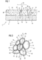
- FIG. 1 shows a layer structure 1, which consists of at least one Substrate 4 and an applied at least partially porous, at least partially gas-permeable Layer 7 exists.
- the substrate 4 is, for example, a turbine component, in particular a gas turbine 100 (FIG. 3) or a steam turbine, such as a support structure, a turbine blade 120, 130, a combustion liner 155 (FIGS. 4, 5), or another component that is cooled must become.
- the substrate 4 is made of, for example, a nickel- or cobalt-based superalloy.
- the materials of the substrate 4 and the layer 7 can be different or similar (metallic, ceramic) and / or similar, in particular if the intermediate layer 7 is produced together with the substrate 4.
- Intermediate layers e.g. an adhesive layer.
- the layer 7 is preferably metallic and consists for example, from a corrosion protection alloy of the type MCrAlX, where M is at least one element of the group iron (Fe), Cobalt (Co) or nickel (Ni) is.
- M is at least one element of the group iron (Fe), Cobalt (Co) or nickel (Ni) is.
- X stands for the element Yttrium (Y) and / or at least one element of the group of Rare Earth.
- the layer 7 may partially, ie limited to certain areas, have a lower or greater porosity.
- the layer 7 therefore has pores 10 in each case.
- the pores 10 are bounded by walls 37 (FIG. 2) and / or inlets / outlets of gas-permeable joints 20 (FIG. 2) in the layer 7.
- at least one coating 40 is applied to the walls 37 ( Figure 2) lining the walls inside.
- the porous layer 7 is, for example, foam or spongy with at least partially open, i. gas permeable pore structure formed.
- foam or sponge-like structure can, for example, by Applying a slurry to the substrate 4 made become.
- a heat treatment for example, by Gas formation bubbles, leaving a foamy structure arises, which connects simultaneously with the substrate 4.
- the substrate 4 has at least one cooling channel 16, through which a cooling medium, as indicated by the arrows, can flow.
- the porous layer 7 is made gas-permeable, so that the cooling medium from the cooling channel 16 in the layer 7 and then through the pores 10 and cooling channels 19 can flow.
- the layer 7 has at the surface 43, for example, points at which the cooling medium can escape from the layer 7.
- at least one cooling channel 19, in particular a cooling hole 19, ie without pores, can also be formed here.
- the cooling channels 19 can be introduced later.
- the cooling channels 19 are formed by gas-permeable connections between the pores 10 (FIG. 2).
- the layer 7 causes effusion cooling.
- the cooling channels 16, 19 are, for example, to each other arranged that a cooling medium as perpendicular to Surface of the substrate 4 or the layer 7 the Layer structure 1 flows through.
- the layer 7 does not necessarily have a film cooling exhibit. It can also be a closed circuit of a Cooling medium (gas, steam) should be present, so that no Cooling medium exiting the layer 7, but within the Layer 7, for example, along a flow direction 25 of a outside hot gas, flows.
- the layer 7 is then, for example, in the Area of the surface 43 is not gas-permeable, the area but below that again is gas permeable (not shown).
- intermediate walls 22 may also be present in the layer 7, which prevent the cooling medium within the intermediate layer 7 from flowing along the flow direction 25, because there is a pressure difference along the flow direction 25, as in a gas turbine 100, for example.
- the intermediate wall 22 may form individual chambers in the layer 7, as known from WO03 / 00688, which is intended to be part of this disclosure.
- the intermediate wall 22 may by separate, for example. Non-porous, Partitions or by non-permeable, but porous areas be formed of the layer 7 or by filling or welding the porous intermediate layer 7 in this Be made areas to dense partitions 22.
- the intermediate wall 22 is then e.g. an area that is not is gas permeable and thus a closed pore structure or no pores (non-porous).
- the size of the pores 10 is for example to the outside Surface 43 made smaller towards pollution to prevent the layer 7.
- the flow of a cooling medium can be adjusted in order to adapt it to a cooling capacity, which may be formed depending on location. This can also be adjusted by a location-dependent pore size in the intermediate layer 7.
- FIG. 2 shows an enlargement of the layer 7 of Figure 1, which is applied to the substrate 4.
- the layer 7 is a porous or foam-like metallic layer, as already described in FIG.
- the pores 10 are bounded by walls 37 and / or by the inlets / outlets of the gas-permeable connections 20 between the pores 10.
- the gas-permeable compounds 20 between the individual pores 10 and the pores 10 represent the cooling channels 19. As a rule, these are not rectilinear (shown schematically in a straight line in FIG. 1).
- the pore structure is formed so that a gas passage from the exit opening of the cooling channel 16 in the substrate 4 to the outer surface 43 of the layer 7 is possible.
- the coating 40 of the walls 37 of the porous layer 7 may extend over the entire thickness of the layer 7 as far as the substrate 4 or may be located only in a surface region 13 of the layer 7.
- the coating 40 is, for example, a ceramic layer, which can act in particular as a thermal barrier coating. This is, for example, alumina or yttrium-stabilized zirconia. In particular, ceramic coatings 40 can be used which do not require a bonding layer to the metallic intermediate layer 7.
- the outer coating 40 may be applied by dipping, slurry application, plasma spraying or other methods.
- the porous layer 7 may be prefabricated and is applied, for example, by soldering, gluing, welding or other fastening measures on the substrate 4, in particular directly.
- the porous layer 7 can also be produced, in particular cast, together with the substrate 4.
- the procedure may be as follows.
- the porous layer 7 is sprayed with a ceramic slurry or immersed in a corresponding liquid (immersion method), so that a greensheet is deposited on the walls 37 of the porous structure 7, which can still be compacted. This can be done by sintering or laser beam method.
- the layer system 1 can be used in newly manufactured components or can also be used for remanufactured components.
- components in particular turbine blades 120, 130 (FIG. 3) and combustor parts (FIGS. 4, 5), are refurbished after use (refurbishment) by removing the outer layers and further corrosion or oxidation layers.
- the component is checked for cracks, which are repaired if necessary. Thereafter, the component can again be provided with protective layers 7, 40 in order to form a layer system 1.
- FIG. 3 shows a gas turbine 100 in a partial longitudinal section.
- the gas turbine 100 has inside a rotatably mounted about a rotation axis 102 rotor 103, which is also referred to as a turbine runner.
- a compressor 105 for example, a toroidal combustion chamber 110, in particular annular combustion chamber 106, with a plurality of coaxially arranged burners 107, a turbine 108 and the exhaust housing 109th
- the annular combustion chamber 106 communicates with, for example, an annular hot gas channel 111.
- Each turbine stage 112 is formed of two blade rings.
- a series 125 formed of rotor blades 120 follows.
- the guide vanes 130 are in this case on an inner housing 138 a stator 143 attached, whereas the blades 120 a series 125, for example.
- a turbine disk 133 am Rotor 103 are mounted. Is coupled to the rotor 103 a generator or a work machine (not shown).
- air 105 is sucked in and compressed by the compressor 105 through the intake housing 104.
- the compressed air provided at the turbine-side end of the compressor 105 is supplied to the burners 107 where it is mixed with a fuel.
- the mixture is then burned to form the working fluid 113 in the combustion chamber 110.
- the working medium 113 flows along the hot gas channel 111 past the guide vanes 130 and the rotor blades 120.
- the working medium 113 expands in a pulse-transmitting manner, so that the rotor blades 120 drive the rotor 103 and drive the machine coupled to it.
- the components exposed to the hot working medium 113 are subject to thermal loads during operation of the gas turbine 100.
- the guide vanes 130 and rotor blades 120 of the first turbine stage 112, viewed in the direction of flow of the working medium 113, are subjected to the greatest thermal stress in addition to the heat shield bricks lining the annular combustion chamber 106.
- they are cooled by means of a coolant and have, for example, a layer 7 according to FIGS. 1, 2.
- the thermally heavily loaded components can be formed from substrates which have a directional structure, ie they are monocrystalline (SX structure) or have only longitudinal grains (DS structure).
- the material used is in particular iron-, nickel- or cobalt-based superalloys.
- the blades 120, 130 may be anti-corrosion coatings (MCrAlX; M is at least one element of the group iron (Fe), cobalt (Co), nickel (Ni), X is yttrium (Y) and / or at least one element of the rare Erden) and have heat through a thermal barrier coating.
- the thermal barrier coating consists for example of ZrO 2 , Y 2 O 4 -ZrO 2 , ie it is not, partially or completely stabilized by yttrium oxide and / or calcium oxide and / or magnesium oxide.
- suitable coating processes such as electron beam evaporation (EB-PVD), stalk-shaped grains are produced in the thermal barrier coating.
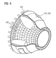
- FIG. 4 shows a combustion chamber 110 of a gas turbine 100.
- the combustion chamber 110 is configured, for example, as a so-called annular combustion chamber, in which a plurality of burners 102 arranged around the turbine shaft 103 in the circumferential direction open into a common combustion chamber space.
- the combustion chamber 110 is configured in its entirety as an annular structure, which is positioned around the turbine shaft 103 around.
- the combustion chamber 110 is designed for a comparatively high temperature of the working medium M of about 1000 ° C to 1600 ° C.
- the combustion chamber wall 153 is provided on its side facing the working medium M side with an inner lining formed from heat shield elements 155.
- Each heat shield element 155 is equipped on the working medium side with a particularly heat-resistant protective layer or made of high-temperature-resistant material. Due to the high temperatures in the interior of the combustion chamber 110, a cooling system is additionally provided for the heat shield elements 155 or for their holding elements.
- the heat shield elements 155 may have a layer structure 1 according to FIG. 1, 2.
- the materials of the combustion chamber wall and their coatings according to the present invention may be similar to Turbine blades 120, 130 be.
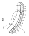
- FIG. 5 shows a heat shield arrangement 160, in which heat shield elements 155 are arranged on a supporting structure 163, one beside the other, covering the entire area.
- heat shield assembly 160 may, for example, line the combustor 110 and / or a transition region between combustor 110 and turbine blade 112 of a gas turbine engine 100 to prevent damage to the support structure 163 during operation of the gas turbine engine 100.
- the heat shield elements 155 each on the combustion chamber 110 facing away from the surface by means of Cooling cooling air.
- At least two adjacent heat shield elements 155a, 155b form between the support structure 163 and each of the Hot gas 113 facing away from surface of the heat shield elements 155a, 155b a cooling air duct 166. Communicate in this way the two mentioned adjacent heat shield elements 155a, 155b e.g. over the cooling air flow L, which directly from a the neighbors to the other in the by the neighbors formed, common cooling air channel 166 flows.
- the cooling air L which is fed through openings 169, 16 (FIG. 1) into the cooling air duct 166, cools the heat shield elements 155 at the rear, for example by means of impingement cooling, wherein the cooling air L strikes the surface of the heat shield elements 155, which faces away from the hot gas, virtually perpendicularly, and thereby thermal Can absorb and dissipate energy.
- the cooling of the heat shield elements 155 can continue to take place by convection cooling, wherein cooling air L thereby sweeps substantially parallel to the surface of the heat shield elements 155 at the rear along and thereby also absorb and dissipate thermal energy.
- the cooling air L as a cooling air flow largely moves from right to left in the cooling air passage 166 formed in common by the heat shield members 155, and can be supplied to a burner 107 provided in the combustion chamber 110, for example, to be used for combustion become.
- the heat shield elements 155 have, for example, an inventive layer structure 1 according to FIG. With the layer structure 1 can also be dispensed with the cooling channel 166 by a heat shield element 155 with the layer structure 1, for example, directly on the support structure 163, 4 is applied.
Landscapes
- Chemical & Material Sciences (AREA)
- Engineering & Computer Science (AREA)
- Mechanical Engineering (AREA)
- Materials Engineering (AREA)
- Inorganic Chemistry (AREA)
- Chemical Kinetics & Catalysis (AREA)
- Metallurgy (AREA)
- Organic Chemistry (AREA)
- General Engineering & Computer Science (AREA)
- Ceramic Engineering (AREA)
- Turbine Rotor Nozzle Sealing (AREA)
Priority Applications (8)
| Application Number | Priority Date | Filing Date | Title |
|---|---|---|---|
| EP20030015495 EP1496140A1 (fr) | 2003-07-09 | 2003-07-09 | Structure stratifiée et procédé pour sa production |
| EP20040763007 EP1641959B1 (fr) | 2003-07-09 | 2004-06-17 | Structure en couches et procede de realisation de structure en couches |
| PCT/EP2004/006556 WO2005005688A1 (fr) | 2003-07-09 | 2004-06-17 | Structure en couches et procede de realisation de structure en couches |
| PL04763007T PL1641959T3 (pl) | 2003-07-09 | 2004-06-17 | Struktura warstwowa i sposób wytwarzania struktury warstwowej |
| CNB2004800188937A CN100540743C (zh) | 2003-07-09 | 2004-06-17 | 层状结构和制造层状结构的方法 |
| US10/563,948 US7402335B2 (en) | 2003-07-09 | 2004-06-17 | Layer structure and method for producing such a layer structure |
| DE200450004097 DE502004004097D1 (de) | 2003-07-09 | 2004-06-17 | Schichtstruktur und verfahren zur herstellung einer schichtstruktur |
| ES04763007T ES2287758T3 (es) | 2003-07-09 | 2004-06-17 | Estructura en capas y procedimiento de produccion de una estructura en capas. |
Applications Claiming Priority (1)
| Application Number | Priority Date | Filing Date | Title |
|---|---|---|---|
| EP20030015495 EP1496140A1 (fr) | 2003-07-09 | 2003-07-09 | Structure stratifiée et procédé pour sa production |
Publications (1)
| Publication Number | Publication Date |
|---|---|
| EP1496140A1 true EP1496140A1 (fr) | 2005-01-12 |
Family
ID=33442767
Family Applications (2)
| Application Number | Title | Priority Date | Filing Date |
|---|---|---|---|
| EP20030015495 Withdrawn EP1496140A1 (fr) | 2003-07-09 | 2003-07-09 | Structure stratifiée et procédé pour sa production |
| EP20040763007 Expired - Lifetime EP1641959B1 (fr) | 2003-07-09 | 2004-06-17 | Structure en couches et procede de realisation de structure en couches |
Family Applications After (1)
| Application Number | Title | Priority Date | Filing Date |
|---|---|---|---|
| EP20040763007 Expired - Lifetime EP1641959B1 (fr) | 2003-07-09 | 2004-06-17 | Structure en couches et procede de realisation de structure en couches |
Country Status (7)
| Country | Link |
|---|---|
| US (1) | US7402335B2 (fr) |
| EP (2) | EP1496140A1 (fr) |
| CN (1) | CN100540743C (fr) |
| DE (1) | DE502004004097D1 (fr) |
| ES (1) | ES2287758T3 (fr) |
| PL (1) | PL1641959T3 (fr) |
| WO (1) | WO2005005688A1 (fr) |
Cited By (8)
| Publication number | Priority date | Publication date | Assignee | Title |
|---|---|---|---|---|
| EP2372103A1 (fr) * | 2007-12-04 | 2011-10-05 | Hitachi Ltd. | joint de turbine à vapeur |
| WO2010052095A3 (fr) * | 2008-11-07 | 2011-12-08 | Deutsches Zentrum für Luft- und Raumfahrt e.V. | Structure de protection et utilisation |
| EP2725120A1 (fr) * | 2012-10-24 | 2014-04-30 | Hitachi Ltd. | Composants à haute température avec des revêtements de barrière thermique pour turbine à gaz |
| EP2845918A1 (fr) * | 2013-09-04 | 2015-03-11 | Siemens Aktiengesellschaft | Procédé destiné à revêtir au moins partiellement une aube, dispositif de revêtement et aube |
| EP3244013A1 (fr) * | 2016-05-12 | 2017-11-15 | General Electric Company | Élément refroidi à peau poreuse |
| EP3255172A1 (fr) * | 2016-05-27 | 2017-12-13 | General Electric Company | Article de dissipation thermique et procédé de formation d'un article de dissipation thermique |
| EP3323996A1 (fr) * | 2016-11-17 | 2018-05-23 | United Technologies Corporation | Composant de moteur à turbine avec section de revêtement segmenté géométriquement et passage de refroidissement |
| US10393177B2 (en) | 2015-07-21 | 2019-08-27 | Deutsches Zentrum Fuer Luft-Und Raumfahrt E.V. | Sliding bearing device |
Families Citing this family (31)
| Publication number | Priority date | Publication date | Assignee | Title |
|---|---|---|---|---|
| EP1533113A1 (fr) * | 2003-11-14 | 2005-05-25 | Siemens Aktiengesellschaft | Système stratifié pour dissipation de chaleur à haute température et méthode de fabrication |
| US7704049B1 (en) * | 2006-12-08 | 2010-04-27 | Florida Turbine Technologies, Inc. | TBC attachment construction for a cooled turbine airfoil and method of forming a TBC covered airfoil |
| CN101078354B (zh) * | 2007-06-06 | 2013-03-27 | 北京航空航天大学 | 多孔金属叶片耦合设计方法 |
| US20120067054A1 (en) | 2010-09-21 | 2012-03-22 | Palmer Labs, Llc | High efficiency power production methods, assemblies, and systems |
| US8739404B2 (en) | 2010-11-23 | 2014-06-03 | General Electric Company | Turbine components with cooling features and methods of manufacturing the same |
| US20120156054A1 (en) * | 2010-12-15 | 2012-06-21 | General Electric Company | Turbine component with near-surface cooling passage and process therefor |
| US8793871B2 (en) | 2011-03-17 | 2014-08-05 | Siemens Energy, Inc. | Process for making a wall with a porous element for component cooling |
| US20130086784A1 (en) * | 2011-10-06 | 2013-04-11 | General Electric Company | Repair methods for cooled components |
| CH706090A1 (de) | 2012-02-17 | 2013-08-30 | Alstom Technology Ltd | Verfahren zum Herstellen eines oberflächennahen Kühlkanals in einem thermisch hoch beanspruchten Bauteil sowie Bauteil mit einem solchen Kanal. |
| WO2013144022A1 (fr) | 2012-03-28 | 2013-10-03 | Alstom Technology Ltd | Procédé pour retirer une céramique |
| US9493228B2 (en) | 2012-11-28 | 2016-11-15 | The Boeing Company | High heat transfer rate reusable thermal protection system |
| US10018052B2 (en) | 2012-12-28 | 2018-07-10 | United Technologies Corporation | Gas turbine engine component having engineered vascular structure |
| WO2014105108A1 (fr) | 2012-12-28 | 2014-07-03 | United Technologies Corporation | Composant de moteur à turbine à gaz à structure maillée vasculaire artificielle |
| EP2988881A4 (fr) * | 2013-02-15 | 2016-07-20 | Virginia Tech Intell Prop | Fabrication de revêtements métalliques poreux par dépôt électrolytique et compositions de ces derniers |
| US10100666B2 (en) * | 2013-03-29 | 2018-10-16 | General Electric Company | Hot gas path component for turbine system |
| EP3060695B1 (fr) * | 2013-10-21 | 2019-12-11 | United Technologies Corporation | Conception de fixation en céramique et procédé de fabrication |
| EP2884048A1 (fr) * | 2013-12-13 | 2015-06-17 | Siemens Aktiengesellschaft | Revêtement d'isolation thermique d'une aube de turbine |
| GB201403404D0 (en) | 2014-02-27 | 2014-04-16 | Rolls Royce Plc | A combustion chamber wall and a method of manufacturing a combustion chamber wall |
| US9718735B2 (en) * | 2015-02-03 | 2017-08-01 | General Electric Company | CMC turbine components and methods of forming CMC turbine components |
| US10094287B2 (en) | 2015-02-10 | 2018-10-09 | United Technologies Corporation | Gas turbine engine component with vascular cooling scheme |
| US10458653B2 (en) * | 2015-06-05 | 2019-10-29 | Rolls-Royce Corporation | Machinable CMC insert |
| US10465534B2 (en) * | 2015-06-05 | 2019-11-05 | Rolls-Royce North American Technologies, Inc. | Machinable CMC insert |
| US10472976B2 (en) * | 2015-06-05 | 2019-11-12 | Rolls-Royce Corporation | Machinable CMC insert |
| US10221694B2 (en) | 2016-02-17 | 2019-03-05 | United Technologies Corporation | Gas turbine engine component having vascular engineered lattice structure |
| US10508551B2 (en) * | 2016-08-16 | 2019-12-17 | General Electric Company | Engine component with porous trench |
| US10662779B2 (en) * | 2016-11-17 | 2020-05-26 | Raytheon Technologies Corporation | Gas turbine engine component with degradation cooling scheme |
| US10400608B2 (en) * | 2016-11-23 | 2019-09-03 | General Electric Company | Cooling structure for a turbine component |
| WO2018144064A1 (fr) * | 2017-02-03 | 2018-08-09 | Siemens Aktiengesellschaft | Panneau refroidi par air pour turbine, à treillis tridimensionnel monolithique, et son procédé de fabrication |
| US10774653B2 (en) | 2018-12-11 | 2020-09-15 | Raytheon Technologies Corporation | Composite gas turbine engine component with lattice structure |
| DE102019204746A1 (de) * | 2019-04-03 | 2020-10-08 | Siemens Aktiengesellschaft | Hitzeschildkachel mit Dämpfungsfunktion |
| US11702992B2 (en) * | 2021-12-03 | 2023-07-18 | Raytheon Company | Combustor wall core with resonator and/or damper elements |
Citations (4)
| Publication number | Priority date | Publication date | Assignee | Title |
|---|---|---|---|---|
| EP0609795A1 (fr) * | 1993-02-04 | 1994-08-10 | Mtu Motoren- Und Turbinen-Union MàNchen Gmbh | Couche d'isolation thermique céramique sur éléments métalliques et procédé de manufacture |
| EP0852223A1 (fr) * | 1996-12-04 | 1998-07-08 | European Atomic Energy Community (Euratom) | Procédé pour boucher des revêtements poreux, en particulier des barrières thermiques |
| US6428280B1 (en) * | 2000-11-08 | 2002-08-06 | General Electric Company | Structure with ceramic foam thermal barrier coating, and its preparation |
| US20030021905A1 (en) * | 2000-11-06 | 2003-01-30 | Ching-Pang Lee | Method for cooling engine components using multi-layer barrier coating |
Family Cites Families (10)
| Publication number | Priority date | Publication date | Assignee | Title |
|---|---|---|---|---|
| US3825364A (en) | 1972-06-09 | 1974-07-23 | Gen Electric | Porous abradable turbine shroud |
| GB2053367B (en) | 1979-07-12 | 1983-01-26 | Rolls Royce | Cooled shroud for a gas turbine engine |
| US4761654A (en) | 1985-06-25 | 1988-08-02 | Communications Satellite Corporation | Electromagnetically coupled microstrip antennas having feeding patches capacitively coupled to feedlines |
| US5080557A (en) | 1991-01-14 | 1992-01-14 | General Motors Corporation | Turbine blade shroud assembly |
| JPH10231704A (ja) | 1997-02-18 | 1998-09-02 | Ishikawajima Harima Heavy Ind Co Ltd | しみ出し冷却タービンシュラウド |
| US6306424B1 (en) * | 1999-06-30 | 2001-10-23 | Ethicon, Inc. | Foam composite for the repair or regeneration of tissue |
| DE10024302A1 (de) * | 2000-05-17 | 2001-11-22 | Alstom Power Nv | Verfahren zur Herstellung eines thermisch belasteten Gussteils |
| GB0117110D0 (en) | 2001-07-13 | 2001-09-05 | Siemens Ag | Coolable segment for a turbomachinery and combustion turbine |
| EP1327703A1 (fr) * | 2002-01-15 | 2003-07-16 | Siemens Aktiengesellschaft | Système de revêtement avec une couche poreuse |
| EP1533113A1 (fr) * | 2003-11-14 | 2005-05-25 | Siemens Aktiengesellschaft | Système stratifié pour dissipation de chaleur à haute température et méthode de fabrication |
-
2003
- 2003-07-09 EP EP20030015495 patent/EP1496140A1/fr not_active Withdrawn
-
2004
- 2004-06-17 PL PL04763007T patent/PL1641959T3/pl unknown
- 2004-06-17 CN CNB2004800188937A patent/CN100540743C/zh not_active Expired - Fee Related
- 2004-06-17 EP EP20040763007 patent/EP1641959B1/fr not_active Expired - Lifetime
- 2004-06-17 WO PCT/EP2004/006556 patent/WO2005005688A1/fr not_active Ceased
- 2004-06-17 ES ES04763007T patent/ES2287758T3/es not_active Expired - Lifetime
- 2004-06-17 DE DE200450004097 patent/DE502004004097D1/de not_active Expired - Lifetime
- 2004-06-17 US US10/563,948 patent/US7402335B2/en not_active Expired - Fee Related
Patent Citations (4)
| Publication number | Priority date | Publication date | Assignee | Title |
|---|---|---|---|---|
| EP0609795A1 (fr) * | 1993-02-04 | 1994-08-10 | Mtu Motoren- Und Turbinen-Union MàNchen Gmbh | Couche d'isolation thermique céramique sur éléments métalliques et procédé de manufacture |
| EP0852223A1 (fr) * | 1996-12-04 | 1998-07-08 | European Atomic Energy Community (Euratom) | Procédé pour boucher des revêtements poreux, en particulier des barrières thermiques |
| US20030021905A1 (en) * | 2000-11-06 | 2003-01-30 | Ching-Pang Lee | Method for cooling engine components using multi-layer barrier coating |
| US6428280B1 (en) * | 2000-11-08 | 2002-08-06 | General Electric Company | Structure with ceramic foam thermal barrier coating, and its preparation |
Non-Patent Citations (1)
| Title |
|---|
| XOMERITAKIS G ET AL: "Fabrication of a thin palladium membrane supported in a porous ceramic substrate by chemical vapor deposition", JOURNAL OF MEMBRANE SCIENCE, ELSEVIER SCIENTIFIC PUBL.COMPANY. AMSTERDAM, NL, vol. 120, no. 2, 13 November 1996 (1996-11-13), pages 261 - 272, XP004041862, ISSN: 0376-7388 * |
Cited By (13)
| Publication number | Priority date | Publication date | Assignee | Title |
|---|---|---|---|---|
| US8128351B2 (en) | 2007-12-04 | 2012-03-06 | Hitachi, Ltd. | Seals in steam turbine |
| US8500397B2 (en) | 2007-12-04 | 2013-08-06 | Hitachi, Ltd. | Seals in steam turbine |
| EP2372103A1 (fr) * | 2007-12-04 | 2011-10-05 | Hitachi Ltd. | joint de turbine à vapeur |
| WO2010052095A3 (fr) * | 2008-11-07 | 2011-12-08 | Deutsches Zentrum für Luft- und Raumfahrt e.V. | Structure de protection et utilisation |
| EP2725120A1 (fr) * | 2012-10-24 | 2014-04-30 | Hitachi Ltd. | Composants à haute température avec des revêtements de barrière thermique pour turbine à gaz |
| EP2845918A1 (fr) * | 2013-09-04 | 2015-03-11 | Siemens Aktiengesellschaft | Procédé destiné à revêtir au moins partiellement une aube, dispositif de revêtement et aube |
| US10393177B2 (en) | 2015-07-21 | 2019-08-27 | Deutsches Zentrum Fuer Luft-Und Raumfahrt E.V. | Sliding bearing device |
| EP3244013A1 (fr) * | 2016-05-12 | 2017-11-15 | General Electric Company | Élément refroidi à peau poreuse |
| CN107448244A (zh) * | 2016-05-12 | 2017-12-08 | 通用电气公司 | 具有多孔表皮的冷却的部件 |
| EP3255172A1 (fr) * | 2016-05-27 | 2017-12-13 | General Electric Company | Article de dissipation thermique et procédé de formation d'un article de dissipation thermique |
| US10145000B2 (en) | 2016-05-27 | 2018-12-04 | General Electric Company | Thermally dissipative article and method of forming a thermally dissipative article |
| EP3323996A1 (fr) * | 2016-11-17 | 2018-05-23 | United Technologies Corporation | Composant de moteur à turbine avec section de revêtement segmenté géométriquement et passage de refroidissement |
| US10309238B2 (en) | 2016-11-17 | 2019-06-04 | United Technologies Corporation | Turbine engine component with geometrically segmented coating section and cooling passage |
Also Published As
| Publication number | Publication date |
|---|---|
| PL1641959T3 (pl) | 2007-10-31 |
| US20060153685A1 (en) | 2006-07-13 |
| EP1641959A1 (fr) | 2006-04-05 |
| CN1816646A (zh) | 2006-08-09 |
| DE502004004097D1 (de) | 2007-07-26 |
| WO2005005688A1 (fr) | 2005-01-20 |
| ES2287758T3 (es) | 2007-12-16 |
| CN100540743C (zh) | 2009-09-16 |
| US7402335B2 (en) | 2008-07-22 |
| EP1641959B1 (fr) | 2007-06-13 |
Similar Documents
| Publication | Publication Date | Title |
|---|---|---|
| EP1641959B1 (fr) | Structure en couches et procede de realisation de structure en couches | |
| EP1682342B1 (fr) | Systeme stratifie pour dissipation de chaleur a haute temperature et methode de fabrication | |
| DE60216177T2 (de) | Kühlsystem einer beschichteten Turbinenschaufelspitze | |
| CH703549A2 (de) | Brennkammerflammrohr mit Kühlsystem. | |
| WO2012062546A1 (fr) | Système à couches poreux, muni d'une couche interne poreuse | |
| EP2216509A1 (fr) | Composant de turbine doté d'une couche de protection pouvant être enlevée simplement, ensemble de composants de turbines, turbine et procédé de protection d'un composant de turbine | |
| EP2373824A1 (fr) | Procédé pour recouvrir un composant pourvu de trous de refroidissement pelliculaire et composant | |
| WO2009065753A1 (fr) | Procédé de brasage de fissures larges | |
| EP2230041A2 (fr) | Procédé de fabrication d'un trou | |
| EP2391744A2 (fr) | Enduction par des procédés d'enduction thermiques et non thermiques | |
| WO2009087189A2 (fr) | Brasage de trous, procédé de revêtement et baguettes de brasure | |
| EP1462613A1 (fr) | Revêtement refroidissable | |
| EP2138258A1 (fr) | Procédé de soudage à profil de température à plusieurs niveaux | |
| EP1816316B1 (fr) | Procédé de réparation de composants | |
| WO2008107293A1 (fr) | Procédé pour appliquer un revêtement calorifuge, et éléments de turbine pourvus d'un revêtement calorifuge | |
| EP1820939A1 (fr) | Procédé et dispositiv pour le revêtement des aubes de turbine | |
| EP1806430A1 (fr) | Revêmtement céramique ayant une haute porositée, utilisation de celle-ci revêtement et composant comprenant telle revêtement | |
| EP1772529A1 (fr) | Composition chimique sèche, utilisation de celle-ci composition pour fabriquer un revêtement multicouche et méthode pour fabriquer ce revêtement | |
| WO2011057661A1 (fr) | Composant comportant des zones de ductilité différente et procédé de fabrication d'un composant | |
| EP1811055A1 (fr) | Methode pour fabriquer un composant avec des orifices | |
| EP2082076A1 (fr) | Procédé d'optimisation de revêtement par un coupon et composant avec coupon | |
| WO2012065851A1 (fr) | Procédé raccourci pour le forage d'un trou | |
| EP2102379A1 (fr) | Procédé de fabrication d'une aube de turbine qui présente un oxyde sur une couche métallique, utilisation de cette aube de turbine, turbine et procédé d'utilisation d'une turbine | |
| WO2007051752A1 (fr) | Composition seche, son utilisation, systeme stratifie et procede d’enduction | |
| EP2340137A1 (fr) | Pièce moulée à module séparé pour entretoise, procédé de production d'un moule de coulée, moule de coulée céramique et pièce moulée |
Legal Events
| Date | Code | Title | Description |
|---|---|---|---|
| PUAI | Public reference made under article 153(3) epc to a published international application that has entered the european phase |
Free format text: ORIGINAL CODE: 0009012 |
|
| AK | Designated contracting states |
Kind code of ref document: A1 Designated state(s): AT BE BG CH CY CZ DE DK EE ES FI FR GB GR HU IE IT LI LU MC NL PT RO SE SI SK TR |
|
| AX | Request for extension of the european patent |
Extension state: AL LT LV MK |
|
| AKX | Designation fees paid | ||
| REG | Reference to a national code |
Ref country code: DE Ref legal event code: 8566 |
|
| STAA | Information on the status of an ep patent application or granted ep patent |
Free format text: STATUS: THE APPLICATION IS DEEMED TO BE WITHDRAWN |
|
| 18D | Application deemed to be withdrawn |
Effective date: 20050713 |