EP1496169B1 - Herstellungsverfahren für ein Dach mit Hohlziegeln und solch ein Dach - Google Patents
Herstellungsverfahren für ein Dach mit Hohlziegeln und solch ein Dach Download PDFInfo
- Publication number
- EP1496169B1 EP1496169B1 EP04358006A EP04358006A EP1496169B1 EP 1496169 B1 EP1496169 B1 EP 1496169B1 EP 04358006 A EP04358006 A EP 04358006A EP 04358006 A EP04358006 A EP 04358006A EP 1496169 B1 EP1496169 B1 EP 1496169B1
- Authority
- EP
- European Patent Office
- Prior art keywords
- tiles
- corrugations
- tile
- ridges
- polyurethane foam
- Prior art date
- Legal status (The legal status is an assumption and is not a legal conclusion. Google has not performed a legal analysis and makes no representation as to the accuracy of the status listed.)
- Expired - Lifetime
Links
- 238000000034 method Methods 0.000 title claims description 30
- 238000004519 manufacturing process Methods 0.000 title claims description 5
- 239000000463 material Substances 0.000 claims description 33
- 229920005830 Polyurethane Foam Polymers 0.000 claims description 20
- 239000011496 polyurethane foam Substances 0.000 claims description 20
- 230000002787 reinforcement Effects 0.000 claims description 6
- 125000006850 spacer group Chemical group 0.000 claims description 6
- 229920002635 polyurethane Polymers 0.000 claims description 5
- 239000004814 polyurethane Substances 0.000 claims description 5
- 239000004793 Polystyrene Substances 0.000 claims description 3
- 230000001788 irregular Effects 0.000 claims description 3
- 229920002223 polystyrene Polymers 0.000 claims description 3
- 229920002994 synthetic fiber Polymers 0.000 claims description 2
- 239000011324 bead Substances 0.000 description 10
- 239000002184 metal Substances 0.000 description 9
- 239000004570 mortar (masonry) Substances 0.000 description 9
- 239000006260 foam Substances 0.000 description 6
- XLYOFNOQVPJJNP-UHFFFAOYSA-N water Substances O XLYOFNOQVPJJNP-UHFFFAOYSA-N 0.000 description 5
- 229910000831 Steel Inorganic materials 0.000 description 4
- 239000004568 cement Substances 0.000 description 4
- 238000010276 construction Methods 0.000 description 4
- 239000010959 steel Substances 0.000 description 4
- 238000005452 bending Methods 0.000 description 3
- 238000009434 installation Methods 0.000 description 3
- 241000195940 Bryophyta Species 0.000 description 2
- 241000422252 Cales Species 0.000 description 2
- 241000826860 Trapezium Species 0.000 description 2
- 239000000443 aerosol Substances 0.000 description 2
- 238000000151 deposition Methods 0.000 description 2
- 238000001125 extrusion Methods 0.000 description 2
- 238000011065 in-situ storage Methods 0.000 description 2
- 235000011929 mousse Nutrition 0.000 description 2
- 239000003380 propellant Substances 0.000 description 2
- 239000000565 sealant Substances 0.000 description 2
- 229910001335 Galvanized steel Inorganic materials 0.000 description 1
- 229920001730 Moisture cure polyurethane Polymers 0.000 description 1
- 230000032683 aging Effects 0.000 description 1
- 238000005097 cold rolling Methods 0.000 description 1
- 239000000470 constituent Substances 0.000 description 1
- 230000032798 delamination Effects 0.000 description 1
- 230000008021 deposition Effects 0.000 description 1
- 238000001035 drying Methods 0.000 description 1
- 230000000694 effects Effects 0.000 description 1
- 229920001971 elastomer Polymers 0.000 description 1
- 239000000806 elastomer Substances 0.000 description 1
- 239000000835 fiber Substances 0.000 description 1
- 239000011152 fibreglass Substances 0.000 description 1
- 230000008014 freezing Effects 0.000 description 1
- 238000007710 freezing Methods 0.000 description 1
- 239000008397 galvanized steel Substances 0.000 description 1
- 238000002347 injection Methods 0.000 description 1
- 239000007924 injection Substances 0.000 description 1
- 238000001746 injection moulding Methods 0.000 description 1
- 238000009413 insulation Methods 0.000 description 1
- 238000012423 maintenance Methods 0.000 description 1
- 239000013521 mastic Substances 0.000 description 1
- 238000006116 polymerization reaction Methods 0.000 description 1
- 239000004588 polyurethane sealant Substances 0.000 description 1
- 230000003014 reinforcing effect Effects 0.000 description 1
- 230000003252 repetitive effect Effects 0.000 description 1
- 229920005989 resin Polymers 0.000 description 1
- 239000011347 resin Substances 0.000 description 1
- 238000005096 rolling process Methods 0.000 description 1
- 238000007789 sealing Methods 0.000 description 1
- 238000007493 shaping process Methods 0.000 description 1
- 239000007787 solid Substances 0.000 description 1
- 230000035882 stress Effects 0.000 description 1
- 239000011800 void material Substances 0.000 description 1
Images


Classifications
-
- E—FIXED CONSTRUCTIONS
- E04—BUILDING
- E04B—GENERAL BUILDING CONSTRUCTIONS; WALLS, e.g. PARTITIONS; ROOFS; FLOORS; CEILINGS; INSULATION OR OTHER PROTECTION OF BUILDINGS
- E04B7/00—Roofs; Roof construction with regard to insulation
- E04B7/20—Roofs consisting of self-supporting slabs, e.g. able to be loaded
- E04B7/205—Roofs consisting of self-supporting slabs, e.g. able to be loaded the slabs having non-structural supports for roofing materials
-
- E—FIXED CONSTRUCTIONS
- E04—BUILDING
- E04D—ROOF COVERINGS; SKY-LIGHTS; GUTTERS; ROOF-WORKING TOOLS
- E04D1/00—Roof covering by making use of tiles, slates, shingles, or other small roofing elements
- E04D1/29—Means for connecting or fastening adjacent roofing elements
-
- E—FIXED CONSTRUCTIONS
- E04—BUILDING
- E04D—ROOF COVERINGS; SKY-LIGHTS; GUTTERS; ROOF-WORKING TOOLS
- E04D1/00—Roof covering by making use of tiles, slates, shingles, or other small roofing elements
- E04D1/29—Means for connecting or fastening adjacent roofing elements
- E04D1/2907—Means for connecting or fastening adjacent roofing elements by interfitted sections
- E04D1/2914—Means for connecting or fastening adjacent roofing elements by interfitted sections having fastening means or anchors at juncture of adjacent roofing elements
- E04D1/2916—Means for connecting or fastening adjacent roofing elements by interfitted sections having fastening means or anchors at juncture of adjacent roofing elements the fastening means taking hold directly on adjacent elements of the same row
-
- E—FIXED CONSTRUCTIONS
- E04—BUILDING
- E04D—ROOF COVERINGS; SKY-LIGHTS; GUTTERS; ROOF-WORKING TOOLS
- E04D1/00—Roof covering by making use of tiles, slates, shingles, or other small roofing elements
- E04D1/34—Fastenings for attaching roof-covering elements to the supporting elements
-
- E—FIXED CONSTRUCTIONS
- E04—BUILDING
- E04D—ROOF COVERINGS; SKY-LIGHTS; GUTTERS; ROOF-WORKING TOOLS
- E04D1/00—Roof covering by making use of tiles, slates, shingles, or other small roofing elements
- E04D1/34—Fastenings for attaching roof-covering elements to the supporting elements
- E04D2001/3452—Fastenings for attaching roof-covering elements to the supporting elements characterised by the location of the fastening means
- E04D2001/3455—Fastenings for attaching roof-covering elements to the supporting elements characterised by the location of the fastening means on the internal surface of the roof covering elements
-
- E—FIXED CONSTRUCTIONS
- E04—BUILDING
- E04D—ROOF COVERINGS; SKY-LIGHTS; GUTTERS; ROOF-WORKING TOOLS
- E04D1/00—Roof covering by making use of tiles, slates, shingles, or other small roofing elements
- E04D1/34—Fastenings for attaching roof-covering elements to the supporting elements
- E04D2001/3488—Fastenings for attaching roof-covering elements to the supporting elements characterised by the type of roof covering elements being fastened
- E04D2001/3497—Spanish type tiles
Definitions
- the present invention relates to a method of building round tile roofs on self-supporting bins and a roof obtained.
- the technical field of the invention is that of the construction of roof tiles channel or round tiles of cylindro-conical shape.
- FR 2 541 709 describes a method which makes it possible to provide new roofs in round tiles, which make it possible to preserve the architectural aspect of the traditional roof, process in which the round tiles are placed on a sub-roof which presents a good water and airtightness, which is easy to install and reduces the cost of the roof.
- This process involves the implementation of self-supporting metal bins, usually galvanized or oven-lacquered sheet bins, which are used to build roofs of industrial buildings or side siding.
- the self-supporting laminated sheet or laminated resin bins have, thanks to their ribbed ribbed form, a very good resistance to bending, so that the purlins that support them can be spaced apart.
- This crenellated profile makes it possible to stiffen the tray and thus to reduced thicknesses and thus lighter bins compared to a profile tray with fluted corrugations, that is to say of round shape.
- roofs of this type is very fast and does not require a highly qualified workforce and this method of building roofs reduces the time and cost of building round tile roofs.
- This method makes it possible to obtain a good mechanical connection between the tiles and the self-supporting bins thanks to the presence of an armature formed of an expanded metal strip or metal mesh extending over the entire length of the bins, which is fixed anchor bolts on the purlins.
- These self-supporting tanks can be manufactured by hand by cold rolling or bending galvanized steel sheet or kiln-lacquered, standard width.
- roofs of this type compared to round tile roofs laid on corrugated fiber cement sheets, are that they make it possible to build roofs with lower slopes thanks to better watertightness and thanks to the form hollow grooves that allow better water flow.
- a disadvantage is that the tiles, whose round concave shape is not supported by the slots whose vertices are flat, must be supported by a spacer material or device adhering to the tray and supporting the tiles.
- the implementation of a lattice reinforcement which allows the adhesion of the mortar on the self-supporting tray, represents an additional laying work as well as an additional weight load.
- the mortar also has some disadvantage. Firstly, its weight is relatively high, a material with a density of more than 1000 kg / m 3 and, in practice for roofing, a surface density greater than 25 kg / m 2 . In addition, the mortar reacts differently from the constituent material of the tile as a function of the ambient temperature, generating different dimensional variations that can induce delamination of the tile, or even the breaking of tiles. Finally, the mortar does not confer steady underside of the tile because, when the mortar dries, it retracts in a non-homogeneous manner, which generates mini void areas under the tile which are as many points of failure of sound insulation but also of risk of detachment or fragility of the tile.
- US 6,164,021 A discloses a method of making roofs wherein the corner and ridge tiles are fixed by injection of expanded polyurethane foam under the tiles to fill the voids and seal.
- the document FR 2,619,688 describes a method for producing a traditional roof in which concavity-channel tiles are alternately raised upwards and downwards, trapezoidal chevrons making it possible to hold and wedge the tiles placed concavity upwards.
- the purpose of the present invention is therefore to provide a method of producing round tile roofs placed on a steel bucket profile slot that does not have the disadvantages of the method of the prior art, in particular described in FR 2 541 709, in particular with means for supporting and adhering the tiles on said self-supporting bins which do not have the disadvantages of the implementation of a metal mesh reinforcement combined with a mortar for the adhesion and support of the tiles on said tray.
- the present invention provides a method for producing a roof tile channel as defined by claim 1 wherein said tiles are placed on supports comprising self-supporting ribbed trays, corrugated crenel, with son of said sloping tiles on the tops of said battlements, and said row tiles overlapping so that the lower end of each tile covers the upper end of the tile located immediately lower in the slope, said tiles having all one Concavity directed downwards.
- the present invention offers several advantages.
- the means of connection between the tiles and the steel tanks constitutes a continuous bearing surface on the underside of the tile and this, both in the case of tiles with the formerly of irregular non-repetitive shapes for which it will then be advantageously used a said expanded polyurethane foam material in situ, than in the case of industrial tiles of identical regular shapes for which it will then be possible to use both preformed wedges that shims of expanded polyurethane foam in situ.
- said preformed wedges are made of polystyrene or polyurethane.
- said material, consisting of said polyurethane foam or said preformed wedges has a density of 35 to 55 kg / m 3 .
- said material consisting of said expanded polyurethane foam or said preformed wedges occupies the volume formed between said tiles and said peaks of said crenellations so that said peaks of said crenellations are substantially at a height corresponding substantially to half the depth of said tiles.
- the inventors have, in fact, discovered that the amount of said material and in particular expanded polyurethane foam thus set The work is sufficient to provide both adhesion and reliable mechanical support for the tiles on the self-supporting tray.
- the weight of said material depending on the nature of the material may be from 10 g / m 2 to 10 kg / m 2 , more particularly from 5 g / m 2 to 1000 g / m 2 .
- the weight will generally be 5 to 10 kg / m 2
- this weight will generally be 100 to 1000 g / m 2
- the weight of the material will be more particularly from 20 to 500 g / m 2 .
- a laying of about 10 tiles per m 2 is carried out , said tiles overlapping in each line over a length of 5 to 10 cm.
- Said peaks of said crenellations comprise two longitudinal grooves, each of said two grooves being disposed along the lateral edges of said crenellations and thus delimiting the width of the zone initially covered by the expanded polyurethane foam at the moment of its deposition on said vertices of said crenellations in the form of of polyurethane foam cords.
- said tiles are glued to each other at their ends at said overlap area without fixing hook.
- said tiles are tiles of identical regular shape and said material is constituted by said preformed wedges.
- said tiles are irregularly shaped and non-identical tiles and said material is made of said expanded polyurethane foam.
- said peaks of said crenellations have a width of 110 to 115 mm, said crenellations having a height of the order of 50 mm and the sidewall of said trapezoidal crenels diverging upwardly at an angle of between 0 and 15 mm. °.
- These self-supporting tanks are made of sheet metal 0.5 to 1 mm thick and have a weight of the order of 4 to 10 kg / m 2 which is a relatively low weight compared to that of other known sub-roofs, this which allows to lighten the frame.
- the present invention also relates to a roof of the type comprising round tiles, obtained by a method according to the invention, characterized in that it comprises, interposed between said tiles and said tray, a said material as defined above .
- the present invention aims to facilitate the construction of roofs of individual houses but it is not limited to this application and roofs according to the present invention can be used to cover other buildings, including collective housing or industrial premises.
- the roof according to the present invention results from the laying of frustoconical tiles 1 on a tray 2 of preformed steel, a material 3, 4 ensuring the maintenance of the tile 1 on the tray 2.
- Figure 1 shows a first embodiment
- the tray 2 is obtained from a steel sheet, initially flat, whose thickness is of the order of 0.63 mm and whose weight is of the order of 7.6 kg / m 2 .
- Trapezoidal crenellations 22 are formed in the width of this sheet, for example by rolling.
- crenellations 22 are formed by a succession of surfaces 212 forming the small upper base of the vertices 21, said surfaces 212 being framed by two lateral sides inclined to the convergent blank 211 and 214.
- the sheet thus formed advantageously has a variable length, at most 1200 mm, a useful width of 660 mm and a crest height of 50 mm.
- a peak 21 forms a convex trapezium the length of the small upper base 212 is about 113 mm.
- the two inclined sides 211, 214 of each concave slit 22 or convex trapezium 21 are respectively divergent or convergent upwards with a draft relief angle of between 0 and 15 °.
- These tanks are supported by unrepresented structural elements that may be metal or timber or prefabricated concrete frameworks. They are for example fixed on not-represented battens by bolts or lag bolts, or threaded rods, or any other equivalent fastener, which pass through fixing holes advantageously drilled through the small base 212 of the vertices 21, in contact with the tiles, the small base 221 concave slots 22 being in contact with the battens.
- a first tray installed, it is positioned in the same way just next to it a second tray.
- the two edges in contact each have a crenel portion, made so that the slot portion at the edge of the second tray partially overlaps at least the slot portion at the edge of the first tray.
- Useful width previously mentioned is the width of a tray 2 which is not covered by the bins fixed on either side thereof.
- Each tray advantageously has at each of its ends a crown portion 21, made so that the crown portion 21 of a second tank which covers the crown portion 21 of a first tank located next to it, has a a small solid base 212 and a side portion 211 extending over at least one-third of the length of the entire 211 side of the top portion 21 of the first bin.
- the latter also has a portion of small base 212 which extends under at least half the length of the small base 212 complete the second tray.
- This type of assembly ensures the tightness of the device, rain water flows on the side portion 211 of the upper tray and falls on the full 211 side of the lower tray.
- each plate has two vertices 21 full and three concave slots 22 full.
- Each small base 212 of each vertex 21 has two grooves in "V" 213. These grooves are made during the shaping of the sheet.
- This type of tile is standard and commonly used by those skilled in the art. They can be regular or irregular and generally have a length of 40 or 50 cm, a small width of about 17 cm and a large width of about 21 cm.
- the lower part of a gutter tile 1 that is to say the part situated on the side of the large width covers the upper part, that is to say the part situated on the side of the small width of the tile arranged immediately after.
- the cover is then at least 60 mm.
- two tiles are secured together by two studs 5 of about 0.5 cm 3 of mastic made in the overlap area.
- One-component polyurethane-based elastomer sealant is preferably used.
- This type of putty proposed in particular by the company SIKA under the trade name SIKAFLEX 11FC or FIXOTUILE, is packaged in a cartridge and its installation is done by manual or pneumatic gun.
- This type of sealant cures under the action of moisture and wind and has excellent resistance to aging and weathering.
- the present invention proposes to interpose between each tile 1 and the tray 2 a material 3, 4.
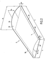
- This material may be a wedge 3 as shown in FIGS. 1 and 2, or a bead of foam 4 as represented in FIG.
- a shim 3 it is obtained by injection molding of a material which can be composed essentially of polystyrene or polyurethane and having a density of 25 to 40 kg / m 3 .
- a wedge 3 has a flat bottom face 32, trapezoidal shape, and a convex upper surface 31, frustoconical.
- This wedge advantageously has a length L of 150 to 250 mm, a small width I 1 of 60 to 110 mm, a large width I 2 of 80 to 120 mm, a small height h 1 of 15 to 30 mm and a large height h 2 from 20 to 45 mm.
- a shim 3 is then inserted between each tile 1 and the tray 2, the flat bottom face 32 is then in contact on the tray 2, the convex upper face 31 then cooperates with the concavity 12 of the tile 1, thus ensuring good stability of it.
- the tiles are glued on the shims 3 with the polyurethane sealant mentioned above.
- the shims 3 may be replaced by a bead of foam 4 as shown in Figure 3.
- This cord 4 allows including the installation and fixing of tiles 1 of different sizes.
- This cord consists of an expansive polyurethane foam and occupies about a volume of 1.4 liters per tile and has a weight of about 56 g per tile.
- the expansive polyurethane foam is contained in an aerosol in which an authorized propellant gas is injected to allow the extrusion of the product.
- the aerosol contains an expansive foam based on polyurethane prepolymer, and an authorized propellant is injected to allow extrusion of the product that expands between the tray and the tile by sticking it, and after a few hours the product hardens by polymerization in the form of polyurethane in contact with air.
- SIKABOOM Different product products are commercially available, especially sold by different manufacturers, especially in the SIKA company under the trade reference SIKABOOM
- the two "V" shaped grooves 213 made on the small base 212 of a convex slot 21 serve to limit the area in which the foam is to be extruded. Once in contact with the air, it expands, we can then have the tile 1 and the cord made comes into contact with it.
- the tiles are joined together as before, with two pads of putty.
- the shear strength, or lateral tensile, results were obtained by subjecting an increasing load at constant loading speed, in a collinear direction to the surface 32 of a shim 3, the tile being laid and held according to the present invention on a tray 2 in a vertical position, through a curved bracket making a grip on one side 13 of the tile.
Landscapes
- Engineering & Computer Science (AREA)
- Architecture (AREA)
- Civil Engineering (AREA)
- Structural Engineering (AREA)
- Physics & Mathematics (AREA)
- Electromagnetism (AREA)
- Mechanical Engineering (AREA)
- Roof Covering Using Slabs Or Stiff Sheets (AREA)
- Finishing Walls (AREA)
Claims (11)
- Verfahren zur Ausführung einer Bedachung aus kanalförmigen Ziegeln (1), in welchem man die Ziegel (1) auf Träger setzt, die selbsttragende gerillte, in Zinnen gewellte Wannen (2) umfassen, indem Kolonnen der Ziegel an der Abdachung auf den Spitzen (21) der Zinnen (22) angeordnet werden und sich derart bedecken, daß das untere Ende jedes Ziegels das obere Ende des unmittelbar am tiefsten in der Abdachung gelegenen Ziegels bedeckt, wobei die Ziegel alle eine nach unten gerichtete Höhlung aufweisen,
wobei man in diesem Verfahren zwischen die Ziegel (1) und die Wanne (2) ein Material (3, 4) einfügt, das eine Auflagefläche bildet, die sich über die gesamte Länge des Materials in Kontakt mit den Ziegel außerhalb der Überdeckungszone fortsetzt, wobei das Material so eine obere Fläche aufweist, die sich der konkaven runden Form der Ziegel anschmiegt und eine untere Fläche, die sich der im wesentlichen ebenen Form der Spitzen der Zinnen anschmiegt, wobei das Material direkt an der Wanne anhaftet oder an die Wanne geklebt ist, ohne Verwendung einer Gittervorrichtung, und wobei das Material besteht aus:- entweder vorgeformten Keilen (3) aus synthetischem oder halbsynthetischem Material, die auf die Wanne geklebt sind und eine ebenen untere Fläche (32) und eine konvexe kegelförmige Oberseite (31) aufweist, die mit der runden konkaven Form (12) der Ziegel zusammenwirkt,- oder aus einem expandierten Polyurethanschaum (4), der direkt auf die Spitzen der Zinnen zwischen zwei Längsrillen (213) abgeschieden ist, welche auf der oberen Oberfläche der Spitzen der Zinnen und entlang von ihnen und zwischen den Seitenrändern der Zinnen angeordnet sind, und welcher die Breite der Zone eingrenzt, die anfänglich durch den Polyurethanschaum zum Zeitpunkt seiner Abscheidung bedeckt ist. - Verfahren nach Anspruch 1, dadurch gekennzeichnet, daß das Material, aus dem Polyurethanschaum (4) oder die vorgeformten Keile (3) besteht/bestehen, eine Dichte von 35 bis 55 kg/m3 aufweist.
- Verfahren nach Anspruch 1 oder 2, dadurch gekennzeichnet, daß die vorgeformten Keile aus Polystyrol oder Polyurethan ausgeführt sind.
- Verfahren nach einem der vorhergehenden Ansprüche, dadurch gekennzeichnet, daß das Material, das aus dem expandierten Polyurethanschaum (4) oder die vorgeformten Keile (4) besteht/bestehen, das Volumen besetzt, das zwischen den Ziegeln und den Spitzen der Zinnen ausgebildet ist, derart, daß die Spitzen der Zinnen im wesentlichen auf einer Höhe liegen, die im wesentlichen der Hälfte der Tiefe der Ziegel entspricht.
- Verfahren nach einem der vorhergehenden Ansprüche, dadurch gekennzeichnet, daß das Gewicht des Materials 10 g/m2 bis 10 kg/m2, vorzugsweise bis 20 g/m2 bis 1000 g/m2m2 ist.
- Verfahren nach einem der vorhergehenden Ansprüche, dadurch gekennzeichnet, daß man eine Anordnung von etwa 10 Ziegeln pro m2 ausführt, wobei die Ziegel sich über eine Länge von 5 bis 10 cm überdecken.
- Verfahren nach einem der vorhergehenden Ansprüche, dadurch gekennzeichnet, daß die Ziegel untereinander deren Enden auf der Ebene der Überdeckungszone ohne Fixierhaken verklebt sind.
- Verfahren nach einem der Ansprüche 1 bis 7, dadurch gekennzeichnet, daß die Ziegel identische Ziegel von regelmäßiger Form sind und das Material aus den vorgeformten Keilen (3) besteht.
- Verfahren nach einem der Ansprüche 1 bis 7, dadurch gekennzeichnet, daß die Ziegel nicht identische Ziegel von unregelmäßiger Form sind und das Material aus dem expandierten Polyurethanschaum (4) besteht.
- Verfahren nach einem der Ansprüche 1 bis 9, dadurch gekennzeichnet, daß die Spitzen (21) der Zinnen (22) eine Breite von 110 bis 115 mm aufweisen, wobei die Zinnen eine Höhe in der Größenordnung von 50 mm aufweisen und die Flanke (211, 214) der trapezförmigen Zinnen nach oben hin mit einem Winkel zwischen 0 und 15° divergiert.
- Dach des Typs, der Rundziegel umfaßt, erhalten durch ein Verfahren nach einem der Ansprüche 1 bis 10, dadurch gekennzeichnet, daß es zwischen die Ziegel und die Wanne eingefügt ein besagtes Material umfaßt.
Applications Claiming Priority (2)
| Application Number | Priority Date | Filing Date | Title |
|---|---|---|---|
| FR0308015A FR2857042B1 (fr) | 2003-07-02 | 2003-07-02 | Procede de realisation d'une toiture construite en tuiles canal et toiture obtenue. |
| FR0308015 | 2003-07-02 |
Publications (2)
| Publication Number | Publication Date |
|---|---|
| EP1496169A1 EP1496169A1 (de) | 2005-01-12 |
| EP1496169B1 true EP1496169B1 (de) | 2006-07-19 |
Family
ID=33443229
Family Applications (1)
| Application Number | Title | Priority Date | Filing Date |
|---|---|---|---|
| EP04358006A Expired - Lifetime EP1496169B1 (de) | 2003-07-02 | 2004-07-02 | Herstellungsverfahren für ein Dach mit Hohlziegeln und solch ein Dach |
Country Status (3)
| Country | Link |
|---|---|
| EP (1) | EP1496169B1 (de) |
| ES (1) | ES2270320T3 (de) |
| FR (1) | FR2857042B1 (de) |
Family Cites Families (7)
| Publication number | Priority date | Publication date | Assignee | Title |
|---|---|---|---|---|
| FR2455662A1 (fr) * | 1979-05-03 | 1980-11-28 | Saillant Jean Claude | Cale pour tuiles rondes |
| FR2541709B1 (fr) | 1983-02-24 | 1985-07-26 | Curial Jacques | Procedes et bacs autoportants pour la construction de toitures en tuiles rondes, toitures et batiments obtenus |
| FR2601984B1 (fr) * | 1986-07-22 | 1991-05-03 | Fibronit France | Plaque-support pour tuiles de toiture et procede pour la mise en place des tuiles sur la plaque-support |
| FR2619588A1 (fr) * | 1987-07-31 | 1989-02-24 | Bourgeois Entreprise F | Couverture en tuiles creuses |
| US5362342A (en) * | 1990-12-18 | 1994-11-08 | Polyfoam Products, Inc. | Method of bonding roof tiles to roof substrate utilizing urethane foam |
| US6164021A (en) * | 1998-02-06 | 2000-12-26 | Polyfoam Products, Inc. | Hip and ridge sealing and attachment system and method of using same |
| US6206991B1 (en) * | 1999-05-24 | 2001-03-27 | Fomo Products, Inc. | Roof tile construction using sandwiched adhesive |
-
2003
- 2003-07-02 FR FR0308015A patent/FR2857042B1/fr not_active Expired - Lifetime
-
2004
- 2004-07-02 EP EP04358006A patent/EP1496169B1/de not_active Expired - Lifetime
- 2004-07-02 ES ES04358006T patent/ES2270320T3/es not_active Expired - Lifetime
Also Published As
| Publication number | Publication date |
|---|---|
| FR2857042A1 (fr) | 2005-01-07 |
| FR2857042B1 (fr) | 2005-11-04 |
| ES2270320T3 (es) | 2007-04-01 |
| EP1496169A1 (de) | 2005-01-12 |
Similar Documents
| Publication | Publication Date | Title |
|---|---|---|
| EP0054199B1 (de) | Vorgefertigtes Bauelement | |
| EP0089861B1 (de) | Verfahren zum Verstärken von Gewölben oder ähnlichen Konstruktionen | |
| EP1496169B1 (de) | Herstellungsverfahren für ein Dach mit Hohlziegeln und solch ein Dach | |
| EP2377660B1 (de) | Verfahren zur Herstellung von Fertigbauplatten aus Holz und Beton, und mit diesem Verfahren erzeugte Platten | |
| FR2636995A1 (fr) | Composant de toiture a isolation integree | |
| EP2594701B1 (de) | Gebäude mit einer Dachterrasse aus Trapezblechprofilen und Methode zum Abdichten von Luft dessen | |
| EP2423402B1 (de) | Stark isoliertes Fertigteil | |
| FR2506813A1 (fr) | Element de toiture | |
| FR2516132A1 (fr) | Closoir universel de faitage de toiture | |
| EP2496775B1 (de) | Gebäude mit einem luftdichten wandelement und herstellungsverfahren dafür | |
| EP0327531B1 (de) | Selbsttragendes element, metallgerüst und isolierende eindeckung dafür und damit hergestelltes dach | |
| FR2541709A1 (fr) | Procedes et bacs autoportants pour la construction de toitures en tuiles rondes, toitures et batiments obtenus | |
| BE1006162A3 (fr) | Systeme de fixation d'une surtoiture constituee par des plaques eventuellement profilees sur une toiture usagee d'un batiment. | |
| EP1582649B2 (de) | Verfahren zur Herstellung eines wärmegedammten Dachs, und wärmegedammtes Dach | |
| EP0869226A1 (de) | Selbsttragendes wärmedämmendes Paneel für Dächer | |
| EP0285509A1 (de) | Baukonstruktionselemente, insbesondere für Bedachung und/oder Einkleidung und Verfahren zu deren Befestigung auf einer tiefer liegenden Stütze | |
| EP3942123B1 (de) | Schalungselement und verfahren zur herstellung einer betonstruktur in einem hohlraum | |
| FR2470216A1 (fr) | Profiles de raccordement du type solin | |
| EP3031996B1 (de) | Vorrichtung zur deckung eines dachs oder zur verkleidung, und verfahren zum einsatz dieser vorrichtung | |
| CH665868A5 (fr) | Element de sous-couverture destinee a servir d'accrochage aux tuiles d'une couverture et sous-couverture realisee avec cet element. | |
| FR2525655A1 (fr) | Procede de construction de maisons et de batiments utilitaires | |
| EP4405535B1 (de) | Mit fassadenplatten versehene konstruktion und verfahren zur herstellung einer solchen konstruktion | |
| EP1022404A1 (de) | Vorfabrizierte Dachbauweise in Stahl- und Spannbeton zur Herstellung von Gebäuden | |
| EP0085011A1 (de) | Selbsttragende Bauplatte für Innen- und Aussenwände von Gebäuden | |
| FR2756858A1 (fr) | Couverture de toit amelioree |
Legal Events
| Date | Code | Title | Description |
|---|---|---|---|
| PUAI | Public reference made under article 153(3) epc to a published international application that has entered the european phase |
Free format text: ORIGINAL CODE: 0009012 |
|
| AK | Designated contracting states |
Kind code of ref document: A1 Designated state(s): AT BE BG CH CY CZ DE DK EE ES FI FR GB GR HU IE IT LI LU MC NL PL PT RO SE SI SK TR |
|
| AX | Request for extension of the european patent |
Extension state: AL HR LT LV MK |
|
| 17P | Request for examination filed |
Effective date: 20050511 |
|
| AKX | Designation fees paid |
Designated state(s): ES FR GR IT PT |
|
| REG | Reference to a national code |
Ref country code: DE Ref legal event code: 8566 |
|
| GRAP | Despatch of communication of intention to grant a patent |
Free format text: ORIGINAL CODE: EPIDOSNIGR1 |
|
| GRAS | Grant fee paid |
Free format text: ORIGINAL CODE: EPIDOSNIGR3 |
|
| GRAA | (expected) grant |
Free format text: ORIGINAL CODE: 0009210 |
|
| AK | Designated contracting states |
Kind code of ref document: B1 Designated state(s): ES FR GR IT PT |
|
| PG25 | Lapsed in a contracting state [announced via postgrant information from national office to epo] |
Ref country code: PT Free format text: LAPSE BECAUSE OF FAILURE TO SUBMIT A TRANSLATION OF THE DESCRIPTION OR TO PAY THE FEE WITHIN THE PRESCRIBED TIME-LIMIT Effective date: 20061219 |
|
| REG | Reference to a national code |
Ref country code: ES Ref legal event code: FG2A Ref document number: 2270320 Country of ref document: ES Kind code of ref document: T3 |
|
| PLBE | No opposition filed within time limit |
Free format text: ORIGINAL CODE: 0009261 |
|
| STAA | Information on the status of an ep patent application or granted ep patent |
Free format text: STATUS: NO OPPOSITION FILED WITHIN TIME LIMIT |
|
| 26N | No opposition filed |
Effective date: 20070420 |
|
| PG25 | Lapsed in a contracting state [announced via postgrant information from national office to epo] |
Ref country code: GR Free format text: LAPSE BECAUSE OF FAILURE TO SUBMIT A TRANSLATION OF THE DESCRIPTION OR TO PAY THE FEE WITHIN THE PRESCRIBED TIME-LIMIT Effective date: 20061020 |
|
| PGFP | Annual fee paid to national office [announced via postgrant information from national office to epo] |
Ref country code: IT Payment date: 20120718 Year of fee payment: 9 |
|
| PG25 | Lapsed in a contracting state [announced via postgrant information from national office to epo] |
Ref country code: IT Free format text: LAPSE BECAUSE OF NON-PAYMENT OF DUE FEES Effective date: 20130702 |
|
| REG | Reference to a national code |
Ref country code: FR Ref legal event code: PLFP Year of fee payment: 13 |
|
| REG | Reference to a national code |
Ref country code: FR Ref legal event code: PLFP Year of fee payment: 14 |
|
| PGFP | Annual fee paid to national office [announced via postgrant information from national office to epo] |
Ref country code: ES Payment date: 20180126 Year of fee payment: 14 |
|
| REG | Reference to a national code |
Ref country code: FR Ref legal event code: PLFP Year of fee payment: 15 |
|
| REG | Reference to a national code |
Ref country code: ES Ref legal event code: FD2A Effective date: 20190917 |
|
| PG25 | Lapsed in a contracting state [announced via postgrant information from national office to epo] |
Ref country code: ES Free format text: LAPSE BECAUSE OF NON-PAYMENT OF DUE FEES Effective date: 20180703 |
|
| PGFP | Annual fee paid to national office [announced via postgrant information from national office to epo] |
Ref country code: FR Payment date: 20230417 Year of fee payment: 20 |