EP1496176B1 - Commande par câble Bowden combiné avec un dispositif de levier - Google Patents
Commande par câble Bowden combiné avec un dispositif de levier Download PDFInfo
- Publication number
- EP1496176B1 EP1496176B1 EP04015945A EP04015945A EP1496176B1 EP 1496176 B1 EP1496176 B1 EP 1496176B1 EP 04015945 A EP04015945 A EP 04015945A EP 04015945 A EP04015945 A EP 04015945A EP 1496176 B1 EP1496176 B1 EP 1496176B1
- Authority
- EP
- European Patent Office
- Prior art keywords
- bowden cable
- lever
- operating element
- lever unit
- unit according
- Prior art date
- Legal status (The legal status is an assumption and is not a legal conclusion. Google has not performed a legal analysis and makes no representation as to the accuracy of the status listed.)
- Expired - Lifetime
Links
- 230000000903 blocking effect Effects 0.000 claims description 14
- 230000007246 mechanism Effects 0.000 claims description 12
- 239000004033 plastic Substances 0.000 claims description 5
- 230000033001 locomotion Effects 0.000 description 11
- 230000008859 change Effects 0.000 description 8
- 230000005540 biological transmission Effects 0.000 description 6
- 238000000034 method Methods 0.000 description 5
- 230000008901 benefit Effects 0.000 description 3
- 230000008569 process Effects 0.000 description 3
- 230000035939 shock Effects 0.000 description 3
- 230000003247 decreasing effect Effects 0.000 description 2
- 229920002725 thermoplastic elastomer Polymers 0.000 description 2
- 230000001960 triggered effect Effects 0.000 description 2
- 230000000712 assembly Effects 0.000 description 1
- 238000000429 assembly Methods 0.000 description 1
- 230000007423 decrease Effects 0.000 description 1
- 238000006073 displacement reaction Methods 0.000 description 1
- 238000009434 installation Methods 0.000 description 1
- 238000004519 manufacturing process Methods 0.000 description 1
- 239000006223 plastic coating Substances 0.000 description 1
- 230000009467 reduction Effects 0.000 description 1
Images



Classifications
-
- F—MECHANICAL ENGINEERING; LIGHTING; HEATING; WEAPONS; BLASTING
- F16—ENGINEERING ELEMENTS AND UNITS; GENERAL MEASURES FOR PRODUCING AND MAINTAINING EFFECTIVE FUNCTIONING OF MACHINES OR INSTALLATIONS; THERMAL INSULATION IN GENERAL
- F16C—SHAFTS; FLEXIBLE SHAFTS; ELEMENTS OR CRANKSHAFT MECHANISMS; ROTARY BODIES OTHER THAN GEARING ELEMENTS; BEARINGS
- F16C1/00—Flexible shafts; Mechanical means for transmitting movement in a flexible sheathing
- F16C1/10—Means for transmitting linear movement in a flexible sheathing, e.g. "Bowden-mechanisms"
- F16C1/12—Arrangements for transmitting movement to or from the flexible member
-
- E—FIXED CONSTRUCTIONS
- E05—LOCKS; KEYS; WINDOW OR DOOR FITTINGS; SAFES
- E05B—LOCKS; ACCESSORIES THEREFOR; HANDCUFFS
- E05B79/00—Mounting or connecting vehicle locks or parts thereof
- E05B79/10—Connections between movable lock parts
- E05B79/20—Connections between movable lock parts using flexible connections, e.g. Bowden cables
-
- F—MECHANICAL ENGINEERING; LIGHTING; HEATING; WEAPONS; BLASTING
- F16—ENGINEERING ELEMENTS AND UNITS; GENERAL MEASURES FOR PRODUCING AND MAINTAINING EFFECTIVE FUNCTIONING OF MACHINES OR INSTALLATIONS; THERMAL INSULATION IN GENERAL
- F16C—SHAFTS; FLEXIBLE SHAFTS; ELEMENTS OR CRANKSHAFT MECHANISMS; ROTARY BODIES OTHER THAN GEARING ELEMENTS; BEARINGS
- F16C2350/00—Machines or articles related to building
- F16C2350/52—Locks, e.g. cables to actuate door locks
Definitions
- the invention relates to a combined Bowdenzug- / lever unit for particular motor vehicle door locks, with a Bowden cable and a connected actuator chain with first, second and third actuator, wherein the Betchanists institutekette three or more to be bridged by a working stroke of the Bowden cable to the application of a tripping / blocking element Column has.
- Such a combined Bowden cable / lever unit is known in practice and is otherwise described in some extent in DE 100 02 215 C1.
- Such Bowdenzug- / lever units have proven in principle. Because they are equipped with the advantage over rod actuation that even in an accident their function is still largely given, therefore, a motor vehicle door can still be opened then.
- Bowden cable / lever assemblies ensured virtually free attachment of individual elements to each other without the need for complicated transmission links between the respective levers. This is of particular importance against the background that the interior of motor vehicle doors is increasingly zurange by example, audio components such as speakers, but also by safety devices such as side airbags, windows, etc. That is, the available space shrinks, while at the same time only certain places for the attachment of such levers, Bowden cables, etc. are available.
- the invention is based on the technical problem of developing a combined Bowden cable / lever unit of the type described above so that a game setting the entire actuator chain succeeds in a simple and functional design and a clearance compensation is achieved in a simple and functional way.
- the invention proposes in a generic combined Bowdenzug- / lever unit, that the third actuator substantially free of play on the trigger / locking element works, so that by means of the first actuating element, the remaining game is set in the actuator chain.
- the invention is initially based on the recognition that the Bowden cable is connected to the first actuating element, which operates on the second actuating element, which in turn is in operative connection with the third actuating element, which in turn acts on the tripping / blocking element.
- the three or more to be bridged by the working stroke of the Bowden cable to the application of the tripping / blocking element column thus be between the first and second actuator, the second and third actuator and finally the third actuator and the trigger / locking element.
- actuators to represent the Betreliists institutekette are possible and conceivable. Also more than three to be bridged column.
- the third actuating element that is, the one which operates on the triggering / blocking element, has an end-side sheathing.
- This is usually a plastic coating of preferably a thermoplastic elastomer.
- This casing or plastic casing is thus located between the said third actuating element and the tripping / blocking element. Due to the elastomeric nature of the casing manufacturing tolerances can be easily compensated.
- the relevant third actuator on the one hand rests on the one hand on a housing-fixed stop and on the other hand on the trigger / blocking element.
- the third actuator thus fills - so to speak - the remaining between the trigger / locking element and the housing-fixed clearance, due to the end-side shell substantially free of play.
- this sheath is able to absorb shock and shock movements on the motor vehicle door lock without the trigger / blocking element or at this point mostly acted pawl is triggered or excavated. So it can not come to unintentional openings of Gesperres.
- At least one actuating element of the actuating element chain for clearance compensation for the Bowden cable is designed according to a basic setting so that the relevant actuator changes its contour.
- the first and connected to the Bowden actuator is equipped accordingly.
- the distance between a point of attachment for the Bowden cable core and a stop for the Bowden cable case can be changed automatically. This reaches the contour changing actuator.
- the change in the contour of the actuating element can be thought, for example, that it undergoes an increasing curvature starting from a more or less extended course in the delivery state.
- the actuator can be made in one piece, as a rule, the respective actuator is composed of two parts, lock arm with Bowdenzugarm, which are pivotally connected to each other via a rotation axis and in the course of automatic clearance compensation their included angle to each other (by spring force). It is based on the knowledge that a Bowden cable and in particular the Bowden cable soul in Operation lengthens. Such elongations are now dominated by the fact that the attachment point for the Bowden cable on the actuator is removed from the stop for the Bowden cable.
- the Bowdenzugarm may have a nose, which cooperates in conjunction with a depending on the angular position of the two arms mutually adjustable counter element. Nose and counter element provide the power transmission from the Bowden cable to a locking mechanism or a comparable output mechanism.
- the nose can be provided for discrete clearance compensation with a stepped contour.
- the counter element may be embodied as a ball displaceably mounted in the lock arm with optionally connected guide tip.
- the spherical shape of the counter element ensures that the nose meets consistently at different positions of the counter element in the lock arm on a comparably large attack surface. As a result, the actuating forces are maintained, regardless of the angular position of the two arms (lock arm and Bowdenzugarm) to each other.
- the counter-element can also be designed as guided in the lock arm contour of a rotatably mounted lever.
- the counter element interacts with a guide contour on Bowdenzugarm together.
- the guide contour gives (possibly by the leadership tip) a total of the position of the counter element in the lock arm.
- Bowdenzugarm over the guide tip
- the nose on the counter element for the required power transmission from the Bowden cable ensures the locking mechanism or the output mechanism.
- One or more stops for the operating lever ensure that there are no excessive angles between the lock arm and the Bowden arm or that these angles are within the permissible range.
- This permissible range is characterized in that the nose of the Bowdenzugarmes comes to rest on the counter element of the lock arm.
- the invention proposes to assign one or more actuators an adjustment.
- This adjusting unit may be designed as a cam which, in the case of the contour changing actuating element, ensures that the contour change in question - in the present case a change in the angular position of the two arms relative to one another - is undertaken.
- the adjustment can ensure that the acted upon by her actuator undergoes pivoting or generally acted upon in such a way that a clearance reduction of the gap is made to the next actuator.
- the first actuating element is designed as an external actuating lever or internal actuating lever, but may also be an arbitrary actuator, while the second actuating element has the function of an actuating main lever with possibly clutch lever takes over.
- the third actuating element is finally a release lever for a locking mechanism made of a rotary latch and a pawl, which assumes the function of the triggering / blocking element.
- a combined Bowden cable / lever assembly which provides a simple and reliable clearance adjustment and effective backlash compensation of a connected actuator chain.
- the clearance of this actuator chain equipped with at least three columns to be bridged can ultimately be reduced to a remaining gap.
- the invention is based on the recognition that the third actuating element operates essentially free of play on the trigger / blocking element, whereas the first actuating element can be applied to the second actuating element, so that measures taken by this the remaining gap between the second Set actuator and the third actuator easily.
- This remaining gap represents the remaining play in the actuating chain, which according to the invention is predetermined by the described procedure.
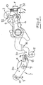
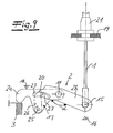
- a combined Bowden cable / lever unit for motor vehicle door locks is shown.
- This has a in Figs. 1, 3 and 4 indicated Bowden cable 1 and connected to the Bowden cable 1 actuator chain 2, 3, 4, 5.
- the actuator chain 2, 3, 4, 5 is in the context of the embodiment of an actuating lever 2 in the form of an external actuating lever 2, a main operating lever 3 and substantially a trigger lever 4, which operates on a trigger / locking element 6, 7 in the form of a locking mechanism of the catch 6 and pawl 7.
- a clutch lever 5 is still realized, which couples the main operating lever 3 with the external actuating lever 2 and an internal operating lever, not shown, to represent the function "child safety off". If, on the other hand, the "child safety on” position is desired, then the clutch lever 5 ensures that only the external actuating lever 2 can act on the actuating main lever 3, the actuating main lever 3 in both cases acting on the triggering lever 4 to open the locking mechanism 6, 7 in that both levers 3, 4 perform the clockwise movement indicated in FIG. As a result, the pawl 7 in the illustrations according to FIG. 3 and FIG. 4 also makes a clockwise movement, so that the catch 6 can release spring-assisted.
- the actuating element chain 2, 3, 4, 5 in the embodiment has three to be bridged column S1, S2 and S3. These gaps S1, S2 and S3 must be overcome by the Bowden cable 1, before even the pawl 7 begins in the clockwise direction shown in FIG. 3 by an arrow and the catch 6 triggering movement. This is done by a corresponding power stroke of the Bowden cable, which is connected according to the illustrations in Figs. 3 and 4 with a downward arrow, so that the first actuating element 2 and the external actuating lever 2 performs an indicated counterclockwise movement about its axis 8.
- the invention proposes essentially two measures.
- the third actuating element 4 or the triggering lever 4 is set up so that it operates on the triggering / blocking element 6, 7 or the locking mechanism 6, 7 essentially without play.
- the third actuating element or the release lever 4 has an end-side casing 9, which can be seen in particular in FIGS. 1 and 4.
- this casing 9 is a plastic sheath 9 which is applied over a certain length L on the trigger lever 4 end, in the region in which the trigger lever 4 on the pawl 7 and the trigger / locking element 6, 7 works.
- the sheath or plastic sheath 9 is made of a thermoplastic elastomer and can absorb in this way any shocks on the motor vehicle door lock without the pawl 7 is triggered.
- a housing-fixed stopper 10 cooperates.
- the sheath 9 and the release lever 4 in this area that is, between the pawl 7 and the housing-fixed stopper 10 designed so that they taken together fill a existing without the intervention of the lever 4 space F, and that is substantially free of play.
- a modified embodiment of the invention according to FIG. 4 provides that at least one actuating element 2, 3, 4, in the exemplary embodiment, the first actuating element 2 of the actuating element chain 2, 3, 4, 5, the clearance compensation for the Bowden cable 1 after a basic setting changed its contour.
- the actuating element 2 in question is an actuating lever 2 or the external actuating lever 2 is formed in two parts with a lock arm 2 a and a Bowdenzugarm 2 b. Both arms 2a, 2b are pivotally connected to each other via a rotation axis 11.
- a clearance compensation provides an adjustment 12 in the form of a cam, which changes an enclosed between the two arms 2a, 2b angle ⁇ .
- This angle ⁇ can be varied for an automatic clearance compensation with the help of a ball or other adjusting element 13, and that acted upon by a spring 14th
- the actuating lever 2 is able to change its contour by changing the angular position of the two arms 2a, 2b to each other.
- an attachment point 15 of the Bowden cable 1 on the first actuating element or external actuating lever 2 is changed in its position in such a way that the angle ⁇ enclosed between the two arms 2a, 2b becomes more acute-angled.
- the attachment point 15 moves away from its original position, as indicated in phantom in FIG.
- the distance of the attachment point 15 is increased for the Bowden cable of the Bowden cable and the Bowden cable 1 total set (again) taut.
- This can - as I said - be realized with the aid of the adjusting unit 12 or the adjusting element 13, both of which operate in such a way that with increasing clearance of the Bowden cable 1, the angle ⁇ between the two arms 2a, 2b is reduced.
- the lock arm 2a bears against the second actuating element 3, whereas the Bowden cable arm 2b carries the fastening point 15 for the Bowden cable 1 or its Bowden cable core.
- the adjusting unit 12 ensures that the main operating lever 3 reduces its play relative to the release lever 4. That is, the adjusting unit 12 changes the size of the gap S2.
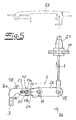
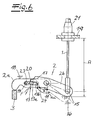
- a Bowden cable 1, 21 of Bowden cable core 1 and Bowden cable 21 is used to pivot a connected in an attachment point 15 actuating lever 2 about its axis of rotation 11 in the counterclockwise direction.
- the operating lever 2 changes the clearance compensation of the Bowden cable 1, 21 its contour, as can be seen with reference to FIG. That is, the operating lever 2 ensures that any elongations of the Bowden cable core 1 are automatically compensated during operation. For this purpose, the operating lever 2 ensures that the distance A between the Attachment point 15 for the Bowden cable core 1 and a stop 19 for the Bowden cable 21 is increased as clearance compensation.
- the actuating lever 2 is made in two parts with lock arm 2a and bottom pull 2b.
- both arms 2a, 2b change in the course of the clearance compensation to be described below the angle ⁇ enclosed between them.
- both arms 2a, 2b are pivotally connected to each other, via the axis or axis of rotation 11 for the actuating lever 2.
- This axis of rotation 11 is lock-fixed or mounted fixed to the housing.
- the Bowdenzugarm 2b has a nose 20 which cooperates with a counter-element 13 on the lock arm 2a.
- the counter element 13 is constructed in two parts in the context of the embodiment and is composed of a ball 13a and a merely indicated and optional and connected guide tip 13b together. Ball 13a and guide tip 13b can be moved in the longitudinal direction of the lock arm 2a in a recess 23 and are acted upon by a spring 14 in the direction of the nose 20 on Bowdenzugarm 2b.
- the nose 20 provides in conjunction with the counter element 13 for the transmission of power from the Bowden cable 1, 21 on the main operating lever 3. This is indicated by a force arrow F in Fig. 6.
- the guide tip 13b and consequently the position of the ball 13a and the counter element 13 in the guide 23 in the lock arm 2a is determined by a guide contour 24 on Bowdenzugarm 2b.
- the guide tip 13b and the counter element 13 abuts by the force of the spring 14 on the respective contour 24, which has a ⁇ with a decreasing angle inwardly curved area.
- the respective guide contour 24 changes the position of the counter element 13a via the guide tip 13b.
- two stops 16, 18 ensure that first of all a minimum angle ⁇ min between the two arms 2a, 2b is not undershot. This ensures the stop 16.
- the stopper 18 ensures that the lock arm 2a as a whole can not escape and in particular a change from the standby position shown in FIG. 5 in the working position of FIG. 6 is possible.
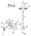
- the actuating lever 2 changes in a further embodiment for clearance compensation of the Bowden cable 1, 21 its contour, as can be seen with reference to FIG. That is, the operating lever 2 ensures that any elongations of the Bowden cable core 1 are automatically compensated during operation. For this purpose, the actuating lever 2 ensures that the distance A between the attachment point 15 for the Bowden cable core 1 and a stop 19 for the Bowden cable 21 is increased as a clearance compensation.
- the actuating lever 2 is made in two parts with lock arm 2a and bottom pull 2b. In fact, both arms are changing 2a, 2b in the course of the play compensation to be described below the angle ⁇ enclosed between them.
- both arms 2a, 2b are pivotally connected to each other, via the axis or axis of rotation 11 for the actuating lever 2. This axis of rotation 11 is lock-fixed or mounted fixed to the housing.
- the Bowdenzugarm 2b has a nose 20 which cooperates with a counter-element 13 on the lock arm 2a.
- the counter element 13 is constructed in one piece in the context of the embodiment and consists of a ball 13 a. This ball 13a can be displaced in the longitudinal direction of the lock arm 2a in a recess 23 and is acted upon by a spring 14 in the direction of the nose 20 on Bowdenzugarm 2b.
- the position of the ball 13a or of the counter element 13 in the guide 23 in the lock arm 2a is determined by a discrete guide contour 24 in the form of a step contour specified on Bowdenzugarm 2b.
- a discrete guide contour 24 in the form of a step contour specified on Bowdenzugarm 2b.
- two stops 16, 18 ensure that, first of all, a minimum angle between the two arms 2a, 2b is not undershot. This ensures the stop 16.
- the stop 18 ensures that the lock arm 2a as a whole can not escape and in particular a change from the standby position shown in FIG. 7 in the working position of FIG. 8 is possible.
- the actuating lever 2 changes its contour for compensating the play of the Bowden cable 1, 21.
- the actuating lever 2 is made in two parts with lock arm 2a and Bowdenzugarm 2b.
- both arms 2a, 2b change in the course of the clearance compensation to be described below the angle ⁇ enclosed between them.
- both arms 2a, 2b are pivotally connected to each other, via the axis or axis of rotation 11 for the actuating lever 2.
- This axis of rotation 11 is lock-fixed or mounted fixed to the housing.
- the Bowdenzugarm 2b has a nose 20 which cooperates with a counter-element 13 on the lock arm 2a.
- the counter-element 13 is constructed in the context of the embodiment as a on the lock arm 2a rotatably mounted about a pivot 25 guide lever 26 with a guide member 27 and can move in the direction of the lock arm 2a in a recess 23 and is by a spring, not shown in the direction the nose 20 applied to Bowdenzugarm 2b.
- the nose 20 provides in conjunction with the counter element 13 for the transmission of power from the Bowden cable 1, 21 on the main operating lever 3.
- the position of the counter element 13 in the guide 23 in the lock arm 2a is a Guiding contour 24 on Bowdenzugarm 2b given.
- the counter-element 13 rests against the relevant contour 24 by the force of the spring, which has a region curved inwardly with a decreasing angle.
- the position of the counter-element 13a is a Guiding contour 24 on Bowdenzugarm 2b given.
- two stops 16, 18 ensure that, first of all, a minimum angle between the two arms 2a, 2b is not undershot. This ensures the stop 16. In contrast, the stop 18 ensures that the lock arm 2a can not escape altogether.
Landscapes
- Engineering & Computer Science (AREA)
- General Engineering & Computer Science (AREA)
- Health & Medical Sciences (AREA)
- Oral & Maxillofacial Surgery (AREA)
- Mechanical Engineering (AREA)
- Lock And Its Accessories (AREA)
Claims (13)
- Agrégat combiné câble bowden/levier pour en particulier des fermetures de porte de véhicule, avec un câble bowden (1, 21) ainsi qu'une chaîne d'éléments d'actionnement (2, 3, 4, 5) y étant associée, avec un premier élément d'actionnement (2), un deuxième élément d'actionnement (3) et un troisième élément d'actionnement (4), la chaîne d'éléments d'actionnement (2, 3, 4, 5) présentant trois ou plus de fentes (S1, S2, S3) à ponter par une course de travail du câble bowden (1) jusqu'à l'excitation d'un élément de déclenchement/de blocage (6, 7) caractérisé en ce que le troisième élément d'actionnement (4) fonctionne pour l'essentiel sans jeu sur l'élément de déclenchement/de blocage (6, 7) de façon que le premier élément d'actionnement (2) règle le jeu restant dans la chaîne d'éléments d'actionnement (2, 3, 4, 5).
- Agrégat câble bowden /levier selon la revendication 1 caractérisé en ce que le troisième élément d'actionnement (4) présente une gaine (9) côté extrémité, en particulier une gaine (9) en plastique entre l'élément d'actionnement (4) concerné et l'élément de déclenchement/de blocage (6, 7).
- Agrégat câble bowden /levier selon la revendication 1 ou 2 caractérisé en ce que le troisième élément d'actionnement (4) pose côté extrémité, d'une part, sur une butée fixée au boîtier (10) et, d'autre part, à l'élément de déclenchement/de blocage (6, 7).
- Agrégat câble bowden /levier selon l'une des revendications 1 à 3 caractérisé en ce qu'au moins un élément d'actionnement (2) de la chaîne d'éléments d'actionnement (2, 3, 4, 5) modifie son contour pour compenser le jeu du câble bowden (1, 21) après une position initiale.
- Agrégat câble bowden /levier selon la revendication 4 caractérisé en ce que l'élément d'actionnement (2) concerné est formé de deux parties avec bras de serrure (2a) et bras de câble bowden (2b), les deux bras (2a, 2b) étant reliés entre eux par articulation rotative par l'intermédiaire d'un axe rotatif (11).
- Agrégat câble bowden /levier selon les revendications 4 et 5 caractérisé en ce que l'élément d'actionnement (2) modifie son contour de façon que la distance (A) entre le point de fixation (15) pour l'élément de câble bowden (1) et une butée (19) pour l'enveloppe de câble bowden (2) varie pour compenser le jeu.
- Agrégat câble bowden /levier selon l'une des revendications 4 à 6 caractérisé en ce que le bras de câble bowden (4) présente un taquet (20) qui, en relation avec un contre-élément (13) par position d'angle (α) des bras (2a, 2b) réglables entre eux, assure la transmission d'effort du câble bowden (1, 2)) vers l'élément d'actionnement 3 ou un mécanisme de sortie comparable.
- Agrégat câble bowden /levier selon l'une des revendications 4 à 7 caractérisé en ce que le contre-élément (13) est formé comme une bille (13a) logée de façon à pouvoir être déplacée dans le bras de serrure (2a) avec, le cas échéant, une pointe de guidage (13b) associée.
- Agrégat câble bowden /levier selon l'une des revendications 4 à 7 caractérisé en ce que le contre-élément (13) au bras de serrure (2a) est exécuté comme levier de guidage (26) rotatif.
- Agrégat câble bowden /levier selon l'une des revendications 4 à 9 caractérisé en ce que le contre-élément (13) au bras de serrure (2a) concourt avec un contour de guidage (24) situé au bras de câble bowden (2b).
- Agrégat câble bowden /levier selon l'une des revendications 4 à 10 caractérisé en ce que selon la position d'angle (α) des bras (2a, 2b) l'un par rapport à l'autre, le contour de guidage (24) modifie la position du contre-élément (13).
- Agrégat câble bowden /levier selon l'une des revendications 4 à 11 caractérisé en ce que plusieurs butées (16, 18) sont prévus pour le levier d'actionnement (2).
- Agrégat câble bowden /levier selon l'une des revendications 4 à 12 caractérisé en ce que le levier d'actionnement (4) fonctionne à l'état de livraison (Fig. 5) sans compensation de jeu et ne procède à la compensation de jeu automatique qu'à l'état de travail (Fig. 6).
Applications Claiming Priority (4)
| Application Number | Priority Date | Filing Date | Title |
|---|---|---|---|
| DE10331712 | 2003-07-11 | ||
| DE2003131712 DE10331712A1 (de) | 2003-07-11 | 2003-07-11 | Kombiniertes Bowdenzug-Hebelaggregat |
| DE2003137392 DE10337392A1 (de) | 2003-08-13 | 2003-08-13 | Kombiniertes Bowdenzug-/Hebelaggregat |
| DE10337392 | 2003-08-13 |
Publications (2)
| Publication Number | Publication Date |
|---|---|
| EP1496176A1 EP1496176A1 (fr) | 2005-01-12 |
| EP1496176B1 true EP1496176B1 (fr) | 2006-09-13 |
Family
ID=33453892
Family Applications (1)
| Application Number | Title | Priority Date | Filing Date |
|---|---|---|---|
| EP04015945A Expired - Lifetime EP1496176B1 (fr) | 2003-07-11 | 2004-07-07 | Commande par câble Bowden combiné avec un dispositif de levier |
Country Status (2)
| Country | Link |
|---|---|
| EP (1) | EP1496176B1 (fr) |
| DE (1) | DE502004001451D1 (fr) |
Family Cites Families (5)
| Publication number | Priority date | Publication date | Assignee | Title |
|---|---|---|---|---|
| FR1240022A (fr) * | 1959-07-21 | 1960-09-02 | Dispositif de sécurité pour la fermeture des portières de véhicules automobiles | |
| DE19620496A1 (de) * | 1996-05-21 | 1997-11-27 | Kuester & Co Gmbh | Vorrichtung zur Längenkorrektur oder -einstellung von Seilzügen, Betätigungszügen o. dgl. |
| DE10002215C1 (de) * | 2000-01-20 | 2001-10-04 | Huf Huelsbeck & Fuerst Gmbh | Fahrzeugtürgriff, ausgestattet mit einer Vorrichtung zur automatischen Längeneinstellung eines Seilzuges |
| DE10100636A1 (de) * | 2001-01-09 | 2002-07-18 | Huf Huelsbeck & Fuerst Gmbh | Vorrichtung zur Betätigung eines Verschlusses bei einer Tür oder einer Klappe, insbesondere bei Fahrzeugen |
| DE20201149U1 (de) * | 2002-01-26 | 2003-06-05 | Kirchhoff GmbH & Co.KG, 58553 Halver | Vorrichtung zur Sicherung einer Haube eines Kraftfahrzeuges |
-
2004
- 2004-07-07 DE DE502004001451T patent/DE502004001451D1/de not_active Expired - Lifetime
- 2004-07-07 EP EP04015945A patent/EP1496176B1/fr not_active Expired - Lifetime
Also Published As
| Publication number | Publication date |
|---|---|
| DE502004001451D1 (de) | 2006-10-26 |
| EP1496176A1 (fr) | 2005-01-12 |
Similar Documents
| Publication | Publication Date | Title |
|---|---|---|
| EP2326781B1 (fr) | Unité de serrure comportant des cliquets d'arrêt à plusieurs parties et un cliquet de blocage précontraint par ressort | |
| EP2596189B1 (fr) | Fermeture de porte de véhicule automobile | |
| EP3973122B1 (fr) | Arrangement de ferrure | |
| EP2342405B1 (fr) | Verrou pour véhicule à moteur | |
| DE10312304B4 (de) | Kraftffahrzeugschloß | |
| DE10230079A1 (de) | Türgriff-Montagekonstruktion | |
| EP3728770B1 (fr) | Dispositif de poignée de porte d'un véhicule automobile | |
| DE4418317C2 (de) | Blockiervorrichtung für einen Kraftfahrzeugtürverschluß | |
| EP3973130A1 (fr) | Ferrure pour meuble | |
| EP3044071B1 (fr) | Système pourvu d'au moins un corps élastique et d'au moins un élément de blocage formé séparément | |
| EP3060735A1 (fr) | Serrure de portière de véhicule automobile | |
| EP3027828A1 (fr) | Portière de véhicule automobile | |
| DE102017216920A1 (de) | Türgriffeinrichtung für eine Tür eines Kraftfahrzeugs, Tür, Kraftfahrzeug | |
| EP4112851B1 (fr) | Serrure de véhicule automobile, en particulier serrure de portière de véhicule automobile | |
| WO2017059836A1 (fr) | Serrure de porte de véhicule automobile avec amortisseur de mouvement | |
| DE102015001318A1 (de) | Betätigungseinrichtung für ein Kraftfahrzeugschloss | |
| AT403498B (de) | Fixiereinrichtung für brandschutztüren | |
| DE102004045283A1 (de) | Kraftfahrzeugschloß | |
| DE10339542B4 (de) | Kraftfahrzeugtürverschluss | |
| DE102014014619A1 (de) | Betätigungseinrichtung für ein Kraffahrzeugschloss | |
| DE10337392A1 (de) | Kombiniertes Bowdenzug-/Hebelaggregat | |
| EP4505088A1 (fr) | Arrangement d'articulation de connexion | |
| DE10013697A1 (de) | Feststellvorrichtung | |
| DE202010015399U1 (de) | Kraftfahrzeugtürverschluss | |
| EP3266964B1 (fr) | Système destiné à empêcher une ouverture accidentelle d'une porte ou d'un clapet de véhicule et véhicule équipé d'un tel système |
Legal Events
| Date | Code | Title | Description |
|---|---|---|---|
| PUAI | Public reference made under article 153(3) epc to a published international application that has entered the european phase |
Free format text: ORIGINAL CODE: 0009012 |
|
| AK | Designated contracting states |
Kind code of ref document: A1 Designated state(s): AT BE BG CH CY CZ DE DK EE ES FI FR GB GR HU IE IT LI LU MC NL PL PT RO SE SI SK TR |
|
| AX | Request for extension of the european patent |
Extension state: AL HR LT LV MK |
|
| 17P | Request for examination filed |
Effective date: 20050623 |
|
| AKX | Designation fees paid |
Designated state(s): DE FR |
|
| GRAP | Despatch of communication of intention to grant a patent |
Free format text: ORIGINAL CODE: EPIDOSNIGR1 |
|
| GRAS | Grant fee paid |
Free format text: ORIGINAL CODE: EPIDOSNIGR3 |
|
| GRAA | (expected) grant |
Free format text: ORIGINAL CODE: 0009210 |
|
| AK | Designated contracting states |
Kind code of ref document: B1 Designated state(s): DE FR |
|
| REF | Corresponds to: |
Ref document number: 502004001451 Country of ref document: DE Date of ref document: 20061026 Kind code of ref document: P |
|
| ET | Fr: translation filed | ||
| PLBE | No opposition filed within time limit |
Free format text: ORIGINAL CODE: 0009261 |
|
| STAA | Information on the status of an ep patent application or granted ep patent |
Free format text: STATUS: NO OPPOSITION FILED WITHIN TIME LIMIT |
|
| 26N | No opposition filed |
Effective date: 20070614 |
|
| PGFP | Annual fee paid to national office [announced via postgrant information from national office to epo] |
Ref country code: FR Payment date: 20100802 Year of fee payment: 7 |
|
| REG | Reference to a national code |
Ref country code: FR Ref legal event code: ST Effective date: 20120330 |
|
| PG25 | Lapsed in a contracting state [announced via postgrant information from national office to epo] |
Ref country code: FR Free format text: LAPSE BECAUSE OF NON-PAYMENT OF DUE FEES Effective date: 20110801 |
|
| P01 | Opt-out of the competence of the unified patent court (upc) registered |
Effective date: 20230529 |
|
| PGFP | Annual fee paid to national office [announced via postgrant information from national office to epo] |
Ref country code: DE Payment date: 20230720 Year of fee payment: 20 |
|
| REG | Reference to a national code |
Ref country code: DE Ref legal event code: R071 Ref document number: 502004001451 Country of ref document: DE |