EP1496182A2 - Schiebetürenanlage mit mehreren Schiebetüren - Google Patents
Schiebetürenanlage mit mehreren Schiebetüren Download PDFInfo
- Publication number
- EP1496182A2 EP1496182A2 EP04015745A EP04015745A EP1496182A2 EP 1496182 A2 EP1496182 A2 EP 1496182A2 EP 04015745 A EP04015745 A EP 04015745A EP 04015745 A EP04015745 A EP 04015745A EP 1496182 A2 EP1496182 A2 EP 1496182A2
- Authority
- EP
- European Patent Office
- Prior art keywords
- sliding door
- running rail
- sliding
- main shaft
- engagement
- Prior art date
- Legal status (The legal status is an assumption and is not a legal conclusion. Google has not performed a legal analysis and makes no representation as to the accuracy of the status listed.)
- Granted
Links
Images


Classifications
-
- E—FIXED CONSTRUCTIONS
- E05—LOCKS; KEYS; WINDOW OR DOOR FITTINGS; SAFES
- E05D—HINGES OR SUSPENSION DEVICES FOR DOORS, WINDOWS OR WINGS
- E05D15/00—Suspension arrangements for wings
- E05D15/56—Suspension arrangements for wings with successive different movements
- E05D15/58—Suspension arrangements for wings with successive different movements with both swinging and sliding movements
-
- E—FIXED CONSTRUCTIONS
- E05—LOCKS; KEYS; WINDOW OR DOOR FITTINGS; SAFES
- E05D—HINGES OR SUSPENSION DEVICES FOR DOORS, WINDOWS OR WINGS
- E05D15/00—Suspension arrangements for wings
- E05D15/06—Suspension arrangements for wings for wings sliding horizontally more or less in their own plane
- E05D15/0604—Suspension arrangements for wings for wings sliding horizontally more or less in their own plane allowing an additional movement
-
- E—FIXED CONSTRUCTIONS
- E05—LOCKS; KEYS; WINDOW OR DOOR FITTINGS; SAFES
- E05Y—INDEXING SCHEME ASSOCIATED WITH SUBCLASSES E05D AND E05F, RELATING TO CONSTRUCTION ELEMENTS, ELECTRIC CONTROL, POWER SUPPLY, POWER SIGNAL OR TRANSMISSION, USER INTERFACES, MOUNTING OR COUPLING, DETAILS, ACCESSORIES, AUXILIARY OPERATIONS NOT OTHERWISE PROVIDED FOR, APPLICATION THEREOF
- E05Y2201/00—Constructional elements; Accessories therefor
- E05Y2201/20—Brakes; Disengaging means; Holders; Stops; Valves; Accessories therefor
- E05Y2201/23—Actuation thereof
- E05Y2201/232—Actuation thereof by automatically acting means
-
- E—FIXED CONSTRUCTIONS
- E05—LOCKS; KEYS; WINDOW OR DOOR FITTINGS; SAFES
- E05Y—INDEXING SCHEME ASSOCIATED WITH SUBCLASSES E05D AND E05F, RELATING TO CONSTRUCTION ELEMENTS, ELECTRIC CONTROL, POWER SUPPLY, POWER SIGNAL OR TRANSMISSION, USER INTERFACES, MOUNTING OR COUPLING, DETAILS, ACCESSORIES, AUXILIARY OPERATIONS NOT OTHERWISE PROVIDED FOR, APPLICATION THEREOF
- E05Y2201/00—Constructional elements; Accessories therefor
- E05Y2201/20—Brakes; Disengaging means; Holders; Stops; Valves; Accessories therefor
- E05Y2201/252—Type of friction
- E05Y2201/26—Mechanical friction
-
- E—FIXED CONSTRUCTIONS
- E05—LOCKS; KEYS; WINDOW OR DOOR FITTINGS; SAFES
- E05Y—INDEXING SCHEME ASSOCIATED WITH SUBCLASSES E05D AND E05F, RELATING TO CONSTRUCTION ELEMENTS, ELECTRIC CONTROL, POWER SUPPLY, POWER SIGNAL OR TRANSMISSION, USER INTERFACES, MOUNTING OR COUPLING, DETAILS, ACCESSORIES, AUXILIARY OPERATIONS NOT OTHERWISE PROVIDED FOR, APPLICATION THEREOF
- E05Y2201/00—Constructional elements; Accessories therefor
- E05Y2201/20—Brakes; Disengaging means; Holders; Stops; Valves; Accessories therefor
- E05Y2201/262—Type of motion, e.g. braking
- E05Y2201/264—Type of motion, e.g. braking linear
-
- E—FIXED CONSTRUCTIONS
- E05—LOCKS; KEYS; WINDOW OR DOOR FITTINGS; SAFES
- E05Y—INDEXING SCHEME ASSOCIATED WITH SUBCLASSES E05D AND E05F, RELATING TO CONSTRUCTION ELEMENTS, ELECTRIC CONTROL, POWER SUPPLY, POWER SIGNAL OR TRANSMISSION, USER INTERFACES, MOUNTING OR COUPLING, DETAILS, ACCESSORIES, AUXILIARY OPERATIONS NOT OTHERWISE PROVIDED FOR, APPLICATION THEREOF
- E05Y2900/00—Application of doors, windows, wings or fittings thereof
- E05Y2900/10—Application of doors, windows, wings or fittings thereof for buildings or parts thereof
- E05Y2900/13—Type of wing
- E05Y2900/148—Windows
- E05Y2900/15—Balcony glazing
Definitions
- the invention relates to a sliding door system with several sliding doors according to the preamble of claim 1.
- Such sliding door systems for example, for the degree used by shop fronts of business premises, conservatories and balconies.
- the sliding doors made of glass, each with and without frames included and a continuous glass front for graduation z.
- each sliding door a locking or braking device but they are individually separated for each sliding door must be pressed.
- the invention is therefore the object of a sliding door system nachzusenten according to the preamble of claim 1 so that a particularly simple and automatic locking by braking Opening the sliding doors and / or wings is guaranteed over the opening is.
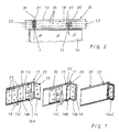
- An essential feature of the invention is that an automatic sequence when opening the sliding door system is such that the next the opening side sliding door from its closed position into one unfolded open position is pivoted.
- a Ausschwenkö réelle is arranged in the running rail through which one side of the sliding door with the caster wheel assembly running there can be swung out. This first sliding door will do so pivoted to the side and forms a first opening in the shop front.
- the invention provides that in the running rail remaining shaft of each sliding door arranged a braking device is that is operated with the pivoting movement of the sliding door and the pivoting wing locked relative to the running rail.
- the present invention is not limited to a sliding door system made of glass elements. It can all known Sliding door elements, such. B. solid wood, veneer, glass or Combination elements are used from this.
- the braking device from a pressure washer rotatably connected to the main shaft, which is arranged by means of liftable balls on an above the pressure disc, spring-loaded brake disc acts in braking engagement with the Running track can be brought.
- the braking device from a cam pin rotatably connected to the rotatable main shaft, the with an eccentric cam a rotatably mounted cam engages, which carries the spring-loaded brake disc, the Consequently, with its brake pad in engagement with the counter surface on the Running track comes.
- the sliding door system is described below in “hanging” design.
- the described arrangement can according to the invention also in “standing” construction rotated by 180 ° in the lower track - the means braking effect down - be provided.
- FIG. 1 schematically shows the opening of a sliding door system, wherein in a running rail 13, for example, five sliding 16th slidably indicated and only three of these sliding doors 16a-c closer are described.
- this track rail 13 On the horizontal, upper side one with the sliding door attachment too closing building opening is a running rail 13 on the ceiling or a base frame 30, wherein according to Figure 2, this track rail 13 at least two horizontally one below the other Has levels.
- a main shaft 1 moves arranged thereon with rollers 10, said main shaft 1, the inventive Braking device 21 is assigned.
- This upper rail level extends over the entire displacement length in the base frame 30.
- the swinging out takes place about the pivot axis 20 of the main shaft 1.
- the running rail 13 also forms several vertically below one another and mutually parallel tracks 35 in the rail plane out.
- Each sliding door 16 is thus in the direction of arrow 18 and in the opposite direction thereto slidably guided in the running rail 13. So this is a hanging storage of each sliding door, with each sliding door the two Waves 1, 15 are assigned.
- the invention is not limited to the arrangement of two Shafts each limited to a sliding door 16.
- There can also be several Waves are arranged parallel to each other, in particular at a distance to the main shaft 1 yet another arranged parallel thereto Shaft can be provided, but only the main shaft 1 the Braking device 21 according to the invention is assigned.
- each sliding door one Braking device 21 is assigned, which after a certain Ausschwenkweg each sliding door enters into action, thus serving as a pivot for the Swiveling movement of the sliding door serves and the folded in the package Sliding doors according to the right figure in Figure 1 in the issued Position securely locked.
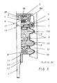
- FIG. 3 shows details of the braking device
- a clamping sleeve 12 is screwed, with their front approach 11 the entire structure of the Casters and the braking device holds together.
- the roller assembly consists in the embodiment shown in three levels superposed casters 10, 10 a, wherein all Casters 10, 10a in plain bearings or axial needle bearings 9 rotatably the main shaft 1 are stored.
- the braking device is essentially by a rotary coupling 19th formed during the rotation of the main shaft 1 about its longitudinal axis the spring-loaded brake disc 3 in engagement with a fixed to the running rail 13 associated guide bridge 14 brings.
- rotary joint which is able to axial Direction to raise a spring-loaded brake pad
- rotary joint which is able to axial Direction to raise a spring-loaded brake pad
- any rotary joint can be used, which is able to spring-loaded upon rotation of a main shaft preloaded brake disc 3 in engagement with a stationary to bring opposite arranged covering.
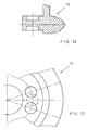
- a driving pin 8 engages through a Cross hole in the main shaft 1 and is in engagement with a pressure washer 7. This is shown in Figure 13 and 14 in more detail.
- the driving pin 8 rotatably with the pressure plate. 7 is coupled by it in a slot-shaped recess 41st engages which passes through the central bore 42 through which the Main shaft 1 passes through.
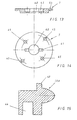
- the pressure disk 7 has arranged distributed uniformly around the circumference Ball mounts 45, in each of which a ball 6 engages.
- each ball 6 also engages in an associated ball socket 33 in a brake carrier 5 a.
- This brake carrier 5 is in the figures 10 to 12 shown.
- the guide bridge 14 is in this case firmly connected to the running rail 13.
- the brake disc 3 introduced into the toothing of the guide bridge 14 and there braced.
- the brake carrier 5 is in this case in the flanks 54 of the guide bridge 14 secured against rotation.
- the balls 6 are embedded in the brake carrier 5 and thus leave at Turning the thrust washer 7, the entire brake pack with high braking force be used.
- At least two balls should be used come the thrust washer in use with the brake carrier 5.
- the distribution should be made so that with left-right pivoting insert always at least 98 ° -shock the single wing is reached. This can, as in the present Thrust washer 7 arranged, with different bolt circles be achieved.
- a corrugated spring / shim 2 in this case supports the return the brake disc 3.
- the vertical load P is in the axial direction of the federal government of Main shaft above starting on the bearings 9 on the rollers 10, 10a in the running rail 13 initiated.
- FIG. 4 shows that the superimposed and in needle or Plain bearings 9 mounted rollers 10 on the swing-out bearing shaft 15 are rotatably mounted, in a so-called Schmiegungseingriff get to the associated running surfaces of the rail 13. This special intervention will be explained later with reference to FIG 24.
- FIG. 5 shows a section through the aforementioned clamping sleeve 12 without their approach 11.
- FIG. 6 shows a half-section which is upside down in comparison to FIG through the main shaft 1, where it can be seen that on the threaded neck 23, the clamping sleeve 12 is screwed according to Figure 5.
- the roller arrangement is mounted on the cylindrical shaft 24.
- the braking device 21 is arranged in the region of the cylindrical shaft 27.
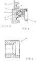
- FIGS. 7 to 9 show the previously mentioned brake disk 3, on whose Top side a toothing 31 is arranged, which is in braking engagement with the Bottom of the guide bridge 14 comes.
- brake carrier 5 The assignment of brake carrier 5 to the brake disc 3 and the stationary Guiding bridge 14 connected to running rail 13 is shown in FIG. 19 shown in more detail.
- Each ball 6 will be several hundredths of an inch more in the upper part of the ball Brake carrier held as comparatively in the associated ball seat 45 in the pressure plate 7th
- FIG. 15 shows the embodiment of an upper roller 10a, which is in its Size ratios relative to the rollers 10 for space saving reasons is designed to be smaller and therefore also reduced in size Has recess 44 for weight saving.
- Figures 16 and 17 show a roller 10, as in the lower levels of the track 13 is used.
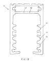
- FIG. 18 shows the profile of a running rail which essentially forms a U-shaped box profile. For example, here are three with each other lying tracks 35 present, with an upper profile section is completed by a central web 46, in which the guide bridge 14 is anchored.
- the anchoring of the guide bridge of Figure 19 is effected in that the dowel-like locking projections 34 at the top of the guide bridge 14 in associated recesses 55 in the region of the central web 46 of the Track 13 engage and anchored there, pegged or screwed are.
- Figures 20 to 22 show further details of the guide bridge. It is essentially a U-shaped profiled part to whose Bottom of a toothing 56 is arranged, which in meshing engagement comes with the teeth 31 of the brake disc 3.
- FIG. 19 shows that the brake disk 3 and the brake carrier respectively central bores 40, 32, through which the main shaft 1 reaches through.
- FIG. 23 shows a half section and a half plan view of the swing-out bearing shaft 15, which in section along with roller arrangement was shown in Figure 4.
- Each roller 10, 10 a has on the track 35 of the track rail 13th approximately rounded profile, but only between the positions 37, 38 a so-called osculation with the track 35 of the track rail 13 is received.
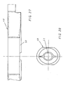
- Figures 25 to 30 show a further embodiment of a braking device 39.
- the braking device 39 consists of a again a bore in the main shaft passing through the cam pin 47, the cam plate 49 via the link opening 51 for Lifting brakes.
- the cam pin is approximately half round formed and has a comb-like, axially extending cam 48th on.
- the cam pin passes through the slotted opening 51 in the cam 49 as shown in FIG 28.
- the bottom of the cam plate 49 has a slope 50, which runs directly on the cam pin.
- FIG. 26 shows a half section through the previously mentioned one Bearing shaft 15 together with the roller arrangement.
Landscapes
- Engineering & Computer Science (AREA)
- Mechanical Engineering (AREA)
- Support Devices For Sliding Doors (AREA)
- Wing Frames And Configurations (AREA)
- Braking Arrangements (AREA)
- Gates (AREA)
- Power-Operated Mechanisms For Wings (AREA)
Abstract
Description
- Figur 1:
- schematisiert dargestellten einen Öffnungsvorgang der Schiebetüren-Anlage,
- Figur 2:
- schematisiert die Vorderansicht auf eine Laufschiene,
- Figur 3:
- einen Halbschnitt durch die Hauptwelle der Bremseinrichtung nach Figur 2,
- Figur 4:
- einen Halbschnitt durch die Schwenkrollenanordnung der Figur 2,
- Figur 5:
- einen Schnitt durch eine Spannhülse,
- Figur 6:
- einen Halbschnitt durch die Hauptwelle,
- Figur 7:
- eine Teilansicht der Bremsscheibe in Draufsicht,
- Figur 8:
- die Stimansicht der Bremsscheibe,
- Figur 9:
- ein Halbschnitt durch die Bremsscheibe,
- Figur 10:
- eine hälftige Draufsicht auf den Bremsträger,
- Figur 11:
- einen Schnitt durch den Bremsträger in Richtung der Linie XI-XI,
- Figur 12:
- schematisiert einen Schnitt durch die Kugelaufnahme im Bremsträger,
- Figur 13:
- einen Schnitt durch die Druckscheibe,
- Figur 14:
- eine Draufsicht auf die Druckscheibe,
- Figur 15:
- einen Halbschnitt durch eine obere Laufrolle,
- Figur 16:
- einen Halbschnitt durch eine untere Laufrolle,
- Figur 17:
- eine Draufsicht auf die Laufrolle nach Figur 16,
- Figur 18:
- eine Profilansicht der Laufschiene,
- Figur 19:
- eine perspektivische Darstellung der Zuordnung von Führungsbrücke, Bremsscheibe und Bremsträger,
- Figur 20:
- einen Teilschnitt durch die Führungsbrücke,
- Figur 21:
- eine Draufsicht auf die Führungsbrücke in Teildarstellung,
- Figur 22:
- eine Seitenansicht der Führungsbrücke,
- Figur 23:
- eine Halbdarstellung der ausschwenkbaren Lagerwelle mit einer Stirnseitenansicht,
- Figur 24:
- schematisiert den Eingriff einer Laufrolle in die Laufbahn der Laufschiene,
- Figur 25:
- einen Halbschnitt durch eine weitere Ausführungsform einer Hauptwelle mit einer anderen Bremseinrichtung,
- Figur 26:
- einen Halbschnitt durch die ausschwenkbare Lagerwelle,
- Figur 27:
- einen Schnitt durch eine Nockenscheibe zur Verwendung mit der Bremseinrichtung nach Figur 25,
- Figur 28:
- eine Draufsicht auf die Nockenscheibe nach Figur 27,
- Figur 29:
- einen Schnitt durch einen Nockenbolzen, und
- Figur 30:
- eine Teilansicht des Nockenbolzens nach Figur 29.
- 1
- Hauptwelle
- 2
- Ausgleichsscheibe
- 3
- Bremsscheibe
- 4
- Tellerfeder
- 5
- Bremsträger
- 6
- Kugel
- 7
- Druckscheibe
- 8
- Mitnahmestift
- 9
- Lager
- 10
- Laufrolle 10a Laufrolle oben
- 11
- Unterlegscheibe
- 12
- Spannhülse
- 13
- Laufschiene
- 14
- Führungsbrücke
- 15
- Lagerwelle (ausschwenkbar)
- 16
- Schiebetür
- 17
- Anschlag
- 18
- Pfeilrichtung
- 19
- Drehkupplung
- 20
- Schwenkachse
- 21
- Bremseinrichtung
- 22
- Ausschwenköffnung
- 23
- Gewindeansatz
- 24
- Schaft
- 25
- Schwenkrollenanordnung
- 26
- Bohrung
- 27
- Schaft
- 28
- Aufnahme
- 29
- Ausnehmung
- 30
- Grundrahmen
- 31
- Verzahnung
- 32
- Bohrung
- 33
- Kugelaufnahme
- 34
- Rastvorsprung
- 35
- Laufbahn
- 36
- Schmiegungsbereich
- 37
- Position
- 38
- Position
- 39
- Bremseinrichtung
- 40
- Bohrung (in 3 für 1 )
- 41
- Ausnehmung (in 7 für 8)
- 42
- Bohrung (in 7 für 1)
- 43
- Schräge
- 44
- Ausnehmung (in 10a für 9)
- 45
- Kugelaufnahme
- 46
- Mittelsteg
- 47
- Nockenbolzen
- 48
- Nocke
- 49
- Nockenscheibe
- 50
- Schräge
- 51
- Kulissenöffnung
- 52
- hintere Laufebene
- 53
- vordere Laufebene
- 54
- Flanke
- 55
- Ausnehmung
- 56
- Verzahnung
Claims (7)
- Schiebetüren-Anlage mit mehreren, in einer Laufschiene an Lagerwellen und Laufrollen hängend oder stehend gelagerten und in der Laufschiene (13) in horizontaler Richtung verschiebbaren Schiebetüren (16a-c), wobei an jeder Schiebetür mindestens zwei voneinander beabstandet angeordnete Lagerwellen (1, 15) mit zugeordneten Laufrollen (10, 10a) befestigt sind, und die Schiebetüren (16) durch Ausschwenken jeweils einer schiebetürseitigen Welle (15) aus der Laufschiene (13) heraus schwenkbar und zu einem Paket (16a-c) zusammen schiebbar sind, dadurch gekennzeichnet, dass
die Laufschiene (13) mindestens zwei in horizontaler Ebene untereinander versetzt angeordnete Laufebenen (52, 53) für die Laufrollen (10, 10a) der beiden Wellen (1,15) bildet,
dass die obere Laufebene (52) über die gesamte Schiebelänge durchgehend und die untere Laufebene (53) in Ausschwenkrichtung durch eine an der Ausschwenkstelle der Schiebetür (16) angeordnete Ausschwenköffnung (22) geöffnet ist,
dass durch die Ausschwenköffnung (22) hindurch die Schiebetür (16) ausschwenkbar ist, wobei die Lagerwelle (15) außer Eingriff mit der Laufschiene (13) kommt,
und dass bei Verschwenkung der Schiebetür (16) um die als Schwenkachse (20) in Eingriff mit der Laufschiene (13) verbleibenden Hauptwelle ( 1 ) eine Bremseinrichtung (21, 39) zwischen der Hauptwelle ( 1 ) und der Laufschiene (13) in Eingriff mit der Laufschiene kommt, die bei Zurückschwenken der Schiebetür (16) wieder außer Eingriff mit der Laufschiene (13) kommt. - Schiebetüren-Anlage nach Anspruch 1, dadurch gekennzeichnet, dass die Bremseinrichtung (21) eine drehfest mit der Hauptwelle (1) verbundenen Druckscheibe (7) aufweist, die nach Art einer Drehkupplung auf eine oberhalb der Druckscheibe (7) angeordnete, federbelastete Bremsscheibe (3) wirkt, die in Bremseingriff mit der Laufschiene (13) bringbar ist.
- Schiebetüren-Anlage nach Anspruch 2, dadurch gekennzeichnet, dass die Bremsscheibe (3) mittels Tellerfedern (4) in axialer Richtung anhebbar ist, welche in einem Bremsträger (5) eingebettet sind und sich in der Druckscheibe arretieren.
- Schiebetüren-Anlage nach Anspruch 3, dadurch gekennzeichnet, dass der Bremsträger (5) durch Kugeln (6) anhebbar ausgebildet ist, die in der Druckscheibe (7) angeordnet sind und sich am Bremsträger (5) anlegen.
- Schiebetüren-Anlage nach Anspruch 1, dadurch gekennzeichnet, dass die Bremseinrichtung (39) einen mit der Hauptwelle (1) drehfest verbundenen Nockenbolzen (47) aufweist, der mit einer exzentrischen Nocke (48) eine drehbar gelagerte Nockenscheibe (49) durchgreift, welche die federbelastete Bremsscheibe (3) trägt.
- Schiebetüren-Anlage nach einem der Ansprüche 1 bis 5, dadurch gekennzeichnet, dass die Laufschiene (13) im Querschnitt ein etwa kastenförmiges Profil aufweist, welches mehrere etwa elliptisch profilierte Laufbahnen (35) für den Eingriff der Laufrollen (10, 10a) ausbildet.
- Schiebetüren-Anlage nach einem der Ansprüche 1 bis 6, dadurch gekennzeichnet, dass jede Laufrolle (10, 10a) lediglich mit einer schrägen Berührungsfläche eine Schmiegung (36) mit der zugeordneten Fläche der Laufbahn (35) bildet.
Applications Claiming Priority (2)
| Application Number | Priority Date | Filing Date | Title |
|---|---|---|---|
| DE10330772A DE10330772A1 (de) | 2003-07-07 | 2003-07-07 | Schiebetürenanlage mit mehreren Schiebetüren |
| DE10330772 | 2003-07-07 |
Publications (3)
| Publication Number | Publication Date |
|---|---|
| EP1496182A2 true EP1496182A2 (de) | 2005-01-12 |
| EP1496182A3 EP1496182A3 (de) | 2008-10-01 |
| EP1496182B1 EP1496182B1 (de) | 2010-11-24 |
Family
ID=33441656
Family Applications (1)
| Application Number | Title | Priority Date | Filing Date |
|---|---|---|---|
| EP04015745A Expired - Lifetime EP1496182B1 (de) | 2003-07-07 | 2004-07-05 | Schiebetürenanlage mit mehreren Schiebetüren |
Country Status (5)
| Country | Link |
|---|---|
| EP (1) | EP1496182B1 (de) |
| AT (1) | ATE489526T1 (de) |
| DE (2) | DE10330772A1 (de) |
| DK (1) | DK1496182T3 (de) |
| ES (1) | ES2357058T3 (de) |
Cited By (8)
| Publication number | Priority date | Publication date | Assignee | Title |
|---|---|---|---|---|
| EP2202376A1 (de) | 2008-12-22 | 2010-06-30 | Weinor GmbH & Co. KG | Schiebedrehtürsystem |
| ITBS20090229A1 (it) * | 2009-12-21 | 2011-06-22 | Metalglas S R L | Sistema a pannelli mobili impacchettabili |
| EP2474697A2 (de) | 2011-01-11 | 2012-07-11 | Eduard Frunz | Schiebetürenanlage mit mehreren Schiebetüren |
| DE102011109525A1 (de) | 2011-08-05 | 2013-02-07 | Weinor Gmbh & Co. Kg | Schiebedrehtürsystem |
| DE102014100171B3 (de) * | 2014-01-09 | 2015-05-13 | Dorma Deutschland Gmbh | Schiebetürbremse |
| GB2533368A (en) * | 2014-12-18 | 2016-06-22 | Invisifold Ltd | A window |
| US9487985B2 (en) | 2015-05-07 | 2016-11-08 | Adam Conley | Movable closure system |
| DE102018218143A1 (de) | 2018-10-23 | 2020-04-23 | Mogla-Tech Ag | Bremslaufwerkanordnung für eine aufschwenkbare Schiebetüre |
Families Citing this family (2)
| Publication number | Priority date | Publication date | Assignee | Title |
|---|---|---|---|---|
| DE102006022184A1 (de) * | 2006-05-09 | 2007-11-15 | Grabo Gmbh | Führungs- und Drehlager für eine Klapp-/Schiebeverglasung |
| ES2427857B1 (es) * | 2012-04-30 | 2015-01-08 | C3 Systems, S.L. | Dispositivo de abatimiento y deslizamiento para paneles |
Citations (1)
| Publication number | Priority date | Publication date | Assignee | Title |
|---|---|---|---|---|
| WO1993008355A1 (en) | 1991-10-14 | 1993-04-29 | Sjoeholm Jarmo | Hinge arrangement, and use thereof |
Family Cites Families (3)
| Publication number | Priority date | Publication date | Assignee | Title |
|---|---|---|---|---|
| DE69214636T2 (de) * | 1991-03-27 | 1997-05-07 | Jarmo Vantaa Sjoeholm | Gleitelementsystem |
| SE9902620L (sv) * | 1999-07-08 | 2001-01-09 | Nordiska Balco Ab | Låsmekanism för låsnig av en glasskiva i en anordning för inglasning av en balkong |
| DE20022699U1 (de) * | 1999-09-20 | 2002-02-28 | Solarlux Aluminium Systeme GmbH, 49143 Bissendorf | Verriegelbares Dreh- und /oder Schiebeflügelsystem |
-
2003
- 2003-07-07 DE DE10330772A patent/DE10330772A1/de not_active Ceased
-
2004
- 2004-07-05 DK DK04015745.5T patent/DK1496182T3/da active
- 2004-07-05 AT AT04015745T patent/ATE489526T1/de active
- 2004-07-05 DE DE502004011916T patent/DE502004011916D1/de not_active Expired - Lifetime
- 2004-07-05 EP EP04015745A patent/EP1496182B1/de not_active Expired - Lifetime
- 2004-07-05 ES ES04015745T patent/ES2357058T3/es not_active Expired - Lifetime
Patent Citations (1)
| Publication number | Priority date | Publication date | Assignee | Title |
|---|---|---|---|---|
| WO1993008355A1 (en) | 1991-10-14 | 1993-04-29 | Sjoeholm Jarmo | Hinge arrangement, and use thereof |
Cited By (14)
| Publication number | Priority date | Publication date | Assignee | Title |
|---|---|---|---|---|
| EP2202376A1 (de) | 2008-12-22 | 2010-06-30 | Weinor GmbH & Co. KG | Schiebedrehtürsystem |
| DE102008063765A1 (de) | 2008-12-22 | 2010-09-09 | Weinor Gmbh & Co. Kg | Schiebetürsystem |
| ITBS20090229A1 (it) * | 2009-12-21 | 2011-06-22 | Metalglas S R L | Sistema a pannelli mobili impacchettabili |
| EP2474697A2 (de) | 2011-01-11 | 2012-07-11 | Eduard Frunz | Schiebetürenanlage mit mehreren Schiebetüren |
| DE102011002527A1 (de) | 2011-01-11 | 2012-07-12 | Eduard Frunz | Schiebetürenanlage mit mehreren Schiebetüren |
| DE102011109525A1 (de) | 2011-08-05 | 2013-02-07 | Weinor Gmbh & Co. Kg | Schiebedrehtürsystem |
| DE102014100171B3 (de) * | 2014-01-09 | 2015-05-13 | Dorma Deutschland Gmbh | Schiebetürbremse |
| GB2533368A (en) * | 2014-12-18 | 2016-06-22 | Invisifold Ltd | A window |
| US9487985B2 (en) | 2015-05-07 | 2016-11-08 | Adam Conley | Movable closure system |
| WO2016179599A1 (en) * | 2015-05-07 | 2016-11-10 | Adam Conley | Movable closure system |
| US9745787B2 (en) | 2015-05-07 | 2017-08-29 | Adam Conley | Movable closure system |
| DE102018218143A1 (de) | 2018-10-23 | 2020-04-23 | Mogla-Tech Ag | Bremslaufwerkanordnung für eine aufschwenkbare Schiebetüre |
| EP3643863A1 (de) | 2018-10-23 | 2020-04-29 | moGla-Tech AG | Bremslaufwerkanordnung für eine aufschwenkbare schiebetüre |
| DE102018218143B4 (de) | 2018-10-23 | 2020-07-09 | Mogla-Tech Ag | Bremslaufwerkanordnung für eine aufschwenkbare Schiebetüre |
Also Published As
| Publication number | Publication date |
|---|---|
| DE10330772A1 (de) | 2005-02-03 |
| EP1496182A3 (de) | 2008-10-01 |
| ATE489526T1 (de) | 2010-12-15 |
| EP1496182B1 (de) | 2010-11-24 |
| DE502004011916D1 (de) | 2011-01-05 |
| ES2357058T3 (es) | 2011-04-15 |
| DK1496182T3 (da) | 2011-03-14 |
Similar Documents
| Publication | Publication Date | Title |
|---|---|---|
| DE2421320C2 (de) | Aufhängevorrichtung für in Führungsschienen verschiebbare Flügel | |
| DE4435641C2 (de) | Schiebeflügel zum bedarfsweisen Verschließen, insbesondere einer offenen Seite von Balkonen, Wintergärten u. dgl. | |
| DE2332489A1 (de) | Vorrichtung zum hermetischen verschliessen mit einem rolltor | |
| WO1993007346A1 (de) | Feststell- und verriegelungseinheit | |
| AT519903B1 (de) | Schiene zur Führung eines Schlittens einer Möbeltüre | |
| EP1496182B1 (de) | Schiebetürenanlage mit mehreren Schiebetüren | |
| EP0936119B1 (de) | Schwenkschiebetür für Fahrzeuge | |
| EP2159345B1 (de) | Halterung für Verkleidungselemente | |
| EP3045638B1 (de) | Schiebe- und Drehflügelsystem | |
| AT523303B1 (de) | Führungsvorrichtung zur Führung eines Möbelteils | |
| DE3904026A1 (de) | Gleiteinlage fuer geschlossene zungenvorrichtungen wie auch fuer gleitflaechen fuer bewegliche herzstueckspitzen, sowie verfahren zum befestigen einer derartigen gleiteinlage an dem gleitbett von rillenschienenzungenvorrichtungen | |
| EP3480407B1 (de) | Vertikalschiebeelement | |
| EP3816383B1 (de) | Schiebetüranordnung | |
| EP1403459A2 (de) | Trennwand mit horizontal verschiebbaren Schiebeelementen | |
| DE9319844U1 (de) | Laufwerksanordnung mit Rollen für eine Schiebetür | |
| DE19539014A1 (de) | Schiebetürbeschlag | |
| DE8800862U1 (de) | Schiebetür | |
| EP1043469B1 (de) | Verschiebbares Wandelement, insbesondere für eine Schiebestapelwand | |
| EP3771793A1 (de) | Beschlag für eine schiebetür | |
| DE29713823U1 (de) | Schiebetürschließeinrichtung | |
| EP3757324B1 (de) | Schiebetürsystem | |
| DE29615631U1 (de) | Sicherungseinrichtung | |
| EP4219870B1 (de) | Rasthaken und rückhalteeinrichtung mit einem solchen rasthaken | |
| EP4343098A1 (de) | Druckneutrale fluchttür | |
| DE2416960C2 (de) | Schwenkzapfenausbildung |
Legal Events
| Date | Code | Title | Description |
|---|---|---|---|
| PUAI | Public reference made under article 153(3) epc to a published international application that has entered the european phase |
Free format text: ORIGINAL CODE: 0009012 |
|
| AK | Designated contracting states |
Kind code of ref document: A2 Designated state(s): AT BE BG CH CY CZ DE DK EE ES FI FR GB GR HU IE IT LI LU MC NL PL PT RO SE SI SK TR |
|
| AX | Request for extension of the european patent |
Extension state: AL HR LT LV MK |
|
| PUAL | Search report despatched |
Free format text: ORIGINAL CODE: 0009013 |
|
| AK | Designated contracting states |
Kind code of ref document: A3 Designated state(s): AT BE BG CH CY CZ DE DK EE ES FI FR GB GR HU IE IT LI LU MC NL PL PT RO SE SI SK TR |
|
| AX | Request for extension of the european patent |
Extension state: AL HR LT LV MK |
|
| 17P | Request for examination filed |
Effective date: 20090321 |
|
| AKX | Designation fees paid |
Designated state(s): AT BE BG CH CY CZ DE DK EE ES FI FR GB GR HU IE IT LI LU MC NL PL PT RO SE SI SK TR |
|
| 17Q | First examination report despatched |
Effective date: 20090807 |
|
| GRAP | Despatch of communication of intention to grant a patent |
Free format text: ORIGINAL CODE: EPIDOSNIGR1 |
|
| GRAJ | Information related to disapproval of communication of intention to grant by the applicant or resumption of examination proceedings by the epo deleted |
Free format text: ORIGINAL CODE: EPIDOSDIGR1 |
|
| GRAP | Despatch of communication of intention to grant a patent |
Free format text: ORIGINAL CODE: EPIDOSNIGR1 |
|
| GRAS | Grant fee paid |
Free format text: ORIGINAL CODE: EPIDOSNIGR3 |
|
| GRAA | (expected) grant |
Free format text: ORIGINAL CODE: 0009210 |
|
| AK | Designated contracting states |
Kind code of ref document: B1 Designated state(s): AT BE BG CH CY CZ DE DK EE ES FI FR GB GR HU IE IT LI LU MC NL PL PT RO SE SI SK TR |
|
| REG | Reference to a national code |
Ref country code: GB Ref legal event code: FG4D Free format text: NOT ENGLISH |
|
| REG | Reference to a national code |
Ref country code: CH Ref legal event code: EP |
|
| REG | Reference to a national code |
Ref country code: IE Ref legal event code: FG4D |
|
| REF | Corresponds to: |
Ref document number: 502004011916 Country of ref document: DE Date of ref document: 20110105 Kind code of ref document: P |
|
| REG | Reference to a national code |
Ref country code: CH Ref legal event code: PUE Owner name: EDUARD FRUNZ Free format text: FRUBAU DI FRUNZ EDUARD#VIA SALICI#6987 CASLANO (CH) -TRANSFER TO- EDUARD FRUNZ#VIA SAN MICHELE 64#6987 CASLANO (CH) |
|
| RAP2 | Party data changed (patent owner data changed or rights of a patent transferred) |
Owner name: FRUNZ, EDUARD |
|
| REG | Reference to a national code |
Ref country code: NL Ref legal event code: T3 |
|
| REG | Reference to a national code |
Ref country code: DK Ref legal event code: T3 |
|
| REG | Reference to a national code |
Ref country code: SE Ref legal event code: TRGR |
|
| REG | Reference to a national code |
Ref country code: NL Ref legal event code: SD Effective date: 20110222 |
|
| REG | Reference to a national code |
Ref country code: GB Ref legal event code: 732E Free format text: REGISTERED BETWEEN 20110310 AND 20110316 |
|
| REG | Reference to a national code |
Ref country code: ES Ref legal event code: FG2A Ref document number: 2357058 Country of ref document: ES Kind code of ref document: T3 Effective date: 20110415 |
|
| REG | Reference to a national code |
Ref country code: DE Ref legal event code: R081 Ref document number: 502004011916 Country of ref document: DE Owner name: FRUNZ, EDUARD, CH Free format text: FORMER OWNER: FRUBAU DI FRUNZ EDUARD, CASLANO, CH Effective date: 20110301 |
|
| PG25 | Lapsed in a contracting state [announced via postgrant information from national office to epo] |
Ref country code: CY Free format text: LAPSE BECAUSE OF FAILURE TO SUBMIT A TRANSLATION OF THE DESCRIPTION OR TO PAY THE FEE WITHIN THE PRESCRIBED TIME-LIMIT Effective date: 20101124 Ref country code: BG Free format text: LAPSE BECAUSE OF FAILURE TO SUBMIT A TRANSLATION OF THE DESCRIPTION OR TO PAY THE FEE WITHIN THE PRESCRIBED TIME-LIMIT Effective date: 20110224 Ref country code: PT Free format text: LAPSE BECAUSE OF FAILURE TO SUBMIT A TRANSLATION OF THE DESCRIPTION OR TO PAY THE FEE WITHIN THE PRESCRIBED TIME-LIMIT Effective date: 20110324 Ref country code: SI Free format text: LAPSE BECAUSE OF FAILURE TO SUBMIT A TRANSLATION OF THE DESCRIPTION OR TO PAY THE FEE WITHIN THE PRESCRIBED TIME-LIMIT Effective date: 20101124 Ref country code: FI Free format text: LAPSE BECAUSE OF FAILURE TO SUBMIT A TRANSLATION OF THE DESCRIPTION OR TO PAY THE FEE WITHIN THE PRESCRIBED TIME-LIMIT Effective date: 20101124 |
|
| REG | Reference to a national code |
Ref country code: FR Ref legal event code: TP |
|
| REG | Reference to a national code |
Ref country code: IE Ref legal event code: FD4D |
|
| PG25 | Lapsed in a contracting state [announced via postgrant information from national office to epo] |
Ref country code: GR Free format text: LAPSE BECAUSE OF FAILURE TO SUBMIT A TRANSLATION OF THE DESCRIPTION OR TO PAY THE FEE WITHIN THE PRESCRIBED TIME-LIMIT Effective date: 20110225 |
|
| PG25 | Lapsed in a contracting state [announced via postgrant information from national office to epo] |
Ref country code: IE Free format text: LAPSE BECAUSE OF FAILURE TO SUBMIT A TRANSLATION OF THE DESCRIPTION OR TO PAY THE FEE WITHIN THE PRESCRIBED TIME-LIMIT Effective date: 20101124 Ref country code: CZ Free format text: LAPSE BECAUSE OF FAILURE TO SUBMIT A TRANSLATION OF THE DESCRIPTION OR TO PAY THE FEE WITHIN THE PRESCRIBED TIME-LIMIT Effective date: 20101124 Ref country code: EE Free format text: LAPSE BECAUSE OF FAILURE TO SUBMIT A TRANSLATION OF THE DESCRIPTION OR TO PAY THE FEE WITHIN THE PRESCRIBED TIME-LIMIT Effective date: 20101124 |
|
| PG25 | Lapsed in a contracting state [announced via postgrant information from national office to epo] |
Ref country code: SK Free format text: LAPSE BECAUSE OF FAILURE TO SUBMIT A TRANSLATION OF THE DESCRIPTION OR TO PAY THE FEE WITHIN THE PRESCRIBED TIME-LIMIT Effective date: 20101124 Ref country code: RO Free format text: LAPSE BECAUSE OF FAILURE TO SUBMIT A TRANSLATION OF THE DESCRIPTION OR TO PAY THE FEE WITHIN THE PRESCRIBED TIME-LIMIT Effective date: 20101124 Ref country code: PL Free format text: LAPSE BECAUSE OF FAILURE TO SUBMIT A TRANSLATION OF THE DESCRIPTION OR TO PAY THE FEE WITHIN THE PRESCRIBED TIME-LIMIT Effective date: 20101124 |
|
| PLBI | Opposition filed |
Free format text: ORIGINAL CODE: 0009260 |
|
| PLAX | Notice of opposition and request to file observation + time limit sent |
Free format text: ORIGINAL CODE: EPIDOSNOBS2 |
|
| 26 | Opposition filed |
Opponent name: GRABO GMBH Effective date: 20110824 |
|
| REG | Reference to a national code |
Ref country code: DE Ref legal event code: R026 Ref document number: 502004011916 Country of ref document: DE Effective date: 20110824 |
|
| BERE | Be: lapsed |
Owner name: FRUBAU DI FRUNZ EDUARD Effective date: 20110731 |
|
| PLAF | Information modified related to communication of a notice of opposition and request to file observations + time limit |
Free format text: ORIGINAL CODE: EPIDOSCOBS2 |
|
| PG25 | Lapsed in a contracting state [announced via postgrant information from national office to epo] |
Ref country code: MC Free format text: LAPSE BECAUSE OF NON-PAYMENT OF DUE FEES Effective date: 20110731 |
|
| PLAF | Information modified related to communication of a notice of opposition and request to file observations + time limit |
Free format text: ORIGINAL CODE: EPIDOSCOBS2 |
|
| PG25 | Lapsed in a contracting state [announced via postgrant information from national office to epo] |
Ref country code: BE Free format text: LAPSE BECAUSE OF NON-PAYMENT OF DUE FEES Effective date: 20110731 |
|
| PLBB | Reply of patent proprietor to notice(s) of opposition received |
Free format text: ORIGINAL CODE: EPIDOSNOBS3 |
|
| PLAB | Opposition data, opponent's data or that of the opponent's representative modified |
Free format text: ORIGINAL CODE: 0009299OPPO |
|
| R26 | Opposition filed (corrected) |
Opponent name: GRABO GMBH Effective date: 20110824 |
|
| PG25 | Lapsed in a contracting state [announced via postgrant information from national office to epo] |
Ref country code: LU Free format text: LAPSE BECAUSE OF NON-PAYMENT OF DUE FEES Effective date: 20110705 |
|
| PG25 | Lapsed in a contracting state [announced via postgrant information from national office to epo] |
Ref country code: TR Free format text: LAPSE BECAUSE OF FAILURE TO SUBMIT A TRANSLATION OF THE DESCRIPTION OR TO PAY THE FEE WITHIN THE PRESCRIBED TIME-LIMIT Effective date: 20101124 |
|
| PG25 | Lapsed in a contracting state [announced via postgrant information from national office to epo] |
Ref country code: HU Free format text: LAPSE BECAUSE OF FAILURE TO SUBMIT A TRANSLATION OF THE DESCRIPTION OR TO PAY THE FEE WITHIN THE PRESCRIBED TIME-LIMIT Effective date: 20101124 |
|
| REG | Reference to a national code |
Ref country code: FR Ref legal event code: PLFP Year of fee payment: 12 |
|
| PLAB | Opposition data, opponent's data or that of the opponent's representative modified |
Free format text: ORIGINAL CODE: 0009299OPPO |
|
| R26 | Opposition filed (corrected) |
Opponent name: GRABO GMBH Effective date: 20110824 |
|
| PLAB | Opposition data, opponent's data or that of the opponent's representative modified |
Free format text: ORIGINAL CODE: 0009299OPPO |
|
| R26 | Opposition filed (corrected) |
Opponent name: INSOLVENZVERWALTERIN RECHTSANWAELTIN GESKE, ANJA ( Effective date: 20110824 |
|
| REG | Reference to a national code |
Ref country code: FR Ref legal event code: PLFP Year of fee payment: 13 |
|
| PLAB | Opposition data, opponent's data or that of the opponent's representative modified |
Free format text: ORIGINAL CODE: 0009299OPPO |
|
| R26 | Opposition filed (corrected) |
Opponent name: INSOLVENZVERWALTERIN RECHTSANWAELTIN GESKE, ANJA ( Effective date: 20110824 |
|
| PGFP | Annual fee paid to national office [announced via postgrant information from national office to epo] |
Ref country code: NL Payment date: 20160721 Year of fee payment: 13 |
|
| PLCK | Communication despatched that opposition was rejected |
Free format text: ORIGINAL CODE: EPIDOSNREJ1 |
|
| PGFP | Annual fee paid to national office [announced via postgrant information from national office to epo] |
Ref country code: DK Payment date: 20160722 Year of fee payment: 13 |
|
| PGFP | Annual fee paid to national office [announced via postgrant information from national office to epo] |
Ref country code: FR Payment date: 20160722 Year of fee payment: 13 |
|
| APAH | Appeal reference modified |
Free format text: ORIGINAL CODE: EPIDOSCREFNO |
|
| APBM | Appeal reference recorded |
Free format text: ORIGINAL CODE: EPIDOSNREFNO |
|
| APBP | Date of receipt of notice of appeal recorded |
Free format text: ORIGINAL CODE: EPIDOSNNOA2O |
|
| APBQ | Date of receipt of statement of grounds of appeal recorded |
Free format text: ORIGINAL CODE: EPIDOSNNOA3O |
|
| PGFP | Annual fee paid to national office [announced via postgrant information from national office to epo] |
Ref country code: GB Payment date: 20170906 Year of fee payment: 14 |
|
| PGFP | Annual fee paid to national office [announced via postgrant information from national office to epo] |
Ref country code: SE Payment date: 20170724 Year of fee payment: 14 |
|
| REG | Reference to a national code |
Ref country code: DK Ref legal event code: EBP Effective date: 20170731 |
|
| REG | Reference to a national code |
Ref country code: NL Ref legal event code: MM Effective date: 20170801 |
|
| REG | Reference to a national code |
Ref country code: FR Ref legal event code: ST Effective date: 20180330 |
|
| PG25 | Lapsed in a contracting state [announced via postgrant information from national office to epo] |
Ref country code: NL Free format text: LAPSE BECAUSE OF NON-PAYMENT OF DUE FEES Effective date: 20170801 |
|
| PG25 | Lapsed in a contracting state [announced via postgrant information from national office to epo] |
Ref country code: FR Free format text: LAPSE BECAUSE OF NON-PAYMENT OF DUE FEES Effective date: 20170731 |
|
| PG25 | Lapsed in a contracting state [announced via postgrant information from national office to epo] |
Ref country code: DK Free format text: LAPSE BECAUSE OF NON-PAYMENT OF DUE FEES Effective date: 20170731 |
|
| GBPC | Gb: european patent ceased through non-payment of renewal fee |
Effective date: 20180705 |
|
| PG25 | Lapsed in a contracting state [announced via postgrant information from national office to epo] |
Ref country code: GB Free format text: LAPSE BECAUSE OF NON-PAYMENT OF DUE FEES Effective date: 20180705 |
|
| PG25 | Lapsed in a contracting state [announced via postgrant information from national office to epo] |
Ref country code: SE Free format text: LAPSE BECAUSE OF NON-PAYMENT OF DUE FEES Effective date: 20180706 |
|
| PGFP | Annual fee paid to national office [announced via postgrant information from national office to epo] |
Ref country code: AT Payment date: 20190614 Year of fee payment: 16 |
|
| REG | Reference to a national code |
Ref country code: ES Ref legal event code: FD2A Effective date: 20201126 |
|
| PG25 | Lapsed in a contracting state [announced via postgrant information from national office to epo] |
Ref country code: ES Free format text: LAPSE BECAUSE OF NON-PAYMENT OF DUE FEES Effective date: 20190706 |
|
| REG | Reference to a national code |
Ref country code: AT Ref legal event code: MM01 Ref document number: 489526 Country of ref document: AT Kind code of ref document: T Effective date: 20200705 |
|
| REG | Reference to a national code |
Ref country code: DE Ref legal event code: R100 Ref document number: 502004011916 Country of ref document: DE |
|
| APBU | Appeal procedure closed |
Free format text: ORIGINAL CODE: EPIDOSNNOA9O |
|
| PG25 | Lapsed in a contracting state [announced via postgrant information from national office to epo] |
Ref country code: AT Free format text: LAPSE BECAUSE OF NON-PAYMENT OF DUE FEES Effective date: 20200705 |
|
| PLBN | Opposition rejected |
Free format text: ORIGINAL CODE: 0009273 |
|
| STAA | Information on the status of an ep patent application or granted ep patent |
Free format text: STATUS: OPPOSITION REJECTED |
|
| 27O | Opposition rejected |
Effective date: 20210429 |
|
| PGFP | Annual fee paid to national office [announced via postgrant information from national office to epo] |
Ref country code: IT Payment date: 20220729 Year of fee payment: 19 Ref country code: DE Payment date: 20220923 Year of fee payment: 19 |
|
| PGFP | Annual fee paid to national office [announced via postgrant information from national office to epo] |
Ref country code: CH Payment date: 20220801 Year of fee payment: 19 |
|
| REG | Reference to a national code |
Ref country code: DE Ref legal event code: R119 Ref document number: 502004011916 Country of ref document: DE |
|
| REG | Reference to a national code |
Ref country code: CH Ref legal event code: PL |
|
| PG25 | Lapsed in a contracting state [announced via postgrant information from national office to epo] |
Ref country code: DE Free format text: LAPSE BECAUSE OF NON-PAYMENT OF DUE FEES Effective date: 20240201 Ref country code: CH Free format text: LAPSE BECAUSE OF NON-PAYMENT OF DUE FEES Effective date: 20230731 |
|
| PG25 | Lapsed in a contracting state [announced via postgrant information from national office to epo] |
Ref country code: IT Free format text: LAPSE BECAUSE OF NON-PAYMENT OF DUE FEES Effective date: 20230705 |