EP1496232A2 - Méthode de commande d'un moteur à combustion interne - Google Patents
Méthode de commande d'un moteur à combustion interne Download PDFInfo
- Publication number
- EP1496232A2 EP1496232A2 EP04015476A EP04015476A EP1496232A2 EP 1496232 A2 EP1496232 A2 EP 1496232A2 EP 04015476 A EP04015476 A EP 04015476A EP 04015476 A EP04015476 A EP 04015476A EP 1496232 A2 EP1496232 A2 EP 1496232A2
- Authority
- EP
- European Patent Office
- Prior art keywords
- speed
- frequency
- nmot
- nkr
- pwm signal
- Prior art date
- Legal status (The legal status is an assumption and is not a legal conclusion. Google has not performed a legal analysis and makes no representation as to the accuracy of the status listed.)
- Granted
Links
- 238000000034 method Methods 0.000 title claims abstract description 16
- 238000002485 combustion reaction Methods 0.000 title claims description 19
- 238000002347 injection Methods 0.000 claims abstract description 24
- 239000007924 injection Substances 0.000 claims abstract description 24
- 230000003247 decreasing effect Effects 0.000 claims 1
- 239000000446 fuel Substances 0.000 abstract description 18
- 238000010586 diagram Methods 0.000 description 10
- 230000010355 oscillation Effects 0.000 description 5
- 230000006870 function Effects 0.000 description 4
- 101100478363 Saccharomyces cerevisiae (strain ATCC 204508 / S288c) BER1 gene Proteins 0.000 description 3
- 230000000694 effects Effects 0.000 description 3
- 239000002828 fuel tank Substances 0.000 description 3
- 230000001276 controlling effect Effects 0.000 description 2
- 238000013016 damping Methods 0.000 description 2
- 230000001419 dependent effect Effects 0.000 description 2
- 230000005284 excitation Effects 0.000 description 2
- 238000005457 optimization Methods 0.000 description 2
- 230000001105 regulatory effect Effects 0.000 description 2
- 239000000872 buffer Substances 0.000 description 1
- 238000006243 chemical reaction Methods 0.000 description 1
- 239000002826 coolant Substances 0.000 description 1
- 230000007423 decrease Effects 0.000 description 1
- 238000000605 extraction Methods 0.000 description 1
- 239000000314 lubricant Substances 0.000 description 1
- 230000000737 periodic effect Effects 0.000 description 1
- 230000000630 rising effect Effects 0.000 description 1
Images


Classifications
-
- F—MECHANICAL ENGINEERING; LIGHTING; HEATING; WEAPONS; BLASTING
- F02—COMBUSTION ENGINES; HOT-GAS OR COMBUSTION-PRODUCT ENGINE PLANTS
- F02D—CONTROLLING COMBUSTION ENGINES
- F02D41/00—Electrical control of supply of combustible mixture or its constituents
- F02D41/30—Controlling fuel injection
- F02D41/38—Controlling fuel injection of the high pressure type
- F02D41/3809—Common rail control systems
- F02D41/3836—Controlling the fuel pressure
- F02D41/3845—Controlling the fuel pressure by controlling the flow into the common rail, e.g. the amount of fuel pumped
-
- F—MECHANICAL ENGINEERING; LIGHTING; HEATING; WEAPONS; BLASTING
- F02—COMBUSTION ENGINES; HOT-GAS OR COMBUSTION-PRODUCT ENGINE PLANTS
- F02D—CONTROLLING COMBUSTION ENGINES
- F02D41/00—Electrical control of supply of combustible mixture or its constituents
- F02D41/20—Output circuits, e.g. for controlling currents in command coils
- F02D2041/202—Output circuits, e.g. for controlling currents in command coils characterised by the control of the circuit
- F02D2041/2024—Output circuits, e.g. for controlling currents in command coils characterised by the control of the circuit the control switching a load after time-on and time-off pulses
- F02D2041/2027—Control of the current by pulse width modulation or duty cycle control
-
- F—MECHANICAL ENGINEERING; LIGHTING; HEATING; WEAPONS; BLASTING
- F02—COMBUSTION ENGINES; HOT-GAS OR COMBUSTION-PRODUCT ENGINE PLANTS
- F02D—CONTROLLING COMBUSTION ENGINES
- F02D2200/00—Input parameters for engine control
- F02D2200/02—Input parameters for engine control the parameters being related to the engine
- F02D2200/06—Fuel or fuel supply system parameters
- F02D2200/0602—Fuel pressure
-
- F—MECHANICAL ENGINEERING; LIGHTING; HEATING; WEAPONS; BLASTING
- F02—COMBUSTION ENGINES; HOT-GAS OR COMBUSTION-PRODUCT ENGINE PLANTS
- F02D—CONTROLLING COMBUSTION ENGINES
- F02D2250/00—Engine control related to specific problems or objectives
- F02D2250/31—Control of the fuel pressure
-
- F—MECHANICAL ENGINEERING; LIGHTING; HEATING; WEAPONS; BLASTING
- F02—COMBUSTION ENGINES; HOT-GAS OR COMBUSTION-PRODUCT ENGINE PLANTS
- F02D—CONTROLLING COMBUSTION ENGINES
- F02D41/00—Electrical control of supply of combustible mixture or its constituents
- F02D41/02—Circuit arrangements for generating control signals
- F02D41/14—Introducing closed-loop corrections
- F02D41/1497—With detection of the mechanical response of the engine
-
- F—MECHANICAL ENGINEERING; LIGHTING; HEATING; WEAPONS; BLASTING
- F02—COMBUSTION ENGINES; HOT-GAS OR COMBUSTION-PRODUCT ENGINE PLANTS
- F02D—CONTROLLING COMBUSTION ENGINES
- F02D41/00—Electrical control of supply of combustible mixture or its constituents
- F02D41/20—Output circuits, e.g. for controlling currents in command coils
Definitions
- the invention relates to a method for controlling a Internal combustion engine with a common rail injection system according to the preamble of claim 1.
- a high-pressure pump delivers fuel from a fuel tank into a high-pressure accumulator.
- the high-pressure accumulator is called the high-pressure accumulator as a rail.
- the delivery flow of the high-pressure pump is controlled by a suction throttle certainly. Their position, in turn, is determined by an electronic one Control unit given as a function of input variables, z. B. the desired performance.
- the drive is the suction throttle as a PWM-modulated signal with a running constant frequency, z. B. 100 Hz.
- Conditional by this type of delivery of fuel is the rail consequently imprinted a periodic signal.
- the signal frequency corresponds the frequency of the PWM signal.
- the rail is periodically Taken from fuel, so that the periodically fluctuating High-pressure fuel is sampled. Is the fuel extraction z. B. with a frequency of 99 Hz, so arises Differential signal of 1 Hz. This means that the fuel high pressure a 1 Hz signal is superimposed.
- the invention is therefore the object of the pressure oscillations in the rail due to external excitation by the Reduce suction throttle.
- the invention provides that from the angular distance of two Injections, which defines the injection period, as well as the first frequency of the PWM signal (fundamental frequency) a critical Speed is calculated. Depending on the critical Speed is then set a speed range. At engine speed values within the speed range set the PWM signal to a second frequency. At engine speed values outside the speed range becomes the PWM signal set to the first frequency. In other words: The PWM signal is in the range of the critical speed of the first switched to the second frequency. For one increasing engine speed and for a falling engine speed each has its own speed range is provided. As well the invention provides that the frequency switching in the integer multiples of the critical speed becomes.
- the high-pressure control loop is stabilized.
- An additional optimization of high-pressure control parameters is not required.
- the P, I and D components of the high-pressure regulator remain unchanged.
- the effects on the hysteresis of the intake throttle are low, if the first and second frequencies differ only slightly, z. B. for the first frequency 100 Hz and for the second frequency 120 Hz.
- the time constants of the controlled system, d. H. the pumps with suction throttle and the rail in general are significantly larger than the reciprocal of the first and second frequency of the PWM signal, the switching takes place on the second frequency almost trouble-free.
- the effects on the high fuel pressure is therefore minimal.
- the invention offers the advantage that it is simple and little effort later in an electronic Control unit of an internal combustion engine can be applied.
- FIG. 1 shows an internal combustion engine 1.
- the fuel over a Injected common rail system.
- the operation of the internal combustion engine 1 is by a electronic control unit (EDC) 4 regulated.
- the electronic Control unit 4 contains the usual components of a Microcomputer system, for example a microprocessor, I / O blocks, buffers and memory blocks (EEPROM, RAM).
- I / O blocks I / O blocks
- buffers and memory blocks EEPROM, RAM
- EEPROM EEPROM
- RAM memory blocks
- the memory modules are for the operation of the internal combustion engine 1 relevant operating data in maps / characteristic curves applied. About this calculates the electronic Control unit 4 from the input variables, the output variables.
- the following input variables are exemplary represented: an actual rail pressure pCR (IST), which by means of a Rail pressure sensor 5 is measured, a speed signal nMOT the internal combustion engine 1, an input E and a signal FW for performance specification by the operator.
- Under the input E are, for example, the charge air pressure of a turbocharger and the temperatures of the coolants / lubricants and the Fuel subsumes.
- FIG 1 are as outputs of the electronic control unit 4 a signal ADV for controlling the suction throttle and a Output size A shown.
- the output size A is Representative of the other control signals to the controller and control of the internal combustion engine 1, for example the Injection start SB and the injection duration SD.
- the signal ADV is executed in practice as a pulse width modulated signal (PWM).
- PWM pulse width modulated signal
- FIG. 2 shows a high-pressure control circuit.
- the input quantity corresponds to the setpoint of the rail pressure pCR (SL).
- the output quantity corresponds to the raw value of the rail pressure pCR.
- From the raw value of the rail pressure pCR is filtered by means of a filter 12, the rail pressure actual value pCR (IST) is determined. This one is with compared to the set point pCR (SL) at a summation point, from which the control deviation dp results.
- From the control deviation dp is a manipulated variable by means of a high-pressure regulator 8 calculated.
- the manipulated variable corresponds to a volume flow qV.
- the physical unit of the volume flow can, for. B. Be liter / minute.
- the volume flow qV the calculated target consumption is added.
- the volume flow qV corresponds to the input quantity for a limitation 9.
- the limitation 9 can be speed-dependent, Input size nMOT.
- the output qV (SL) of the limit 9 is then converted in a function block 10 into a PWM signal. During conversion, fluctuations in the operating voltage and the fuel pressure taken into account.
- the solenoid coil of the suction throttle then becomes the PWM signal applied. This changes the path of the magnetic core, whereby the flow rate of the high-pressure pump freely influenced becomes.
- the pumps 3 with suction throttle and the rail 6 correspond the controlled system 11. From the rail 6 is via the injectors 7 a volume flow qV (VER) dissipated. This is the control loop closed.
- FIG. 3 is a timing diagram for a speed-up run an internal combustion engine with sixteen cylinders.
- the injection period is 45 degrees based on the crankshaft. It was based on this time diagram a PWM signal with a first frequency f1 of 102.4 Hz.
- On the ordinates are the values of the rail pressure pCR and the values of the engine speed nMOT are plotted. As abscissa different time values are shown.
- the angular distance between two injections, the injection period is the number of cylinders of the Internal combustion engine dependent. In a 20-cylinder internal combustion engine can the angular distance z. B. 72 degrees.
- the engine speed exceeds nMOT at point A the speed value 768 revolutions / minute.
- This speed value corresponds to an injection frequency of 102.4 Hz. This frequency is identical to the first one Frequency of the PWM signal.
- the rail pressure actual value pCR (IST) shows from the time t6 significant pressure oscillations with increasing Amplutide. The maximum amplitude (peak / peak) is about 40 bar. After time t8 decreases again the amplitude.
- FIG 4 is a speed diagram for an increasing engine speed (Arrow direction to the right) and a falling engine speed (Arrow pointing to the left).
- a rising or falling engine speed can z. B. based on the speed gradient nGRAD be identified.
- the invention now provides that from the injection period and the first Frequency f1 of the PWM signal calculates a critical speed nKR becomes.
- the critical speed nKR corresponds to z. Eg 768 Revolutions / minute, corresponding to point A of Figure 3.
- first speed range BER1 and a second speed range BER2 set can be z. B. 120 revolutions / minute be.
- the first speed range BER1 is replaced by a defined first limit value n1 and a second limit value n2.
- the second speed range BER2 is replaced by a third Limit n3 and a fourth limit n4 defined.
- first n1 and third limits n3 are for smaller engine speed values set as the critical speed nKR.
- the second n2 and fourth limit n4 are at higher engine speed values set as the critical speed nKR.
- the third limit n3 is opposite the first threshold n1 by a first hysteresis value Hyst1 shifted to smaller engine speed values.
- the value of the first hysteresis Hyst1 can be z. B. 20 revolutions / minute be. It prevents a back and forth between both frequencies in steady state operation.
- nKR critical speed
- the critical speed nKR will increase with increasing engine speed nMOT from the second frequency f2 back to the first frequency f1 is switched back when the second limit n2 is exceeded.
- a switch back to the second frequency f2 takes place at falling speed only when the below the fourth limit n4.
- the fourth limit n4 is a second compared to the third threshold n3 Hysteresis value Hyst2 shifted to smaller engine speed values.
- the two speed ranges arise BER1 and BER2 within which the second frequency f2 is valid is. Outside these speed ranges is the frequency of the PWM signal identical to the first frequency f1. Is that the first frequency f1 z. B.
- Figures 5A and 5B illustrate as state diagrams again the switching mechanism of the first frequency f1 to the second frequency f2 and vice versa.
- FIG. 5A shows that for engine speeds nMOT below the critical speed nKR from the first f1 to the second Frequency f2 is switched when the engine speed nMOT is greater than the first limit n1. On the first frequency f1 is then switched back when the engine speed nMOT becomes smaller than the third threshold n3, accordingly the difference of the first limit value n1 and the first hysteresis Hyst1.
- FIG. 5B shows that for engine speeds nMOT above the critical speed nKR from the second f2 to the first Frequency f1 is switched when the engine speed nMOT exceeds the second limit n2. On the second frequency f2 is then switched back when the engine speed nMOT becomes smaller than the fourth limit n4, accordingly the difference of the second threshold n2 minus the second Hysteresis Hyst2.
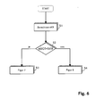
- FIG. 6 shows a program flow chart.
- the critical speed nKR from the angular distance of two injections, ie the injection period, and the first frequency f1 of the PWM signal.
- S2 it is checked if the engine speed nMOT is less than the critical speed nKR. is this smaller, then S3 becomes the program schedule of the figure 7 branches. If this is larger, then S4 becomes the program flowchart of Figure 8 branches.
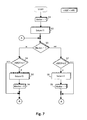
- FIG 7 is a program flowchart for engine speeds nMOT below the critical speed nKR.
- the PWM signal To the starting of the internal combustion engine is at S1 on a flag One set.
- the PWM signal then becomes the first one Frequency f1 set, z. B. 102.4 Hz. Then it is checked at S3, whether the flag has the value one. If this is the case, then is checked at S4, if the engine speed nMOT the first Limit has exceeded n1. If this is the case, then set the frequency of the PWM signal to the second frequency f2, Step S5. The PWM signal is thus switched.
- the flag is set to the value zero and branched to point A. If the query at S4 is negative, then is branched directly to point A.
- step S7 it is checked in step S7 whether the engine speed nMOT the third limit value n3, corresponding to the difference the first limit n1 minus the first hysteresis Hyst1. If this is the case, then the frequency of the PWM signal again set to the value f1, step S8. in the Step S9 then the flag back to the value One set and branched back to point A. Is the query negative at S7, branching directly to point A.
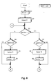
- FIG. 8 is a program schedule for engine speeds nMOT above the critical speed nKR shown.
- First a flag is set to the value one.
- the PWM signal is set to the second frequency f2.
- the S3 it is checked whether the flag has the value one. Is this the Case, it is checked at S4, if the engine speed nMOT the exceeds second limit n2. If the result is positive the PWM signal is set to the first frequency f1 and the Flag set to zero, S5 and S6. Subsequently is branched to the program point A. Is the query at S4 negative, it is branched directly to the point A.
- S7 checks whether the engine speed nMOT is lower than the fourth threshold n4 is equal to the difference second limit n2 minus the second hysteresis Hyst2. is If so, at S8 the PWM signal becomes the second one Frequency f2 set and the flag set to the value one, S9. Thereafter, the program point A is branched again. Is the Query at S7 negative, it is branched directly to point A.
Landscapes
- Engineering & Computer Science (AREA)
- Chemical & Material Sciences (AREA)
- Combustion & Propulsion (AREA)
- Mechanical Engineering (AREA)
- General Engineering & Computer Science (AREA)
- Electrical Control Of Air Or Fuel Supplied To Internal-Combustion Engine (AREA)
Applications Claiming Priority (2)
| Application Number | Priority Date | Filing Date | Title |
|---|---|---|---|
| DE10330466 | 2003-07-05 | ||
| DE10330466A DE10330466B3 (de) | 2003-07-05 | 2003-07-05 | Verfahren zur Regelung einer Brennkraftmaschine |
Publications (3)
| Publication Number | Publication Date |
|---|---|
| EP1496232A2 true EP1496232A2 (fr) | 2005-01-12 |
| EP1496232A3 EP1496232A3 (fr) | 2006-09-06 |
| EP1496232B1 EP1496232B1 (fr) | 2008-08-27 |
Family
ID=33016468
Family Applications (1)
| Application Number | Title | Priority Date | Filing Date |
|---|---|---|---|
| EP04015476A Expired - Lifetime EP1496232B1 (fr) | 2003-07-05 | 2004-07-01 | Méthode de commande d'un moteur à combustion interne |
Country Status (3)
| Country | Link |
|---|---|
| US (1) | US7017549B2 (fr) |
| EP (1) | EP1496232B1 (fr) |
| DE (1) | DE10330466B3 (fr) |
Families Citing this family (19)
| Publication number | Priority date | Publication date | Assignee | Title |
|---|---|---|---|---|
| DE102004023365B4 (de) * | 2004-05-12 | 2007-07-19 | Mtu Friedrichshafen Gmbh | Verfahren zur Druck-Regelung eines Speichereinspritzsystems |
| DE102004061474B4 (de) * | 2004-12-21 | 2014-07-17 | Mtu Friedrichshafen Gmbh | Verfahren und Einrichtung zur Regelung des Raildrucks |
| DE102005029138B3 (de) * | 2005-06-23 | 2006-12-07 | Mtu Friedrichshafen Gmbh | Steuer- und Regelverfahren für eine Brennkraftmaschine mit einem Common-Railsystem |
| DE102006040441B3 (de) | 2006-08-29 | 2008-02-21 | Mtu Friedrichshafen Gmbh | Verfahren zum Erkennen des Öffnens eines passiven Druck-Begrenzungsventils |
| DE102006049266B3 (de) | 2006-10-19 | 2008-03-06 | Mtu Friedrichshafen Gmbh | Verfahren zum Erkennen eines geöffneten passiven Druck-Begrenzungsventils |
| DE102007027943B3 (de) * | 2007-06-18 | 2008-10-16 | Mtu Friedrichshafen Gmbh | Verfahren zur Regelung des Raildrucks während eines Startvorgangs |
| DE602007007331D1 (de) | 2007-09-13 | 2010-08-05 | Magneti Marelli Spa | Verfahren zur Steuerung eines Direkteinspritzungsystems von der Common-Rail Art mit einem Absperrventil um die Flussrate einer Hochdruckkraftstoffpumpe zu regeln |
| DE102008058721B4 (de) | 2008-11-24 | 2011-01-05 | Mtu Friedrichshafen Gmbh | Steuerungs- und Regelungsverfahren für eine Brennkraftmaschine mit einem Common-Railsystem |
| DE102008058720A1 (de) * | 2008-11-24 | 2010-05-27 | Mtu Friedrichshafen Gmbh | Steuerungs- und Regelungsverfahren für eine Brennkraftmaschine mit einem Common-Railsystem |
| DE102009031528B3 (de) | 2009-07-02 | 2010-11-11 | Mtu Friedrichshafen Gmbh | Verfahren zur Steuerung und Regelung einer Brennkraftmaschine |
| DE102009031527B3 (de) * | 2009-07-02 | 2010-11-18 | Mtu Friedrichshafen Gmbh | Verfahren zur Steuerung und Regelung einer Brennkraftmaschine |
| DE102009031529B3 (de) * | 2009-07-02 | 2010-11-11 | Mtu Friedrichshafen Gmbh | Verfahren zur Steuerung und Regelung einer Brennkraftmaschine |
| DE102009050467B4 (de) | 2009-10-23 | 2017-04-06 | Mtu Friedrichshafen Gmbh | Verfahren zur Steuerung und Regelung einer Brennkraftmaschine |
| DE102009051389A1 (de) | 2009-10-30 | 2011-05-26 | Mtu Friedrichshafen Gmbh | Verfahren zur Steuerung und Regelung einer Brennkraftmaschine in V-Anordnung |
| DE102009051390B4 (de) | 2009-10-30 | 2015-10-22 | Mtu Friedrichshafen Gmbh | Verfahren zur Steuerung und Regelung einer Brennkraftmaschine |
| US8456115B2 (en) * | 2011-02-23 | 2013-06-04 | Deere & Company | Method and system for controlling an electric motor with variable switching frequency at variable operating speeds |
| GB2489463A (en) * | 2011-03-29 | 2012-10-03 | Gm Global Tech Operations Inc | Method of controlling fuel injection in a common rail engine |
| DE102014209875A1 (de) * | 2014-05-23 | 2015-11-26 | Robert Bosch Gmbh | Verfahren zur Ansteuerung eines elektromagnetischen Druckregelventils |
| WO2017064360A1 (fr) * | 2015-10-16 | 2017-04-20 | Wärtsilä Finland Oy | Procédé dans une procédure de démarrage d'un moteur à piston à combustion interne pourvu d'un système d'injection à rampe commune |
Citations (1)
| Publication number | Priority date | Publication date | Assignee | Title |
|---|---|---|---|---|
| DE4020654C2 (de) | 1990-06-29 | 1999-12-16 | Bosch Gmbh Robert | Regelverfahren in Verbindung mit einer Brennkraftmaschine und/oder einem Kraftfahrzeug und Regelvorrichtung zur Durchführung des Regelverfahrens |
Family Cites Families (7)
| Publication number | Priority date | Publication date | Assignee | Title |
|---|---|---|---|---|
| DE69925783T2 (de) * | 1998-04-15 | 2006-05-11 | Denso Corp., Kariya | Brennstoffeinspritzsystem für eine Brennkraftmaschine |
| JP3500969B2 (ja) * | 1998-07-03 | 2004-02-23 | 株式会社日立製作所 | 電子スロットル制御装置 |
| JP2000297474A (ja) * | 1999-04-15 | 2000-10-24 | Oimatsu Sangyo:Kk | 壁用パネル |
| IT1308779B1 (it) * | 1999-07-02 | 2002-01-10 | Elasis Sistema Ricerca Fiat | Dispositivo di regolazione della pressione di mandata di una pompa,adesempio per l'alimentazione di combustibile ad un motore a combustione |
| US6636783B2 (en) * | 2001-06-05 | 2003-10-21 | Honda Giken Kogyo Kabushiki Kaisha | Control system for throttle valve actuating device |
| JP3805648B2 (ja) * | 2001-06-14 | 2006-08-02 | 三菱電機株式会社 | エンジン用吸気量制御装置 |
| JP4841772B2 (ja) * | 2001-09-28 | 2011-12-21 | いすゞ自動車株式会社 | コモンレール式燃料噴射制御装置 |
-
2003
- 2003-07-05 DE DE10330466A patent/DE10330466B3/de not_active Expired - Lifetime
-
2004
- 2004-07-01 EP EP04015476A patent/EP1496232B1/fr not_active Expired - Lifetime
- 2004-07-06 US US10/883,975 patent/US7017549B2/en not_active Expired - Lifetime
Patent Citations (1)
| Publication number | Priority date | Publication date | Assignee | Title |
|---|---|---|---|---|
| DE4020654C2 (de) | 1990-06-29 | 1999-12-16 | Bosch Gmbh Robert | Regelverfahren in Verbindung mit einer Brennkraftmaschine und/oder einem Kraftfahrzeug und Regelvorrichtung zur Durchführung des Regelverfahrens |
Also Published As
| Publication number | Publication date |
|---|---|
| DE10330466B3 (de) | 2004-10-21 |
| EP1496232A3 (fr) | 2006-09-06 |
| US20050051137A1 (en) | 2005-03-10 |
| US7017549B2 (en) | 2006-03-28 |
| EP1496232B1 (fr) | 2008-08-27 |
Similar Documents
| Publication | Publication Date | Title |
|---|---|---|
| EP1496232B1 (fr) | Méthode de commande d'un moteur à combustion interne | |
| EP0109545B1 (fr) | Dispositif pour amortir les irrégularités de marche d'un moteur à combustion interne dans un véhicule | |
| DE102009056381B4 (de) | Verfahren zur Steuerung und Regelung einer Brennkraftmaschine | |
| EP2006521B1 (fr) | Procédé de réglage de la pression du rail lors d'un processus de démarrage | |
| EP1896712B1 (fr) | Procede de commande et de regulation pour un moteur a combustion interne equipe d'un systeme common rail | |
| EP0930426B1 (fr) | Méthode pour prédéterminer la référence de pression d'un système d'injection de carburant avec accumulateur | |
| EP2225447A1 (fr) | Procédé de régulation d'un moteur à gaz stationnaire | |
| DE10221681B4 (de) | Verfahren zur Regelung einer Brennkraftmaschinen-Generator-Einheit | |
| EP2358988B1 (fr) | Procédé de commande et de régulation d'un moteur à combustion interne équipé d'un système à rampe commune | |
| DE10315881B4 (de) | Verfahren zur Drehzahl-Regelung | |
| DE102008042783A1 (de) | Verfahren und Vorrichtung zum Betreiben einer Antriebseinheit | |
| DE10302263B3 (de) | Verfahren zur Drehzahl-Regelung einer Brennkraftmaschine | |
| EP1568874A2 (fr) | Procédé et système de commande de débit volumétrique dans un système d'injection de carburant d' un moteur à combustion interne | |
| EP1281860A2 (fr) | Système d'injection pour moteur à combustion interne et procédé de fonctionnement d'un tel système | |
| DE19809010A1 (de) | Kraftstoffeinspritzsteuereinrichtung für eine Brennkraftmaschine mit innerer Verbrennung | |
| DE102004015973B3 (de) | Verfahren zur Steuerung und Regelung einer Brennkraftmaschinen-Generator-Einheit | |
| EP2718556B1 (fr) | Procédé de régulation de la pression de rampe | |
| DE102006008356B4 (de) | Verfahren zur Leistungsbegrenzung einer Brennkraftmaschine | |
| DE102008054757A1 (de) | Verfahren zum Adaptieren eines Schleppmoments oder eines Verlustmoments eines Antriebsmotors | |
| EP0128523A2 (fr) | Procédé d'utilisation de machine à combustion | |
| DE10149960C1 (de) | Verfahren, Computerprogramm, Steuer- und/oder Regelgerät zum Betreiben einer Brennkraftmaschine, sowie Brennkraftmaschine | |
| DE102008058721B4 (de) | Steuerungs- und Regelungsverfahren für eine Brennkraftmaschine mit einem Common-Railsystem | |
| DE10305878B4 (de) | Verfahren zum Betreiben einer Brennkraftmaschine, Steuer- und/oder Regelgerät für eine Brennkraftmaschine, Computerprogramm und elektrisches Speichermedium einer Brennkraftmaschine | |
| DE102009027806A1 (de) | Verfahren zum Betreiben eines Kraftstoffsystems einer Brennkraftmaschine mit einer Zumesseinheit und einer Kraftstoffpumpe | |
| DE102017213346A1 (de) | Verfahren zum Verhindern einer ungewollten Beschleunigung eines Fahrzeugs |
Legal Events
| Date | Code | Title | Description |
|---|---|---|---|
| PUAI | Public reference made under article 153(3) epc to a published international application that has entered the european phase |
Free format text: ORIGINAL CODE: 0009012 |
|
| 17P | Request for examination filed |
Effective date: 20040701 |
|
| AK | Designated contracting states |
Kind code of ref document: A2 Designated state(s): AT BE BG CH CY CZ DE DK EE ES FI FR GB GR HU IE IT LI LU MC NL PL PT RO SE SI SK TR |
|
| AX | Request for extension of the european patent |
Extension state: AL HR LT LV MK |
|
| PUAL | Search report despatched |
Free format text: ORIGINAL CODE: 0009013 |
|
| AK | Designated contracting states |
Kind code of ref document: A3 Designated state(s): AT BE BG CH CY CZ DE DK EE ES FI FR GB GR HU IE IT LI LU MC NL PL PT RO SE SI SK TR |
|
| AX | Request for extension of the european patent |
Extension state: AL HR LT LV MK |
|
| 17Q | First examination report despatched |
Effective date: 20070207 |
|
| AKX | Designation fees paid |
Designated state(s): DE FR GB |
|
| GRAP | Despatch of communication of intention to grant a patent |
Free format text: ORIGINAL CODE: EPIDOSNIGR1 |
|
| RBV | Designated contracting states (corrected) |
Designated state(s): FR GB |
|
| GRAS | Grant fee paid |
Free format text: ORIGINAL CODE: EPIDOSNIGR3 |
|
| GRAA | (expected) grant |
Free format text: ORIGINAL CODE: 0009210 |
|
| REG | Reference to a national code |
Ref country code: DE Ref legal event code: 8566 |
|
| AK | Designated contracting states |
Kind code of ref document: B1 Designated state(s): FR GB |
|
| REG | Reference to a national code |
Ref country code: GB Ref legal event code: FG4D Free format text: NOT ENGLISH |
|
| PLBE | No opposition filed within time limit |
Free format text: ORIGINAL CODE: 0009261 |
|
| STAA | Information on the status of an ep patent application or granted ep patent |
Free format text: STATUS: NO OPPOSITION FILED WITHIN TIME LIMIT |
|
| 26N | No opposition filed |
Effective date: 20090528 |
|
| REG | Reference to a national code |
Ref country code: FR Ref legal event code: PLFP Year of fee payment: 12 |
|
| REG | Reference to a national code |
Ref country code: FR Ref legal event code: PLFP Year of fee payment: 13 |
|
| REG | Reference to a national code |
Ref country code: FR Ref legal event code: PLFP Year of fee payment: 14 |
|
| REG | Reference to a national code |
Ref country code: FR Ref legal event code: PLFP Year of fee payment: 15 |
|
| PGFP | Annual fee paid to national office [announced via postgrant information from national office to epo] |
Ref country code: GB Payment date: 20220722 Year of fee payment: 19 |
|
| PGFP | Annual fee paid to national office [announced via postgrant information from national office to epo] |
Ref country code: FR Payment date: 20220720 Year of fee payment: 19 |
|
| P01 | Opt-out of the competence of the unified patent court (upc) registered |
Effective date: 20230529 |
|
| GBPC | Gb: european patent ceased through non-payment of renewal fee |
Effective date: 20230701 |
|
| PG25 | Lapsed in a contracting state [announced via postgrant information from national office to epo] |
Ref country code: GB Free format text: LAPSE BECAUSE OF NON-PAYMENT OF DUE FEES Effective date: 20230701 |
|
| PG25 | Lapsed in a contracting state [announced via postgrant information from national office to epo] |
Ref country code: FR Free format text: LAPSE BECAUSE OF NON-PAYMENT OF DUE FEES Effective date: 20230731 |