EP1496237A1 - Vorrichtung zur Verminderung des Geräusches einer selbstgezündeten Brennkraftmaschine - Google Patents
Vorrichtung zur Verminderung des Geräusches einer selbstgezündeten Brennkraftmaschine Download PDFInfo
- Publication number
- EP1496237A1 EP1496237A1 EP04291699A EP04291699A EP1496237A1 EP 1496237 A1 EP1496237 A1 EP 1496237A1 EP 04291699 A EP04291699 A EP 04291699A EP 04291699 A EP04291699 A EP 04291699A EP 1496237 A1 EP1496237 A1 EP 1496237A1
- Authority
- EP
- European Patent Office
- Prior art keywords
- cylinder
- pilot
- during
- pressure
- value
- Prior art date
- Legal status (The legal status is an assumption and is not a legal conclusion. Google has not performed a legal analysis and makes no representation as to the accuracy of the status listed.)
- Granted
Links
- 238000002485 combustion reaction Methods 0.000 title claims description 42
- 238000002347 injection Methods 0.000 claims abstract description 119
- 239000007924 injection Substances 0.000 claims abstract description 119
- 239000000446 fuel Substances 0.000 claims abstract description 64
- 238000005457 optimization Methods 0.000 claims description 18
- 238000004364 calculation method Methods 0.000 claims description 14
- 238000004422 calculation algorithm Methods 0.000 claims description 10
- 238000005070 sampling Methods 0.000 claims description 9
- 230000004044 response Effects 0.000 claims description 5
- 238000009795 derivation Methods 0.000 claims description 2
- 238000012360 testing method Methods 0.000 description 20
- 230000006870 function Effects 0.000 description 19
- 238000000034 method Methods 0.000 description 7
- 238000013507 mapping Methods 0.000 description 6
- 238000013459 approach Methods 0.000 description 5
- 238000012545 processing Methods 0.000 description 5
- 239000006185 dispersion Substances 0.000 description 4
- 238000001914 filtration Methods 0.000 description 4
- 238000003860 storage Methods 0.000 description 4
- 206010061218 Inflammation Diseases 0.000 description 3
- 230000008901 benefit Effects 0.000 description 3
- 230000015556 catabolic process Effects 0.000 description 3
- 238000006731 degradation reaction Methods 0.000 description 3
- 239000003344 environmental pollutant Substances 0.000 description 3
- 230000004054 inflammatory process Effects 0.000 description 3
- 230000010365 information processing Effects 0.000 description 3
- 230000007257 malfunction Effects 0.000 description 3
- 231100000719 pollutant Toxicity 0.000 description 3
- 239000000243 solution Substances 0.000 description 3
- 230000005540 biological transmission Effects 0.000 description 2
- 230000007423 decrease Effects 0.000 description 2
- 230000001419 dependent effect Effects 0.000 description 2
- 238000004519 manufacturing process Methods 0.000 description 2
- 238000013178 mathematical model Methods 0.000 description 2
- 238000011160 research Methods 0.000 description 2
- 238000012935 Averaging Methods 0.000 description 1
- 230000005355 Hall effect Effects 0.000 description 1
- 238000007476 Maximum Likelihood Methods 0.000 description 1
- 230000003044 adaptive effect Effects 0.000 description 1
- 238000004458 analytical method Methods 0.000 description 1
- 230000004979 auditory behavior Effects 0.000 description 1
- 230000006399 behavior Effects 0.000 description 1
- 230000033228 biological regulation Effects 0.000 description 1
- 230000008859 change Effects 0.000 description 1
- 230000006835 compression Effects 0.000 description 1
- 238000007906 compression Methods 0.000 description 1
- 230000007547 defect Effects 0.000 description 1
- 238000003745 diagnosis Methods 0.000 description 1
- 230000002349 favourable effect Effects 0.000 description 1
- 238000005259 measurement Methods 0.000 description 1
- 230000010355 oscillation Effects 0.000 description 1
- 230000035699 permeability Effects 0.000 description 1
- 238000010845 search algorithm Methods 0.000 description 1
Images


Classifications
-
- F—MECHANICAL ENGINEERING; LIGHTING; HEATING; WEAPONS; BLASTING
- F02—COMBUSTION ENGINES; HOT-GAS OR COMBUSTION-PRODUCT ENGINE PLANTS
- F02D—CONTROLLING COMBUSTION ENGINES
- F02D41/00—Electrical control of supply of combustible mixture or its constituents
- F02D41/30—Controlling fuel injection
- F02D41/38—Controlling fuel injection of the high pressure type
- F02D41/40—Controlling fuel injection of the high pressure type with means for controlling injection timing or duration
- F02D41/402—Multiple injections
- F02D41/403—Multiple injections with pilot injections
-
- F—MECHANICAL ENGINEERING; LIGHTING; HEATING; WEAPONS; BLASTING
- F02—COMBUSTION ENGINES; HOT-GAS OR COMBUSTION-PRODUCT ENGINE PLANTS
- F02D—CONTROLLING COMBUSTION ENGINES
- F02D35/00—Controlling engines, dependent on conditions exterior or interior to engines, not otherwise provided for
- F02D35/02—Controlling engines, dependent on conditions exterior or interior to engines, not otherwise provided for on interior conditions
- F02D35/023—Controlling engines, dependent on conditions exterior or interior to engines, not otherwise provided for on interior conditions by determining the cylinder pressure
-
- F—MECHANICAL ENGINEERING; LIGHTING; HEATING; WEAPONS; BLASTING
- F02—COMBUSTION ENGINES; HOT-GAS OR COMBUSTION-PRODUCT ENGINE PLANTS
- F02D—CONTROLLING COMBUSTION ENGINES
- F02D41/00—Electrical control of supply of combustible mixture or its constituents
- F02D41/02—Circuit arrangements for generating control signals
- F02D41/14—Introducing closed-loop corrections
- F02D41/1401—Introducing closed-loop corrections characterised by the control or regulation method
- F02D2041/1413—Controller structures or design
- F02D2041/1432—Controller structures or design the system including a filter, e.g. a low pass or high pass filter
-
- F—MECHANICAL ENGINEERING; LIGHTING; HEATING; WEAPONS; BLASTING
- F02—COMBUSTION ENGINES; HOT-GAS OR COMBUSTION-PRODUCT ENGINE PLANTS
- F02D—CONTROLLING COMBUSTION ENGINES
- F02D2200/00—Input parameters for engine control
- F02D2200/02—Input parameters for engine control the parameters being related to the engine
- F02D2200/025—Engine noise, e.g. determined by using an acoustic sensor
-
- F—MECHANICAL ENGINEERING; LIGHTING; HEATING; WEAPONS; BLASTING
- F02—COMBUSTION ENGINES; HOT-GAS OR COMBUSTION-PRODUCT ENGINE PLANTS
- F02D—CONTROLLING COMBUSTION ENGINES
- F02D41/00—Electrical control of supply of combustible mixture or its constituents
- F02D41/02—Circuit arrangements for generating control signals
- F02D41/14—Introducing closed-loop corrections
- F02D41/1497—With detection of the mechanical response of the engine
-
- F—MECHANICAL ENGINEERING; LIGHTING; HEATING; WEAPONS; BLASTING
- F02—COMBUSTION ENGINES; HOT-GAS OR COMBUSTION-PRODUCT ENGINE PLANTS
- F02D—CONTROLLING COMBUSTION ENGINES
- F02D41/00—Electrical control of supply of combustible mixture or its constituents
- F02D41/30—Controlling fuel injection
- F02D41/38—Controlling fuel injection of the high pressure type
- F02D41/3809—Common rail control systems
- F02D41/3827—Common rail control systems for diesel engines
-
- Y—GENERAL TAGGING OF NEW TECHNOLOGICAL DEVELOPMENTS; GENERAL TAGGING OF CROSS-SECTIONAL TECHNOLOGIES SPANNING OVER SEVERAL SECTIONS OF THE IPC; TECHNICAL SUBJECTS COVERED BY FORMER USPC CROSS-REFERENCE ART COLLECTIONS [XRACs] AND DIGESTS
- Y02—TECHNOLOGIES OR APPLICATIONS FOR MITIGATION OR ADAPTATION AGAINST CLIMATE CHANGE
- Y02T—CLIMATE CHANGE MITIGATION TECHNOLOGIES RELATED TO TRANSPORTATION
- Y02T10/00—Road transport of goods or passengers
- Y02T10/10—Internal combustion engine [ICE] based vehicles
- Y02T10/40—Engine management systems
Definitions
- the present invention relates to a system for controlling the noise of combustion of a diesel engine of a motor vehicle.
- this system relates to setpoint optimization injection system for a diesel engine comprising fuel supply means , for example with a common rail, of the motor in the form of multiple injections of fuel in each cylinder of it to minimize the noise of combustion.
- Diesel Current defects of this type of engine injection systems Diesel are on the one hand a dispersion of the characteristics of the engine output from manufacturing, for example because of manufacturing tolerances and extremely of the system, and secondly a drift in time, during the use of the vehicle, the characteristic in injectors flow. Moreover, the characteristics of the engine itself evolve during its life, as example the compression ratio in the cylinders, the permeability of the valves or segments, which modifies the thermodynamic conditions of combustion. The sum of these drifts results in a degradation of the combustion noise of the engine directly felt by the user of the vehicle.
- EP 0 959 237 B1 discloses a method of resetting the dead time to the injection using an accelerometer. Other methods are known to reset pilot flow rates based on the engine speed sensor.
- the pilot injection is used to inject a small amount of fuel a few milliseconds before the main fuel injection, to minimize the combustion noise. Indeed this small amount of fuel conditions favorably the characteristics of inflammation of the amount of fuel injected during the main injection by a decrease in the pressure gradients responsible combustion noise.
- the engine model used can become obsolete as the engine characteristics change over time, implying that the model is no longer representative after a some time, unless you regularly update its settings, which Here again supposes an increase in the degree of complexity.
- the European patent application EP-A-1 209 458 relates to a method of determining combustion noise by using the method wavelets.
- This method certainly avoids the use of the model of the human ear and does not use directly when calculating the noise note the engine model.
- this method remains difficult to apply simple. Indeed, this approach remains a model-based approach mathematical engine, if only for the choice of the base functions, and is therefore subject to the same disadvantages of using a model.
- this approach remains expensive in computing time because it requires several successive digital filtering to obtain useful information for the control of the injection. Moreover, the sudden dispersion of the values is even more important than for the "IEPC" method.
- the object of the present invention is to solve the aforementioned problems by proposing a non-model based approach, effective in minimizing combustion noise, applicable simply and very little costly in terms of complexity and calculation time.
- the system is characterized in that the means for determining the quantity of fuel injected into the cylinder during the pilot injection are adapted to determine, by the implementation of an optimization algorithm, a quantity of fuel injected per cylinder during the pilot injection according to the relationships: where q pil is the quantity of fuel injected into a cylinder during pilot injection, Q pil is a predetermined set of allowable values of q pil , a is the crankshaft angle of the cylinder, ⁇ P / ⁇ pil is the gradient pressure in the cylinder during the pilot injection phase of the cylinder cycle, ⁇ P / ⁇ pri is the pressure gradient in the cylinder during the main injection phase of the cylinder cycle, k is a set value for the ratio and is a characteristic function of a predetermined area of allocation of permissible values for the pair of values
- the system is characterized in that the law of travel of the predetermined set of allowable values of the quantity of fuel injected during the pilot injection is determined by the characteristics of a thermodynamic model according to the relation: where h is the thermodynamic model representative of the evolution of the value of the maximum of the pressure gradient in a cylinder during the main injection phase as a function of the values of the maximum of the pressure gradient in a cylinder during the pilot injection phase .
- the system is characterized in that comprises a pressure sensor associated with each cylinder connected to the means for determining the pressure gradients.
- the system is characterized in that comprises means for acquiring the angle of the motor shaft connected to the means for determining the pressure gradients.
- the system is characterized in that the digital bypass filter is a digital impulse response filter over.
- the system is characterized in that the determination means comprise calculation means adapted to calculate and store, at each cycle of the cylinder, the value as the value of the maximum pressure gradient signal in the crankshaft angle range between the start of the acquisition crank angle range and the lead angle of the main injection, the value as the maximum value of the pressure gradient signal in the crankshaft angle range between this main injection lead angle and the end of the acquisition crankshaft angle range and the ratio value
- the system is characterized in that the characteristic function of the predetermined allocation zone is determined as a function of an operating noise note of the engine depending on the pressure gradients corresponding to the pilot and main injection phases according to the relationship : where ⁇ and ⁇ are experimentally determined parameters.
- the system is characterized in that the means for determining the quantity of fuel injected into the cylinder during the pilot injection are adapted to sequentially determine the amount fuel injected into each cylinder independently of each other.
- the system is characterized in that it comprises control means adapted to control the supply means for calculating the quantity of fuel injected during the pilot injection into the cylinder so as to regulate in the cylinder the ratio value around a setpoint k to minimize engine operating noise.
- the amplitude of the noise of combustion of a particular motor vehicle diesel engine depends on the amplitude of the pressure gradient in the cylinder combustion chamber during ignition of the fuel.
- the amplitude of the pressure gradient is to it directly dependent on the initial conditions of inflammation. So in the case of a fuel-injected engine according to at least one pilot injection and a main injection, the pilot injection makes it possible to prepare favorable conditions for the main combustion. Therefore, the less the combustion chamber was prepared by a pilot injection at the beginning of ignition of the main fuel quantity plus the increase in the pressure is abrupt during this inflammation and therefore the more the noise of burning of the main is pronounced.
- the combustion noise depends both on the gradient of pressure during the pilot injection phase and the pressure gradient during the main injection phase. To minimize the noise of combustion, it is advisable then calculate pilot quantities injected into the cylinders of the engine that take into account the characteristics of the pressure gradient during these two phases.
- a combustion noise note of a cylinder can indeed be expressed by the relation: or by the relation: where ⁇ , ⁇ , a and are parameters determined during a listening campaign with a jury of experts, ⁇ P / ⁇ pil is the pressure gradient in the cylinder during the pilot injection phase of the cylinder cycle, ⁇ P / ⁇ pri is the pressure gradient in the cylinder during the main injection phase of the cylinder cycle, and ⁇ is the crankshaft angle of the cylinder considered.
- the ratio of the pressure gradients vary towards a different value k of 1 which is characteristic of the noise / emissions / robustness compromise calibration.
- the present invention proposes to calculate, for at least one operating point of the engine and a quantity of fuel injected during the predetermined main injection as a function of the operating point, a pilot quantity to be injected that is the solution to a problem. of minimization according to the equation where q pil is the quantity of fuel injected into the cylinder during the pilot injection, Q pil is the predetermined set of acceptable values of q pil , and k is a calibrated value close to 1.
- the pilot quantity, the combustion noise note according to relation (1), are determined for a particular cylinder and for an operating point given engine, that is, a given engine speed and load. For cover the operating range of the motor, it is possible to determine a pilot amount per cylinder for several operating points, like this is known from the state of the art. So solving the optimization problem is considered for a specific operating point and a cylinder.
- the allowable values of the pilot quantity are easily characterizable. Indeed, beyond a pilot quantity value injected q max / pil, the fuel consumption and the emission of pollutants become too important for a gain on negligible combustion noise see no if not a degradation of it. Similarly, it is known that below a certain value of pilot quantity injected q max / pil, it is certain that the noise of combustion is strongly degraded. So the set of allowable values for the pilot quantity can be simply characterized by the interval ⁇ q max / pil q max / pil ⁇ . Of course, nothing prevents to find the pilot quantity injected in the interval ⁇ 0 q max / pil ⁇ .
- the present invention does not use any engine model to solve the previous optimization problem, which has the other advantage that it is applicable to any engine regardless of the value of its characteristics mechanical and / or thermodynamic and therefore independently applicable variations in its characteristics.
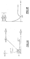
- thermodynamic model representative of the evolution of the value of the maximum of the pressure gradient in the cylinder during the main injection phase as a function of the value of the maximum of the pressure gradient during the pilot injection phase as represented by the curve of FIG. 1A representative of a thermodynamic model according to the relation: where h is the thermodynamic model representative of the evolution of the value of the maximum of the pressure gradient in the cylinder during the main injection phase as a function of the value of the maximum of the pressure gradient in the cylinder during the injection phase pilot.
- the shape of the curve shown is conventional and this curve can be parameterized by the pilot quantity q pil . Indeed, the injection of an increasing amount of pilot amount corresponds to a direction of travel of the curve according to the increasing values of the maximum of the pressure gradient during the pilot injection phase.
- thermodynamic model h It is not necessary to know explicitly this function nor the thermodynamic model h, looking for the optimal pilot injection quantity based only on qualitative considerations. For example, as it can be seen on the curve of Figure 1A, if the value of the ratio is higher at k, it is known that the pilot quantity injected is insufficient. The research of the optimal pilot quantity is then oriented towards larger pilot quantities. Similarly, if the value of the ratio is greater than k, we know that the quantity injected pilot is too important and the search is oriented accordingly to lower pilot quantities.
- relation (2) it is possible to add a feasibility constraint according to the relation: or is a characteristic function of a predetermined area of allocation of permissible values for the pair of values
- the values of these gradient maxima in a zone of values to ensure proper operation of the motor.
- the motor does not work properly and it is necessary to order it in a degraded mode.
- One way of characterizing the upper bounds of the allocation zone is to use the combustion noise note according to relation (1) where ⁇ and ⁇ are parameters determined experimentally during a listening campaign with a jury of experts and to choose for example a characteristic function of the allocation zone according to the relation: where ⁇ is a combustion noise threshold parameter determined during a listening campaign with a panel of experts.
- relations describing other characteristics of the engine as for example relations of fuel consumption, pollutant emission or other.
- combustion noise note according to the relationship (1) can be used in operation control systems of Classic diesel engines that are based on the use of combustion noise note.
- sampling may take into account linear and / or non-linear engine operation.
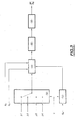
- FIG. 2 is a schematic view of an operation control system of a motor vehicle diesel engine according to the invention based on the previously described concepts.
- a diesel engine comprising means 12 for supplying fuel by multiple injections suitable for trigger a fuel injection into each cylinder according to at least one pilot injection and a main fuel injection.
- a diesel engine comprising means 12 for supplying fuel by multiple injections suitable for trigger a fuel injection into each cylinder according to at least one pilot injection and a main fuel injection.
- it may be a diesel engine with a common fuel rail cylinders by controlled injectors.
- the pilot quantity injected per cylinder and per operating point is provided by an information processing unit 14.
- This 16 command unit interrogates mapping means 18 of a storage unit 20 in according to the received speed and load information, receives in response the corresponding quantity of pilot quantity for each cylinder and sends it via an adder 22, to means 24 forming an injector mapping which deliver in response to the means 12 supply a set of information injection, relating in particular to the amount of pilot injection.
- the registration of the pilot quantities is activated by a unit 26 supervision of the information processing unit 14.
- This unit 26 of supervision sends a resetting request to the control unit 16 which starts then the determination of the optimal pilot quantity for each cylinder and for at least one operating point of the engine.
- the determination of the quantity pilot of the cylinders is then conducted sequentially, cylinder by cylinder independently of each other.
- Each cylinder is associated with a pressure sensor 28 for measuring the pressure in the cylinder's combustion chamber.
- This pressure sensor is conventionally known and can be incorporated into the combustion chamber or be non-intrusive.
- Means 30 for detecting the angle of the motor shaft are also provided. It may be for example a magnetic sensor Hall effect provided with a gear wheel associated with the motor shaft, as is known from the state of the art.
- the pressure sensors 28 and the motor shaft angle sensor 30 are connected to means 32 for determining the pressure gradients in the cylinders.
- These gradation determination means 32 are adapted to select a pressure signal coming from the pressure sensors as a function of a cylinder selection signal sent by the control unit 16 of the information processing unit 14 and to acquire a predefined portion of this selected pressure signal when the crankshaft angle of the selected cylinder is within an angle interval [ ⁇ d ⁇ f ]. This interval is delivered by the control unit 16, and ⁇ d is the acquisition start angle of the pressure signal and ⁇ f is the end of acquisition angle of the pressure signal.
- ⁇ d -30 ° and a value of ⁇ f equal to 40 ° correspond to an interval representative of the pilot injection phase and the main injection phase of the cycle of a cylinder. It is known that the pilot injection phase and the main injection phase take place in a crankshaft angle interval substantially equal to [-30 °, + 40 °].
- the means 32 for determining the pressure gradients are in further adapted to sample the selected pressure signal and derive digitally the sampled pressure signal so as to obtain a signal of sampled pressure gradient of the selected cylinder.
- the gradient pressure can be acquired analogically and then sampled.
- This pressure gradient signal is then supplied to a pilot quantity determination unit 34.
- This pilot quantity determination unit 34 comprises a calculation unit 36 which receives as input the pressure gradient and the measured crank angle to determine the maximum of the pressure gradient during the pilot injection phase and the maximum gradient during the main injection phase.
- this computing unit 36 receives as a second input the advance angle of the main injection ⁇ a of the control unit 16 and calculates the value of the maximum of the pressure gradient during the pilot injection phase ⁇ P / ⁇ pil as being the value of the maximum of the pressure gradient when the crank angle is less than ⁇ a , that is to say when this angle is in the interval [ ⁇ d ⁇ a ], and the maximum pressure gradient during the main injection phase ⁇ P / ⁇ pri as the maximum value of the pressure gradient when the crank angle is greater than or equal to ⁇ a, that is to say when this angle is in the range] ⁇ a ⁇ f ].
- the choice of the terminals is not an essential characteristic, the same results can be obtained with slightly different terminals.
- This unit also calculates, on the basis of these two maxima calculated, the ratio
- the values of the two gradient maxima of pressure as well as the value of the ratio are then provided to the control unit 16 to be stored in storage means 20 for further processing.
- the pilot quantity determination unit 34 also comprises an optimization unit 38 which receives the values of the gradient maxima of pressure and ratio, to determine an optimal value of pilot quantity. so that this value is not yet determined, this optimization unit 38 determines regularly a new pilot quantity value that is sent to the adder 22 to be added to the value from the means 18 forming mapping.
- This determination unit 34 requires certain parameters adjustment function of the operating point (speed, load) of the motor and possibly the selected cylinder. These setting parameters are read in a table 40 of the storage means means 20 by the unit 16 of command that sends them to the optimization unit 38. Operation and research an optimal pilot quantity will be described in more detail later.
- this value is provided to the control unit 16 which updates accordingly the means 18 forming cartography. Additional analysis of the results provided by unit 38 determination can be conducted to also update the parameters of the table 40 of parameters.
- FIG. 3 is an exemplary embodiment of the determination means pressure gradients in Figure 2.
- the determination means pressure gradients receive as input four pressure signals p1, p2, p3, p4 from the pressure sensors associated with the engine cylinders. These signals p1, p2, p3, p4 are supplied to controlled means 50 of signal selection adapted to select a pressure signal based of the cylinder selection signal c, delivered as described above by the control unit 16.
- These selection means 50 may for example comprise a controllable switch of conventional type.
- the means for determining the pressure gradients receive, as another input, the motor shaft angle signal ⁇ m which is supplied to a controllable adder 52 adapted to determine the crankshaft angle of the selected cylinder by the addition of a characteristic value of the selected cylinder, receiving as another input the cylinder selection signal c.
- the outputs of the selection means 50 and the adders 52 are connected to a windowing unit 54.
- This windowing unit also receives as inputs from the control unit 16 as explained above the two angle values ⁇ d and ⁇ f , respectively the acquisition start angle and the end angle of acquisition and selects the portion of the pressure signal corresponding to the crank angle included in the interval [ ⁇ d ⁇ a ].
- a digital converter / analog 55 samples this signal according to a predetermined crankshaft angle sampling period on the window determined by the selection means 50, for example 0.5 degree, to allow digital signal processing. It should be noted that sampling is not not necessarily constant. Indeed, it is possible to determine a law sample which finely samples the signal in the intervals where the signal has strong variations and samples the signal more in intervals where the signal varies little. In general, a sampling adaptive can be implemented as is known in the field of signal processing.
- the sampled signal is then supplied to a digital derivation filter 56, preferably a finite impulse response filter, which calculates a derivative digital signal of the sampled pressure signal.
- a digital derivation filter 56 preferably a finite impulse response filter, which calculates a derivative digital signal of the sampled pressure signal.
- FIG. 4 represents a flowchart of operation of pilot quantity determination means of Figure 2 and the manner in which these determining means calculate an optimal pilot quantity a cylinder, a particular operating point and a quantity of fuel injected during the predetermined main injection phase, the value of the pilot quantity injected into the other cylinders being set to a predetermined value, that stored in the means 18 forming mapping.
- the pilot amount q pil value injected at the input of the adder 22 by the optimization unit 38 is adjusted to a pre-determined initial value. If the determination is absolute, that is to say if the pilot quantity value sent from the mapping means 18 to the adder 22 is set to 0 when determining the pilot quantity, this initial value is included in FIG. the interval q max / pil. It may be for example the minimum value q min / pil or the value of the previously calculated setpoint for this cylinder.
- the initial value of q pil is set to value in the range ⁇ q min / pil - qp / pil qmax / pil - qp / pil ⁇ (it being understood that qp / pil is ⁇ q min / pil q max / pil ⁇ ) actually included in which is used as a search interval. It will be detailed thereafter a search for the absolute optimal pilot quantity for the sake of brevity of the description, without this being in any way restrictive.
- a test is carried out to know if the value of q pil is greater than q max / pil or less than q min / pil. If the result of this test is positive, an error message is generated and an engine malfunction status is diagnosed. If this result is negative, in a block 64, a cycle counter and two flags q + / pil and q - / pil are initialized to 1.
- a test is carried out to know whether the value of the cycle counter, adapted to count the cycles of the cylinder, is greater than or equal to a predetermined threshold value N + 1. If the result of this test is negative, in a block 68, the calculation unit 36 calculates and stores in the storage means 20, the maximum value of the pressure gradient ⁇ P / ⁇ pil during the pilot injection phase. and the maximum value of the pressure gradient ⁇ P / ⁇ pri during the main injection phase of the current cylinder cycle as well as the ratio of these two values.
- the cycle counter is incremented by one step an increment of one and then the output of block 68 is looped back to the input of block 66.
- a digital signal processing is then implemented by the calculation unit 36 in a block 70 on the last N values of ⁇ P / ⁇ pil of ⁇ P / ⁇ pri and of calculated.
- This digital processing may consist of noise filtering such as for example a calculation of average. It can also be estimation means using noise and / or motor models to obtain a more efficient filtering of the noise. However, calculating the average after saturation to limit the impact of very low or very high ratios corresponding to irregularities in the operation of the engine is preferred because it is robust numerically, very fast and does not use a model. Thus, as a result of this average calculation, three average values are obtained P 1 , P 2 and R corresponding respectively to the averages of the last N values of ⁇ P / ⁇ pil , ⁇ P / ⁇ pri and R.
- a first test on the value R is implemented to find out if the average value R is greater than or equal to a predetermined high ratio threshold value R_high. If the result of this test is positive, a test is implemented in a block 74 to know if the value of the flag q - / pil is equal to 0. If the result of this test on the value of q - / pil is positive, in a block 76, the pilot quantity q pil injected into the cylinder is increased by a predetermined pilot amount ⁇ q pil positive step increment, the value of the q + / pil flag is set to 0 then the block output 76 is looped back to the entrance of block 62.
- a second test on the value of R is implemented in a block 80 to know if the average value R is less than or equal to a predetermined low threshold value R_bas. If the result of this test is positive, a test is implemented in a block 82 to find out whether the value of q + / pil is equal to 0.
- a block 84 If the result of this test on the value of q + / pil is positive, in a block 84, the pilot quantity q pil injected into the cylinder is reduced by the pilot quantity increment step ⁇ q pil , the value of the flag q - / pil is set to 0 and the output of block 84 is looped back to the input of block 62.
- the interpolation of the block 78 consists in calculating by interpolation an optimum pilot quantity value when the access to the block 78 is made from the block 74 or the block 82. In fact, in these two cases, this means that one has traveled the range of acceptable values of q pil with a step that is too large, which exceeds (upwards or downwards) the optimal value without having reached it. If the access to block 78 is made from block 80, this means that a pilot quantity value has been determined which makes it possible to obtain a ratio of pressure gradient maxima close to one. In this case, a test is implemented to find out if the values P 1 , P 2 check the relation (4) of the optimization problem, ie if f ( P 1 , P 2) ⁇ 0. If the result of this test is positive then the maximum values of pressure gradient are acceptable for the operation of the engine. Otherwise, it means a malfunction of the engine which can therefore possibly switch to a degraded operating mode of the engine.
- the R_bas and R_haut values are determined to reflect the compromise noise / transmission / robustness as known in the field of engine combustion noise setting Both values frame the value k compromise set-noise / transmission set in the calibration . Their distance to this setpoint is a function of the sudden dispersion of the ratio and the robustness of the emissions and of the noise level at a small variation around this setpoint.
- the N value of the threshold for the cycle counter can be, for example chosen equal to 10, which is sufficient to satisfactorily filter the noise and the instantaneous variations of the characteristics of the combustion in the cylinder whose purpose is to determine the pilot quantity.
- this algorithm makes it possible to calculate a pilot quantity such that
- ⁇ q pil is chosen to satisfy the compromise of accuracy / search time as is commonly known in the field of optimization.
- thermodynamic model can be used, like a search by dichotomy or others. It is also possible to use an algorithm for identifying the parameters of the thermodynamic model according to relation (3) as a Kalman estimator, an estimator by maximum likelihood or other then calculate the optimal pilot amount problem of the corresponding optimization problem.
- control unit 16 can monitor continuously the value of the pressure gradient ratio and provide this value to the unit 26 of supervision.
- This supervision unit then implements a strategy of command that can for example consist of launching a new search of pilot quantity injected into the cylinders as soon as the value of the gradient ratio is not within a predetermined range of allowable values.
- the supervision unit 26 can also be adapted to trigger a resetting as soon as a time interval has elapsed since the last resetting, or as soon as a predetermined number of kilometers has been traveled since the last registration.
Landscapes
- Engineering & Computer Science (AREA)
- Chemical & Material Sciences (AREA)
- Combustion & Propulsion (AREA)
- Mechanical Engineering (AREA)
- General Engineering & Computer Science (AREA)
- Electrical Control Of Air Or Fuel Supplied To Internal-Combustion Engine (AREA)
- Combined Controls Of Internal Combustion Engines (AREA)
- Valve Device For Special Equipments (AREA)
- Testing Of Engines (AREA)
Applications Claiming Priority (2)
| Application Number | Priority Date | Filing Date | Title |
|---|---|---|---|
| FR0308351 | 2003-07-08 | ||
| FR0308351A FR2857410B1 (fr) | 2003-07-08 | 2003-07-08 | Systeme de controle du bruit de combustion d'un moteur diesel de vehicule automobile |
Publications (2)
| Publication Number | Publication Date |
|---|---|
| EP1496237A1 true EP1496237A1 (de) | 2005-01-12 |
| EP1496237B1 EP1496237B1 (de) | 2009-12-09 |
Family
ID=33443248
Family Applications (1)
| Application Number | Title | Priority Date | Filing Date |
|---|---|---|---|
| EP04291699A Expired - Lifetime EP1496237B1 (de) | 2003-07-08 | 2004-07-05 | Vorrichtung zur Verminderung des Geräusches einer selbstgezündeten Brennkraftmaschine |
Country Status (5)
| Country | Link |
|---|---|
| US (1) | US6854441B2 (de) |
| EP (1) | EP1496237B1 (de) |
| AT (1) | ATE451546T1 (de) |
| DE (1) | DE602004024476D1 (de) |
| FR (1) | FR2857410B1 (de) |
Cited By (10)
| Publication number | Priority date | Publication date | Assignee | Title |
|---|---|---|---|---|
| EP1531253A3 (de) * | 2003-11-17 | 2005-06-29 | Toyota Jidosha Kabushiki Kaisha | Steuerung einer Brennkraftmaschine abhängig vom Motorgeräusch |
| FR2886729A1 (fr) * | 2005-06-07 | 2006-12-08 | Peugeot Citroen Automobiles Sa | Procede de determination du niveau du bruit de combustion d'un moteur diesel a injection |
| FR2892464A1 (fr) * | 2005-10-24 | 2007-04-27 | Bosch Gmbh Robert | Procede et dispositif de commande d'un moteur a combustion interne |
| FR2907852A1 (fr) * | 2006-10-25 | 2008-05-02 | Renault Sas | Procede de recalage d'injecteurs d'un moteur et vehicule automobile le mettant en oeuvre |
| FR2908462A1 (fr) * | 2006-11-15 | 2008-05-16 | Renault Sas | Systeme et procede de commande d'un moteur a combustion interne |
| EP2110533A1 (de) * | 2008-04-17 | 2009-10-21 | Robert Bosch Gmbh | Elektronische Pilotsteuereinheit und Verfahren zum Ableiten optimierter Verweistabellen |
| EP2184472A1 (de) | 2008-11-10 | 2010-05-12 | Delphi Technologies Holding S.à.r.l. | Motorsteuerungssystem und Verfahren |
| FR2945319A1 (fr) * | 2009-05-11 | 2010-11-12 | Renault Sas | Systeme et procede de commande de la combustion dans un moteur a combustion interne. |
| EP1930571A3 (de) * | 2006-12-05 | 2015-04-01 | Delphi Technologies, Inc. | Verfahren zur Erfassung der Sensordaten und des Winkels eines Zylinderdrucks mit niedriger und hoher Auflösung |
| EP2884080A3 (de) * | 2013-12-02 | 2016-01-20 | Toyota Jidosha Kabushiki Kaisha | Steuerungsvorrichtung für einen Verbrennungsmotor |
Families Citing this family (18)
| Publication number | Priority date | Publication date | Assignee | Title |
|---|---|---|---|---|
| FR2886679B1 (fr) * | 2005-06-07 | 2007-10-05 | Peugeot Citroen Automobiles Sa | Systeme et procede de controle de l'injection de carburant d'un moteur diesel de vehicule automobile |
| FR2886678B1 (fr) * | 2005-06-07 | 2007-09-28 | Peugeot Citroen Automobiles Sa | Procede de reduction du bruit d'un moteur diesel a injection |
| FR2890112B1 (fr) * | 2005-08-30 | 2007-11-30 | Peugeot Citroen Automobiles Sa | Systeme de controle du fonctionnement d'un moteur diesel de vehicule automobile equipe de moyens de recirculation de gaz d'echappement |
| US7255090B2 (en) * | 2005-12-15 | 2007-08-14 | Ford Global Technologies, Llc | Compression ignition engine with pressure-based combustion control |
| US7606655B2 (en) * | 2006-09-29 | 2009-10-20 | Delphi Technologies, Inc. | Cylinder-pressure-based electronic engine controller and method |
| FR2909762A1 (fr) * | 2006-12-11 | 2008-06-13 | Renault Sas | Systeme et procede de determination du bruit de combustion dans au moins un cylindre de moteur a combustion interne |
| FR2917127B1 (fr) | 2007-06-07 | 2009-07-10 | Renault Sas | Procede de determination d'un debut de combustion dans un moteur a combustion interne |
| DE102007050302A1 (de) * | 2007-10-22 | 2009-04-23 | Robert Bosch Gmbh | Verfahren und Vorrichtung zum Ermitteln eines Zylinderdruckmerkmals |
| GB2475062B (en) * | 2009-11-03 | 2012-07-04 | Gm Global Tech Operations Inc | Method for determining an index of the fuel combustion in an engine cylinder |
| US9255543B2 (en) * | 2012-12-14 | 2016-02-09 | Hyundai Motor Company | Fuel injection amount compensating method |
| SE537313C2 (sv) * | 2013-04-25 | 2015-04-07 | Scania Cv Ab | Förfarande och system för reglering av en förbränningsmotorgenom reglering av förbränningen i en förbränningskammare under pågående förbränningscykel |
| SE537305C2 (sv) * | 2013-04-25 | 2015-03-31 | Scania Cv Ab | Förfarande och system för reglering av en förbränningsmotorgenom reglering av förbränningen i en förbränningskammare under pågående förbränningscykel |
| KR101637700B1 (ko) * | 2014-10-20 | 2016-07-07 | 현대자동차주식회사 | 엔진 연소음 피드백제어 방법 |
| US9670850B2 (en) * | 2014-11-25 | 2017-06-06 | Hyundai Motor Company | Combustion-noise controlling method for diesel engine |
| US9909522B2 (en) * | 2016-04-13 | 2018-03-06 | Jaguar Land Rover Limited | Method and apparatus for controlling an engine based on a target pressure curve |
| US9915210B2 (en) | 2016-04-13 | 2018-03-13 | Jaguar Land Rover Limited | Method and apparatus for controlling an engine based on a target pressure curve |
| CN114352418B (zh) * | 2021-11-22 | 2023-04-07 | 江铃汽车股份有限公司 | 柴油发动机启动噪声优化方法、装置、存储介质及设备 |
| CN114109636B (zh) * | 2022-01-26 | 2022-08-30 | 潍柴动力股份有限公司 | 一种改善发动机nvh性能的燃烧控制方法和发动机 |
Citations (4)
| Publication number | Priority date | Publication date | Assignee | Title |
|---|---|---|---|---|
| EP1128050A2 (de) * | 2000-02-25 | 2001-08-29 | Toyota Jidosha Kabushiki Kaisha | Kraftstoffeinspritzungssteuergerät |
| EP1219805A2 (de) * | 2000-12-19 | 2002-07-03 | Nissan Motor Co., Ltd. | Verfahren und Vorrichtung zur Steuerung der Kraftstoffeinspritzung |
| EP1316709A2 (de) * | 2001-12-01 | 2003-06-04 | Robert Bosch Gmbh | Verfahren und Vorrichtung zur Steuerung einer Brennkraftmaschine |
| EP1316704A2 (de) * | 2001-12-01 | 2003-06-04 | Robert Bosch Gmbh | Verfahren und Vorrichtung zur Steuerung einer Brennkraftmaschine |
Family Cites Families (1)
| Publication number | Priority date | Publication date | Assignee | Title |
|---|---|---|---|---|
| DE60000255T2 (de) * | 1999-09-22 | 2003-03-27 | Mitsubishi Jidosha Kogyo K.K., Tokio/Tokyo | Speicherkraftstoffeinspritzvorrichtung |
-
2003
- 2003-07-08 FR FR0308351A patent/FR2857410B1/fr not_active Expired - Fee Related
-
2004
- 2004-07-05 EP EP04291699A patent/EP1496237B1/de not_active Expired - Lifetime
- 2004-07-05 DE DE602004024476T patent/DE602004024476D1/de not_active Expired - Lifetime
- 2004-07-05 AT AT04291699T patent/ATE451546T1/de not_active IP Right Cessation
- 2004-07-07 US US10/885,025 patent/US6854441B2/en not_active Expired - Fee Related
Patent Citations (4)
| Publication number | Priority date | Publication date | Assignee | Title |
|---|---|---|---|---|
| EP1128050A2 (de) * | 2000-02-25 | 2001-08-29 | Toyota Jidosha Kabushiki Kaisha | Kraftstoffeinspritzungssteuergerät |
| EP1219805A2 (de) * | 2000-12-19 | 2002-07-03 | Nissan Motor Co., Ltd. | Verfahren und Vorrichtung zur Steuerung der Kraftstoffeinspritzung |
| EP1316709A2 (de) * | 2001-12-01 | 2003-06-04 | Robert Bosch Gmbh | Verfahren und Vorrichtung zur Steuerung einer Brennkraftmaschine |
| EP1316704A2 (de) * | 2001-12-01 | 2003-06-04 | Robert Bosch Gmbh | Verfahren und Vorrichtung zur Steuerung einer Brennkraftmaschine |
Cited By (14)
| Publication number | Priority date | Publication date | Assignee | Title |
|---|---|---|---|---|
| EP1531253A3 (de) * | 2003-11-17 | 2005-06-29 | Toyota Jidosha Kabushiki Kaisha | Steuerung einer Brennkraftmaschine abhängig vom Motorgeräusch |
| FR2886729A1 (fr) * | 2005-06-07 | 2006-12-08 | Peugeot Citroen Automobiles Sa | Procede de determination du niveau du bruit de combustion d'un moteur diesel a injection |
| WO2006131673A1 (fr) * | 2005-06-07 | 2006-12-14 | Peugeot Citroën Automobiles Sa. | Procede de determination du niveau de bruit de combustion d'un moteur diesel a injection |
| FR2892464A1 (fr) * | 2005-10-24 | 2007-04-27 | Bosch Gmbh Robert | Procede et dispositif de commande d'un moteur a combustion interne |
| FR2907852A1 (fr) * | 2006-10-25 | 2008-05-02 | Renault Sas | Procede de recalage d'injecteurs d'un moteur et vehicule automobile le mettant en oeuvre |
| WO2008050033A3 (fr) * | 2006-10-25 | 2008-06-19 | Renault Sa | Procede de recalage d'injecteurs d'un moteur et vehicule automobile le mettant en oeuvre |
| EP1923558A1 (de) * | 2006-11-15 | 2008-05-21 | Renault s.a.s. | Steuersystem und -verfahren eines Verbrennungsmotors |
| FR2908462A1 (fr) * | 2006-11-15 | 2008-05-16 | Renault Sas | Systeme et procede de commande d'un moteur a combustion interne |
| EP1930571A3 (de) * | 2006-12-05 | 2015-04-01 | Delphi Technologies, Inc. | Verfahren zur Erfassung der Sensordaten und des Winkels eines Zylinderdrucks mit niedriger und hoher Auflösung |
| EP2110533A1 (de) * | 2008-04-17 | 2009-10-21 | Robert Bosch Gmbh | Elektronische Pilotsteuereinheit und Verfahren zum Ableiten optimierter Verweistabellen |
| EP2184472A1 (de) | 2008-11-10 | 2010-05-12 | Delphi Technologies Holding S.à.r.l. | Motorsteuerungssystem und Verfahren |
| FR2945319A1 (fr) * | 2009-05-11 | 2010-11-12 | Renault Sas | Systeme et procede de commande de la combustion dans un moteur a combustion interne. |
| EP2256322A1 (de) * | 2009-05-11 | 2010-12-01 | Renault S.A.S. | Einfluss der NOx Regelung auf die Motorgeräuschregelung in einer Brennkraftmaschine |
| EP2884080A3 (de) * | 2013-12-02 | 2016-01-20 | Toyota Jidosha Kabushiki Kaisha | Steuerungsvorrichtung für einen Verbrennungsmotor |
Also Published As
| Publication number | Publication date |
|---|---|
| US20050005902A1 (en) | 2005-01-13 |
| EP1496237B1 (de) | 2009-12-09 |
| FR2857410A1 (fr) | 2005-01-14 |
| US6854441B2 (en) | 2005-02-15 |
| DE602004024476D1 (de) | 2010-01-21 |
| FR2857410B1 (fr) | 2005-10-14 |
| ATE451546T1 (de) | 2009-12-15 |
Similar Documents
| Publication | Publication Date | Title |
|---|---|---|
| EP1496237B1 (de) | Vorrichtung zur Verminderung des Geräusches einer selbstgezündeten Brennkraftmaschine | |
| EP1644627B1 (de) | Verfahren zur echtzeitbestimmung einer kraftstoffeinspritzungsströmungscharakteristik | |
| FR2901847A1 (fr) | Dispositif et procede de commande d'injection de carburant | |
| FR2890114A1 (fr) | Procede de gestion d'un moteur a combustion interne | |
| EP1705355A1 (de) | Verfahren zur Bestimmung von Parametern eines Einspritzsystems | |
| FR2883332A1 (fr) | Procede et dispositif de gestion d'un moteur a combustion interne | |
| WO2014131508A1 (fr) | Procede de pilotage d'un injecteur piezoelectrique de carburant d'un moteur a combustion interne de vehicule, comportant une etape de polarisation de l'actionneur piezoelectrique | |
| EP0686762A1 (de) | Verfahren und Vorrichtung zur Bestimmung von spezifischen Parametern von Einspritzventilen eines Verbrennungsmotors insbesondere für Dieselmotoren mit Voreinspritzung | |
| EP1058781B1 (de) | Verfahren und einrichtung zum schnellen selbstanpassen des luft/kraftstoffverhältnisses in einer brennkraftmaschine | |
| WO2008084170A2 (fr) | Procede de regulation d'un moteur a combustion interne | |
| FR2859763A1 (fr) | Procede et dispositif de gestion d'un moteur a combustion interne | |
| EP3201443B1 (de) | Fahrzeugverbrennungsmotor mit verbesserter gemischstärkeregelung | |
| EP1862659A1 (de) | Verfahren und Vorrichtung zur Korrektur des Durchsatzes der Voreinspritzung von Treibstoff in einen Dieseldirekteinspritzmotor des Common-Rail-Typs und Motor, der eine solche Vorrichtung umfasst | |
| FR3088965A1 (fr) | Procede de correction de commande d’un moteur thermique | |
| FR2851013A1 (fr) | Procede et dispositif de correction adaptative de l'onde de choc dans un systeme d'injection a haute pression d'un vehicule automobile pendant son fonctionnement | |
| FR2718191A1 (fr) | Procédé et dispositif de suppression des oscillations longitudinales d'un véhicule automobile à moteur. | |
| EP1400679B1 (de) | Steuereinrichtung um einen Kraftfahrzeug-Dieselmotor zu betrieben | |
| EP1760295B1 (de) | Regelvorrichtung für eine Diesel-Brennkraftmaschine mit Abgasrückführung | |
| EP3215727B1 (de) | Verfahren zur vorhersage einer gaseinlassseitigen drosselklappe für die steuerung einer brennkraftmaschine | |
| EP2123889A1 (de) | Verfahren für Verbrennungsmotor und Gerät für die Durchführung der genannten Verfahren | |
| WO2023072565A1 (fr) | Procédé d'estimation de la pression atmosphérique pour un moteur à combustion interne | |
| EP1597468A1 (de) | Verfahren zur bestimmung der verstärkung eines kraftstoffeinspritzventils | |
| WO2023242088A1 (fr) | Système et procédé de détermination d'une grandeur dans un véhicule automobile | |
| EP1512861A1 (de) | Vorrichtung zur Überwachung wenigstens eines Steuerparameters einer Brennkraftmaschine | |
| FR2934642A1 (fr) | Procede et systeme de correction du temps mort d'injecteurs pour un moteur a combustion interne |
Legal Events
| Date | Code | Title | Description |
|---|---|---|---|
| PUAI | Public reference made under article 153(3) epc to a published international application that has entered the european phase |
Free format text: ORIGINAL CODE: 0009012 |
|
| AK | Designated contracting states |
Kind code of ref document: A1 Designated state(s): AT BE BG CH CY CZ DE DK EE ES FI FR GB GR HU IE IT LI LU MC NL PL PT RO SE SI SK TR |
|
| AX | Request for extension of the european patent |
Extension state: AL HR LT LV MK |
|
| 17P | Request for examination filed |
Effective date: 20050310 |
|
| AKX | Designation fees paid |
Designated state(s): AT BE BG CH CY CZ DE DK EE ES FI FR GB GR HU IE IT LI LU MC NL PL PT RO SE SI SK TR |
|
| GRAP | Despatch of communication of intention to grant a patent |
Free format text: ORIGINAL CODE: EPIDOSNIGR1 |
|
| GRAS | Grant fee paid |
Free format text: ORIGINAL CODE: EPIDOSNIGR3 |
|
| GRAA | (expected) grant |
Free format text: ORIGINAL CODE: 0009210 |
|
| AK | Designated contracting states |
Kind code of ref document: B1 Designated state(s): AT BE BG CH CY CZ DE DK EE ES FI FR GB GR HU IE IT LI LU MC NL PL PT RO SE SI SK TR |
|
| REG | Reference to a national code |
Ref country code: GB Ref legal event code: FG4D Free format text: NOT ENGLISH |
|
| REG | Reference to a national code |
Ref country code: CH Ref legal event code: EP |
|
| REG | Reference to a national code |
Ref country code: IE Ref legal event code: FG4D |
|
| REF | Corresponds to: |
Ref document number: 602004024476 Country of ref document: DE Date of ref document: 20100121 Kind code of ref document: P |
|
| REG | Reference to a national code |
Ref country code: NL Ref legal event code: VDEP Effective date: 20091209 |
|
| PG25 | Lapsed in a contracting state [announced via postgrant information from national office to epo] |
Ref country code: SE Free format text: LAPSE BECAUSE OF FAILURE TO SUBMIT A TRANSLATION OF THE DESCRIPTION OR TO PAY THE FEE WITHIN THE PRESCRIBED TIME-LIMIT Effective date: 20091209 Ref country code: FI Free format text: LAPSE BECAUSE OF FAILURE TO SUBMIT A TRANSLATION OF THE DESCRIPTION OR TO PAY THE FEE WITHIN THE PRESCRIBED TIME-LIMIT Effective date: 20091209 |
|
| PG25 | Lapsed in a contracting state [announced via postgrant information from national office to epo] |
Ref country code: PL Free format text: LAPSE BECAUSE OF FAILURE TO SUBMIT A TRANSLATION OF THE DESCRIPTION OR TO PAY THE FEE WITHIN THE PRESCRIBED TIME-LIMIT Effective date: 20091209 Ref country code: SI Free format text: LAPSE BECAUSE OF FAILURE TO SUBMIT A TRANSLATION OF THE DESCRIPTION OR TO PAY THE FEE WITHIN THE PRESCRIBED TIME-LIMIT Effective date: 20091209 |
|
| PG25 | Lapsed in a contracting state [announced via postgrant information from national office to epo] |
Ref country code: AT Free format text: LAPSE BECAUSE OF FAILURE TO SUBMIT A TRANSLATION OF THE DESCRIPTION OR TO PAY THE FEE WITHIN THE PRESCRIBED TIME-LIMIT Effective date: 20091209 |
|
| REG | Reference to a national code |
Ref country code: IE Ref legal event code: FD4D |
|
| PG25 | Lapsed in a contracting state [announced via postgrant information from national office to epo] |
Ref country code: RO Free format text: LAPSE BECAUSE OF FAILURE TO SUBMIT A TRANSLATION OF THE DESCRIPTION OR TO PAY THE FEE WITHIN THE PRESCRIBED TIME-LIMIT Effective date: 20091209 Ref country code: NL Free format text: LAPSE BECAUSE OF FAILURE TO SUBMIT A TRANSLATION OF THE DESCRIPTION OR TO PAY THE FEE WITHIN THE PRESCRIBED TIME-LIMIT Effective date: 20091209 Ref country code: ES Free format text: LAPSE BECAUSE OF FAILURE TO SUBMIT A TRANSLATION OF THE DESCRIPTION OR TO PAY THE FEE WITHIN THE PRESCRIBED TIME-LIMIT Effective date: 20100320 Ref country code: PT Free format text: LAPSE BECAUSE OF FAILURE TO SUBMIT A TRANSLATION OF THE DESCRIPTION OR TO PAY THE FEE WITHIN THE PRESCRIBED TIME-LIMIT Effective date: 20100409 Ref country code: BG Free format text: LAPSE BECAUSE OF FAILURE TO SUBMIT A TRANSLATION OF THE DESCRIPTION OR TO PAY THE FEE WITHIN THE PRESCRIBED TIME-LIMIT Effective date: 20100309 Ref country code: EE Free format text: LAPSE BECAUSE OF FAILURE TO SUBMIT A TRANSLATION OF THE DESCRIPTION OR TO PAY THE FEE WITHIN THE PRESCRIBED TIME-LIMIT Effective date: 20091209 Ref country code: IE Free format text: LAPSE BECAUSE OF FAILURE TO SUBMIT A TRANSLATION OF THE DESCRIPTION OR TO PAY THE FEE WITHIN THE PRESCRIBED TIME-LIMIT Effective date: 20091209 |
|
| PG25 | Lapsed in a contracting state [announced via postgrant information from national office to epo] |
Ref country code: CZ Free format text: LAPSE BECAUSE OF FAILURE TO SUBMIT A TRANSLATION OF THE DESCRIPTION OR TO PAY THE FEE WITHIN THE PRESCRIBED TIME-LIMIT Effective date: 20091209 Ref country code: SK Free format text: LAPSE BECAUSE OF FAILURE TO SUBMIT A TRANSLATION OF THE DESCRIPTION OR TO PAY THE FEE WITHIN THE PRESCRIBED TIME-LIMIT Effective date: 20091209 |
|
| PLBE | No opposition filed within time limit |
Free format text: ORIGINAL CODE: 0009261 |
|
| STAA | Information on the status of an ep patent application or granted ep patent |
Free format text: STATUS: NO OPPOSITION FILED WITHIN TIME LIMIT |
|
| PG25 | Lapsed in a contracting state [announced via postgrant information from national office to epo] |
Ref country code: GR Free format text: LAPSE BECAUSE OF FAILURE TO SUBMIT A TRANSLATION OF THE DESCRIPTION OR TO PAY THE FEE WITHIN THE PRESCRIBED TIME-LIMIT Effective date: 20100310 Ref country code: CY Free format text: LAPSE BECAUSE OF FAILURE TO SUBMIT A TRANSLATION OF THE DESCRIPTION OR TO PAY THE FEE WITHIN THE PRESCRIBED TIME-LIMIT Effective date: 20091209 |
|
| 26N | No opposition filed |
Effective date: 20100910 |
|
| PGFP | Annual fee paid to national office [announced via postgrant information from national office to epo] |
Ref country code: DE Payment date: 20100706 Year of fee payment: 7 |
|
| BERE | Be: lapsed |
Owner name: PEUGEOT CITROEN AUTOMOBILES S.A. Effective date: 20100731 Owner name: DELPHI TECHNOLOGIES, INC. Effective date: 20100731 |
|
| PG25 | Lapsed in a contracting state [announced via postgrant information from national office to epo] |
Ref country code: DK Free format text: LAPSE BECAUSE OF FAILURE TO SUBMIT A TRANSLATION OF THE DESCRIPTION OR TO PAY THE FEE WITHIN THE PRESCRIBED TIME-LIMIT Effective date: 20091209 |
|
| PG25 | Lapsed in a contracting state [announced via postgrant information from national office to epo] |
Ref country code: MC Free format text: LAPSE BECAUSE OF NON-PAYMENT OF DUE FEES Effective date: 20100731 |
|
| REG | Reference to a national code |
Ref country code: CH Ref legal event code: PL |
|
| PG25 | Lapsed in a contracting state [announced via postgrant information from national office to epo] |
Ref country code: CH Free format text: LAPSE BECAUSE OF NON-PAYMENT OF DUE FEES Effective date: 20100731 Ref country code: LI Free format text: LAPSE BECAUSE OF NON-PAYMENT OF DUE FEES Effective date: 20100731 |
|
| PG25 | Lapsed in a contracting state [announced via postgrant information from national office to epo] |
Ref country code: BE Free format text: LAPSE BECAUSE OF NON-PAYMENT OF DUE FEES Effective date: 20100731 |
|
| PGFP | Annual fee paid to national office [announced via postgrant information from national office to epo] |
Ref country code: IT Payment date: 20110618 Year of fee payment: 8 |
|
| PGFP | Annual fee paid to national office [announced via postgrant information from national office to epo] |
Ref country code: GB Payment date: 20110701 Year of fee payment: 8 |
|
| PG25 | Lapsed in a contracting state [announced via postgrant information from national office to epo] |
Ref country code: DE Free format text: LAPSE BECAUSE OF NON-PAYMENT OF DUE FEES Effective date: 20120201 |
|
| REG | Reference to a national code |
Ref country code: DE Ref legal event code: R119 Ref document number: 602004024476 Country of ref document: DE Effective date: 20120201 |
|
| PG25 | Lapsed in a contracting state [announced via postgrant information from national office to epo] |
Ref country code: HU Free format text: LAPSE BECAUSE OF FAILURE TO SUBMIT A TRANSLATION OF THE DESCRIPTION OR TO PAY THE FEE WITHIN THE PRESCRIBED TIME-LIMIT Effective date: 20100610 Ref country code: LU Free format text: LAPSE BECAUSE OF NON-PAYMENT OF DUE FEES Effective date: 20100705 |
|
| PG25 | Lapsed in a contracting state [announced via postgrant information from national office to epo] |
Ref country code: TR Free format text: LAPSE BECAUSE OF FAILURE TO SUBMIT A TRANSLATION OF THE DESCRIPTION OR TO PAY THE FEE WITHIN THE PRESCRIBED TIME-LIMIT Effective date: 20091209 |
|
| PGFP | Annual fee paid to national office [announced via postgrant information from national office to epo] |
Ref country code: FR Payment date: 20120806 Year of fee payment: 9 |
|
| GBPC | Gb: european patent ceased through non-payment of renewal fee |
Effective date: 20120705 |
|
| PG25 | Lapsed in a contracting state [announced via postgrant information from national office to epo] |
Ref country code: GB Free format text: LAPSE BECAUSE OF NON-PAYMENT OF DUE FEES Effective date: 20120705 |
|
| PG25 | Lapsed in a contracting state [announced via postgrant information from national office to epo] |
Ref country code: IT Free format text: LAPSE BECAUSE OF NON-PAYMENT OF DUE FEES Effective date: 20120705 |
|
| REG | Reference to a national code |
Ref country code: FR Ref legal event code: ST Effective date: 20140331 |
|
| PG25 | Lapsed in a contracting state [announced via postgrant information from national office to epo] |
Ref country code: FR Free format text: LAPSE BECAUSE OF NON-PAYMENT OF DUE FEES Effective date: 20130731 |