EP1496250A2 - Wasserturbine zur Erhöhung von in Wasser gelöstem Sauerstoff - Google Patents
Wasserturbine zur Erhöhung von in Wasser gelöstem Sauerstoff Download PDFInfo
- Publication number
- EP1496250A2 EP1496250A2 EP04254061A EP04254061A EP1496250A2 EP 1496250 A2 EP1496250 A2 EP 1496250A2 EP 04254061 A EP04254061 A EP 04254061A EP 04254061 A EP04254061 A EP 04254061A EP 1496250 A2 EP1496250 A2 EP 1496250A2
- Authority
- EP
- European Patent Office
- Prior art keywords
- band
- chamber
- water
- turbine
- hydraulic turbine
- Prior art date
- Legal status (The legal status is an assumption and is not a legal conclusion. Google has not performed a legal analysis and makes no representation as to the accuracy of the status listed.)
- Withdrawn
Links
- XLYOFNOQVPJJNP-UHFFFAOYSA-N water Substances O XLYOFNOQVPJJNP-UHFFFAOYSA-N 0.000 title claims abstract description 91
- QVGXLLKOCUKJST-UHFFFAOYSA-N atomic oxygen Chemical compound [O] QVGXLLKOCUKJST-UHFFFAOYSA-N 0.000 title claims abstract description 57
- 239000001301 oxygen Substances 0.000 title claims abstract description 57
- 229910052760 oxygen Inorganic materials 0.000 title claims abstract description 57
- 230000002708 enhancing effect Effects 0.000 title 1
- 239000007789 gas Substances 0.000 claims abstract description 46
- 239000012080 ambient air Substances 0.000 claims description 19
- 238000011144 upstream manufacturing Methods 0.000 claims description 9
- 239000012530 fluid Substances 0.000 claims description 3
- 239000003570 air Substances 0.000 description 9
- 238000009434 installation Methods 0.000 description 6
- 239000000203 mixture Substances 0.000 description 3
- 230000000694 effects Effects 0.000 description 2
- 230000007613 environmental effect Effects 0.000 description 2
- 238000004519 manufacturing process Methods 0.000 description 1
- 238000013517 stratification Methods 0.000 description 1
- 238000013022 venting Methods 0.000 description 1
Images


Classifications
-
- F—MECHANICAL ENGINEERING; LIGHTING; HEATING; WEAPONS; BLASTING
- F03—MACHINES OR ENGINES FOR LIQUIDS; WIND, SPRING, OR WEIGHT MOTORS; PRODUCING MECHANICAL POWER OR A REACTIVE PROPULSIVE THRUST, NOT OTHERWISE PROVIDED FOR
- F03B—MACHINES OR ENGINES FOR LIQUIDS
- F03B3/00—Machines or engines of reaction type; Parts or details peculiar thereto
- F03B3/12—Blades; Blade-carrying rotors
- F03B3/125—Rotors for radial flow at high-pressure side and axial flow at low-pressure side, e.g. for Francis-type turbines
-
- F—MECHANICAL ENGINEERING; LIGHTING; HEATING; WEAPONS; BLASTING
- F03—MACHINES OR ENGINES FOR LIQUIDS; WIND, SPRING, OR WEIGHT MOTORS; PRODUCING MECHANICAL POWER OR A REACTIVE PROPULSIVE THRUST, NOT OTHERWISE PROVIDED FOR
- F03B—MACHINES OR ENGINES FOR LIQUIDS
- F03B11/00—Parts or details not provided for in, or of interest apart from, the preceding groups, e.g. wear-protection couplings, between turbine and generator
- F03B11/002—Injecting air or other fluid
-
- Y—GENERAL TAGGING OF NEW TECHNOLOGICAL DEVELOPMENTS; GENERAL TAGGING OF CROSS-SECTIONAL TECHNOLOGIES SPANNING OVER SEVERAL SECTIONS OF THE IPC; TECHNICAL SUBJECTS COVERED BY FORMER USPC CROSS-REFERENCE ART COLLECTIONS [XRACs] AND DIGESTS
- Y02—TECHNOLOGIES OR APPLICATIONS FOR MITIGATION OR ADAPTATION AGAINST CLIMATE CHANGE
- Y02E—REDUCTION OF GREENHOUSE GAS [GHG] EMISSIONS, RELATED TO ENERGY GENERATION, TRANSMISSION OR DISTRIBUTION
- Y02E10/00—Energy generation through renewable energy sources
- Y02E10/20—Hydro energy
Definitions
- the present invention relates to a hydraulic turbine and, in particular, to a turbine adapted to increase the dissolved oxygen content of water flowing through the turbine.
- the oxygen levels of water discharged from hydraulic turbines used in hydroelectric installations have been known to provide an environmental problem due to the discharged water having relatively low levels of dissolved oxygen.
- the problem is more predominant in the summer months.
- thermal stratification of water in an upstream water reservoir creates warmer water near the surface having relatively high dissolved oxygen and colder water near the bottom of the reservoir having relatively lower dissolved oxygen.
- the water utilized by the turbines is usually taken from the bottom of the reservoir, this water presents a potentially environmental hazard when discharged downstream by the turbines.
- the turbine has a rotatably mounted runner having a band, a stationary discharge ring and a seal between the band and the discharge ring. While the band seal limits water leakage into a band mixing chamber formed between the runner band and the stationaly discharge ring, the mixing chamber is substantially flooded with water during turbine operation. An oxygen containing gas is injected into the chamber through a gas admission aperture located near the seal. The mixing chamber is configured to promote mixing of the oxygen containing gas and water leaking into the chamber. The gas and water mixture is then discharged through an outlet port between the discharge ring and the runner band. However, by having the chamber substantially flooded with water, the amount of oxygen introduced into the water flowing through the turbine is limited.
- the present invention relates to a hydraulic turbine adapted to introduce oxygen into the water flowing through the water passageway of the turbine. This is accomplished by having a circumferential chamber positioned between a stationary discharge ring of the turbine and a rotating band of the turbine runner.
- the chamber has a gas admission aperture for receiving an oxygen containing gas into the chamber.
- the band has a plurality of spaced apart vanes that provide chamber outlet passageways that extend between the vanes. The vanes are configured to rotate with the band and draw the oxygen containing gas and any water leaked into the chamber through the outlet passageways and into the water passageway of the turbine.
- the vanes when rotating with the band, act as fan blades that draw or induce the flow of oxygen containing gas from the chamber into the water turbine passageway thereby increasing the dissolved oxygen content of the water flowing through the turbine.
- This inducement of air flow out of the chamber permits for large air content in the mixture of water and air in the chamber and thereby improves the content of air or oxygen introduced into the water passageway.
- the circumferential chamber is formed between the rotating band and the stationary discharge ring and extends around the rotating band.
- the rotating band may be configured or shaped with a recess in its outer wall to enhance the size of the chamber.
- the stationary discharge ring may be also shaped along its outer confronting wall to the band in a manner that the chamber is enlarged to increase the volume of oxygen containing gas received within the chamber.
- the turbine has an upper seal positioned between the band and the stationary discharge ring to limit water leakage into the circumferential chamber.
- the seal is configured such that the circumferential chamber remains substantially unflooded during turbine operation.
- substantially unflooded it is meant that the volume of water in the chamber is less than 50% of the volume of the chamber, and preferably the volume of water is in the range of about 20% to 30% of the volume of the chamber.
- the top seal is a tighter seal than the lower seal due to the pressure differential adjacent the top seal being higher than that adjacent the lower seal. This further induces any oxygen containing gas and water mixture contained within the chamber to flow towards the bottom seal and, in particular, flow out through the plurality of outlet passageways in the band.
- the downstream end portion of the band has a circumferential band portion that surrounds the vanes whereby the outlet passageways of the band are contained within and extend through the lower band portion.
- the lower seal is disposed between the circumferential band portion and the stationary ring portion.
- the lower seal may be positioned directly adjacent to the vanes and the outlet passageways extend between the band and the lower seal.
- the turbine further includes a draft tube downstream of the turbine runner and the band.
- the draft tube has an inner diameter wall adjacent the band.
- the outlet passageways of the downstream band portion adjacent the water passageway are positioned inwardly of the inner wall of the draft tube adjacent the band. This permits for oxygen containing gas to enter the water passageway with no restrictions from the top of the draft tube.
- the outlet passageways pass through the downstream end portion of the band and have inlet openings and discharge openings. The inlet openings communicate with the chamber and the discharge openings communicate with the water passageway.
- a hydraulic turbine adapted to introduce oxygen into water flowing through a water passageway of a turbine.
- the turbine comprises a rotatably mounted runner having a crown, a band substantially concentric with the crown, and a plurality of runner blades extending between the crown and the band.
- the band has an upstream end portion and a downstream end portion.
- the turbine has a stationary discharge ring substantially concentric with the band and spaced outwardly therefrom.
- the turbine has a circumferential chamber formed between the band and the stationary discharge ring.
- the chamber has a gas admission aperture for receiving an oxygen containing gas into the chamber.
- the turbine has an upper seal positioned adjacent the upstream end portion of the band between the band and the stationary discharge ring to limit water leakage into a circumferential chamber.
- the turbine has a lower seal positioned adjacent the downstream end portion of the band between the band and the stationary discharge ring to reduce undesirable recirculation of water from downstream back to the chamber between the band and the stationary discharge ring.
- the downstream end portion of the band has a plurality of spaced apart vanes providing chamber outlet passageways between the vanes in fluid communication with the circumferential chamber and the water passageway. The vanes are configured to rotate with the band and draw the oxygen containing gas and water from the chamber, through the outlet passageways and into the water passageway.
- the present invention relates to a hydraulic turbine and, in particular, to a turbine adapted to increase the dissolved oxygen content of water discharged from the turbine.
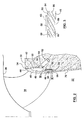
- a turbine installation 10 is illustrated for use in the generation of hydroelectricity.
- the installation 10 has a water passageway 12. Water flows from an inlet 14 of passageway 12 to an outlet 16 located at a lower elevation.
- the water passageway 12 passes through a Francis turbine 18 having a runner 20 and a draft tube 22.
- the runner 20 is secured by bolts 24 to a shaft 26 transmitting energy to a generator (not shown).
- the turbine 18 is mounted in a stationary casing 28 having a head cover 30 and a bottom stationary discharge ring 32.
- the head cover 30, discharge ring 32 and draft tube 22 are embedded in concrete foundation 34.
- Runner 20 is rotatably mounted in casing 28 and has a crown 36 and a plurality of circumferentially spaced runner blades 38 extending therefrom to an enclosing band 40.
- Band 40 is concentric with crown 36.
- installation 10 includes other components such as, for example, stay vanes and wicket gates which are not shown.
- a circumferential chamber 42 is located between the band 40 and the stationary discharge ring 32. Chamber 42 extends around the outside of band 40.
- the band 40 is shown to have an upstream end portion 44 and a downstream end portion 46.
- the band 40 further has an outer wall 48 that is configured with a recess to increase the volume of chamber 42.
- the chamber 42 has a gas admission aperture 50 connected to a gas supply line 52 through which a supply of oxygen containing gas or ambient air may pass either under pressure or at ambient pressure into chamber 42.
- the oxygen containing gas is air.
- an upper seal 54 is positioned adjacent the upstream end portion 44 of the band 40 between the band 40 and the stationary discharge ring 32.
- This seal 54 acts to limit water leakage into the circumferential chamber 42.
- the seal is effective such that the circumferential chamber remains substantially unflooded.
- substantially unflooded it is meant that at least 50 per cent or more of the chamber is unflooded with water at any given time during turbine operation and preferably the volume of water is in the range of about 20% to 30% of the volume of the chamber.
- the seal 54 works such that 70% to 80% of the chamber 42 is unflooded with water at any given time.
- a lower seal 56 is positioned adjacent the downstream end portion 46 of band 40 between the band 40 and the stationary discharge ring 32. This seal is provided to reduce the undesirable escape of oxygen containing gas and water from the chamber between the band 40 and the stationary discharge ring 32. It should be understood that the tightness or the effectiveness of seal 56 is chosen to be less effective from a seal perspective than the seal 54 such that there is a natural tendency for any oxygen or gas contained in the chamber 42 to flow towards the seal 56 away from seal 54.
- the downstream end portion 46 of band 40 has a plurality of outlet passageways 58 (see Figure 3) spaced between vanes 60. Vanes 60 extend radially outward of the downstream end portion 46 of the band 40 and are sloped to provide a fan effect. In the embodiment shown in Figure 2, the vanes 60 extend into and contact a circumferential band portion 62. In this way, the passageways 58 are self contained within the downstream end portion 46 of the band 40.
- each of the outlet passageways 58 of the downstream end portion 46 of the band 40 has an inlet opening 64 which communicates with the chamber 42 and also has a discharge opening 66 which communicates with the water passageway 12.
- the vanes 60 act as fan blades to draw oxygen containing gas and water from chamber 42 in through inlet openings 64 through passageways 58 between the vanes 60, and out the discharge openings 66 into the water passageway 12.
- the outlet passageways 58 extend in the downstream direction associated with the flow of water through the water passageway 12.
- the passageways 58 further extend radially inwardly of the band 40 such that the discharge openings 66 are located within or radially inward of the inner wall 70 of the draft tube 22. This results in the oxygen containing gas being discharged into the water passageway 12 unencumbered by the upper end of the draft tube 22.
- the size and number of the vanes 60, and the sloping orientation of the vanes 60 as shown in Figure 3, are chosen to provide the desired fan effect to suction or draw the oxygen containing gas and water from chamber 42 at a rate sufficient to provide sufficient dissolved oxygen content in the water passageway 12.
- the self containing of the outlet passageways 58 and vanes 60 within the lower end portion 46 of the band 40 provides a self venting feature through the band 40.
- FIG. 4 an alternative embodiment is shown wherein the downstream end portion 46 of the band 40 does not have a circumferential band portion 62 as shown in Figure 2.
- the lower seal 56 is mounted to the discharge ring 32 so that the seal 56 is directly adjacent the vanes 60. It should be understood that there may be a slight gap between the vanes 60 and the seal 56.
- the rotation of the band 40 result in the rotation of the vanes 60 so as to draw water and oxygen from the chamber 42 through the outlet passageways 56 located between the vanes 60.
- the radial outer boundary of the outlet passageways 58 is defined by the lower seal 56 and not the circumferential band portion 62 as shown in Figure 2.
Landscapes
- Engineering & Computer Science (AREA)
- Chemical & Material Sciences (AREA)
- Combustion & Propulsion (AREA)
- Mechanical Engineering (AREA)
- General Engineering & Computer Science (AREA)
- Hydraulic Turbines (AREA)
- Aeration Devices For Treatment Of Activated Polluted Sludge (AREA)
Applications Claiming Priority (2)
| Application Number | Priority Date | Filing Date | Title |
|---|---|---|---|
| US615261 | 2003-07-09 | ||
| US10/615,261 US6854958B2 (en) | 2003-07-09 | 2003-07-09 | Hydraulic turbine with enhanced dissolved oxygen |
Publications (2)
| Publication Number | Publication Date |
|---|---|
| EP1496250A2 true EP1496250A2 (de) | 2005-01-12 |
| EP1496250A3 EP1496250A3 (de) | 2011-04-27 |
Family
ID=33452659
Family Applications (1)
| Application Number | Title | Priority Date | Filing Date |
|---|---|---|---|
| EP04254061A Withdrawn EP1496250A3 (de) | 2003-07-09 | 2004-07-07 | Wasserturbine zur Erhöhung von in Wasser gelöstem Sauerstoff |
Country Status (3)
| Country | Link |
|---|---|
| US (1) | US6854958B2 (de) |
| EP (1) | EP1496250A3 (de) |
| CA (1) | CA2472540C (de) |
Families Citing this family (6)
| Publication number | Priority date | Publication date | Assignee | Title |
|---|---|---|---|---|
| US7070388B2 (en) * | 2004-02-26 | 2006-07-04 | United Technologies Corporation | Inducer with shrouded rotor for high speed applications |
| US7044452B2 (en) * | 2004-04-30 | 2006-05-16 | General Electric Canada | Hydraulic turbine draft tube deflector with enhanced dissolved oxygen |
| US8360743B2 (en) | 2009-01-23 | 2013-01-29 | Randy Walters | Rotary pressure production device |
| WO2018147866A1 (en) | 2017-02-10 | 2018-08-16 | Daramic, Llc | Improved separators with fibrous mat, lead acid batteries, and methods and systems associated therewith |
| WO2019179742A1 (en) * | 2018-03-22 | 2019-09-26 | Voith Patent Gmbh | Runner for a hydraulic turbine or pump and method of manufacturing |
| CN111264458B (zh) * | 2020-03-21 | 2024-06-21 | 郑卫兵 | 一种增氧机叶轮 |
Family Cites Families (16)
| Publication number | Priority date | Publication date | Assignee | Title |
|---|---|---|---|---|
| US2851289A (en) * | 1957-03-22 | 1958-09-09 | Thiokol Chemical Corp | Recirculation seal with plastic wear ring for hydraulic apparatus |
| US3174719A (en) * | 1962-06-12 | 1965-03-23 | Dominion Eng Works Ltd | Francis turbines and centrifugal pumps |
| US3172640A (en) * | 1963-04-08 | 1965-03-09 | Dominion Eng Works Ltd | Dry band francis turbines |
| US3360238A (en) * | 1967-02-13 | 1967-12-26 | Dominion Eng Works Ltd | Shroud seal for hydraulic machines |
| CA901428A (en) * | 1970-07-29 | 1972-05-30 | Dominion Engineering Works Limited | Hydraulic machine crown aeration |
| CA1058055A (en) * | 1976-11-26 | 1979-07-10 | Dominion Engineering Works Limited | Draft tube aeration with eductor |
| CA1062122A (en) * | 1976-11-26 | 1979-09-11 | Dominion Engineering Works Limited | Draft tube aeration with check valves |
| CA1052662A (en) * | 1976-11-26 | 1979-04-17 | Dominion Engineering Works Limited | Draft tube venting arrangement |
| SU1263902A1 (ru) | 1984-09-26 | 1986-10-15 | Производственное Объединение Турбостроения "Ленинградский Металлический Завод" | Устройство дл аэрации потока в проточном тракте гидротурбины |
| US4780051A (en) * | 1985-05-23 | 1988-10-25 | Voith Hydro, Inc. | Hydraulic turbine aeration apparatus |
| EP0715076B1 (de) * | 1994-12-02 | 1999-05-06 | SULZER HYDRO GmbH | Belüftung einer Francisturbine durch Luftansaugung |
| US5924842A (en) * | 1996-10-17 | 1999-07-20 | Voith Hydro, Inc. | Hydraulic turbine for enhancing the level of dissolved gas in water |
| US5823740A (en) * | 1997-02-25 | 1998-10-20 | Voith Hydro, Inc. | Dissolved gas augmentation with mixing chambers |
| US5941682A (en) * | 1997-07-24 | 1999-08-24 | Voith Hydro, Inc. | Draft tube peripheral plenum |
| US6155783A (en) * | 1998-05-20 | 2000-12-05 | Voith Siemens Hydro Power Generation, Inc. | Hollow blade for hydraulic turbine or pump |
| FR2809139B1 (fr) | 2000-05-16 | 2002-08-30 | Jacques Fonkenell | Installation hydraulique pouvant fonctionner en installation hydroelectrique ou en aerateur d'eau |
-
2003
- 2003-07-09 US US10/615,261 patent/US6854958B2/en not_active Expired - Lifetime
-
2004
- 2004-06-25 CA CA2472540A patent/CA2472540C/en not_active Expired - Fee Related
- 2004-07-07 EP EP04254061A patent/EP1496250A3/de not_active Withdrawn
Also Published As
| Publication number | Publication date |
|---|---|
| CA2472540A1 (en) | 2005-01-09 |
| US20050008475A1 (en) | 2005-01-13 |
| CA2472540C (en) | 2011-08-09 |
| EP1496250A3 (de) | 2011-04-27 |
| US6854958B2 (en) | 2005-02-15 |
Similar Documents
| Publication | Publication Date | Title |
|---|---|---|
| US5823740A (en) | Dissolved gas augmentation with mixing chambers | |
| CA2470569C (en) | Hydraulic turbine draft tube with enhanced dissolved oxygen | |
| CA2472540C (en) | Hydraulic turbine with enhanced dissolved oxygen | |
| CN2172352Y (zh) | 双叶轮式水轮机转轮 | |
| RU2006127481A (ru) | Ветротурбинный двигатель с горизонтальным ротором | |
| CN105658910A (zh) | 轴式多级涡轮机结构 | |
| US3923417A (en) | Hydraulic turbine spiral case drain | |
| US20040253097A1 (en) | Hydropowered turbine system | |
| EA036765B1 (ru) | Система аэрации воды для гидравлических турбин | |
| CA1052662A (en) | Draft tube venting arrangement | |
| CA2504172C (en) | Hydraulic turbine draft tube defector with enhanced dissolved oxygen | |
| US20040037698A1 (en) | Hydraulic turbine and exit stay apparatus therefor | |
| CN211137612U (zh) | 一种气动旋喷器 | |
| US3350059A (en) | Anti-circulation seal | |
| US3447782A (en) | Supply of sealing fluid for rotary fluid machines | |
| RU2157870C2 (ru) | Гидроэлектростанция | |
| CN107313889B (zh) | 立式整装管道式水轮发电机组 | |
| CN221503542U (zh) | 一种水泵 | |
| JP2004360536A (ja) | 水力発電装置 | |
| CN221423334U (zh) | 一种微型发电水轮机 | |
| CN211422994U (zh) | 一种切割式导引排污泵的泵中段结构 | |
| JP3892079B2 (ja) | バルブ型水車発電機 | |
| JPS59138776A (ja) | クロスフロ−水車 | |
| CN201474990U (zh) | 一种无引水抽排装置 | |
| JP5590969B2 (ja) | フランシス型ランナ |
Legal Events
| Date | Code | Title | Description |
|---|---|---|---|
| PUAI | Public reference made under article 153(3) epc to a published international application that has entered the european phase |
Free format text: ORIGINAL CODE: 0009012 |
|
| AK | Designated contracting states |
Kind code of ref document: A2 Designated state(s): AT BE BG CH CY CZ DE DK EE ES FI FR GB GR HU IE IT LI LU MC NL PL PT RO SE SI SK TR |
|
| AX | Request for extension of the european patent |
Extension state: AL HR LT LV MK |
|
| PUAL | Search report despatched |
Free format text: ORIGINAL CODE: 0009013 |
|
| AK | Designated contracting states |
Kind code of ref document: A3 Designated state(s): AT BE BG CH CY CZ DE DK EE ES FI FR GB GR HU IE IT LI LU MC NL PL PT RO SE SI SK TR |
|
| AX | Request for extension of the european patent |
Extension state: AL HR LT LV MK |
|
| AKY | No designation fees paid | ||
| REG | Reference to a national code |
Ref country code: DE Ref legal event code: R108 |
|
| REG | Reference to a national code |
Ref country code: DE Ref legal event code: R108 Effective date: 20120104 |
|
| STAA | Information on the status of an ep patent application or granted ep patent |
Free format text: STATUS: THE APPLICATION IS DEEMED TO BE WITHDRAWN |
|
| 18D | Application deemed to be withdrawn |
Effective date: 20111028 |