EP1496251A1 - Dispositif de dégivrage des aubes d'une éolienne et éolienne avec ledit dispositif - Google Patents
Dispositif de dégivrage des aubes d'une éolienne et éolienne avec ledit dispositif Download PDFInfo
- Publication number
- EP1496251A1 EP1496251A1 EP03015864A EP03015864A EP1496251A1 EP 1496251 A1 EP1496251 A1 EP 1496251A1 EP 03015864 A EP03015864 A EP 03015864A EP 03015864 A EP03015864 A EP 03015864A EP 1496251 A1 EP1496251 A1 EP 1496251A1
- Authority
- EP
- European Patent Office
- Prior art keywords
- wind turbine
- rotor blades
- rotor blade
- unit
- deicing fluid
- Prior art date
- Legal status (The legal status is an assumption and is not a legal conclusion. Google has not performed a legal analysis and makes no representation as to the accuracy of the status listed.)
- Withdrawn
Links
- 239000012530 fluid Substances 0.000 claims abstract description 33
- 238000009826 distribution Methods 0.000 claims abstract description 13
- 238000010257 thawing Methods 0.000 claims description 11
- 239000007921 spray Substances 0.000 claims description 10
- 238000004891 communication Methods 0.000 claims description 6
- 239000002184 metal Substances 0.000 claims description 5
- 238000005553 drilling Methods 0.000 claims description 2
- 238000005507 spraying Methods 0.000 claims description 2
- 239000007788 liquid Substances 0.000 description 10
- 230000015572 biosynthetic process Effects 0.000 description 7
- 230000002349 favourable effect Effects 0.000 description 6
- 239000003570 air Substances 0.000 description 5
- 238000012423 maintenance Methods 0.000 description 3
- 229910000831 Steel Inorganic materials 0.000 description 2
- 239000012080 ambient air Substances 0.000 description 2
- 239000011248 coating agent Substances 0.000 description 2
- 238000000576 coating method Methods 0.000 description 2
- 238000013461 design Methods 0.000 description 2
- ZXEKIIBDNHEJCQ-UHFFFAOYSA-N isobutanol Chemical compound CC(C)CO ZXEKIIBDNHEJCQ-UHFFFAOYSA-N 0.000 description 2
- 239000000463 material Substances 0.000 description 2
- 238000005259 measurement Methods 0.000 description 2
- 239000000203 mixture Substances 0.000 description 2
- 238000012806 monitoring device Methods 0.000 description 2
- 239000010959 steel Substances 0.000 description 2
- XLYOFNOQVPJJNP-UHFFFAOYSA-N water Substances O XLYOFNOQVPJJNP-UHFFFAOYSA-N 0.000 description 2
- LFQSCWFLJHTTHZ-UHFFFAOYSA-N Ethanol Chemical compound CCO LFQSCWFLJHTTHZ-UHFFFAOYSA-N 0.000 description 1
- LYCAIKOWRPUZTN-UHFFFAOYSA-N Ethylene glycol Chemical compound OCCO LYCAIKOWRPUZTN-UHFFFAOYSA-N 0.000 description 1
- 230000005540 biological transmission Effects 0.000 description 1
- 238000006243 chemical reaction Methods 0.000 description 1
- 230000004064 dysfunction Effects 0.000 description 1
- 230000000694 effects Effects 0.000 description 1
- 238000011156 evaluation Methods 0.000 description 1
- 239000011152 fibreglass Substances 0.000 description 1
- 230000008014 freezing Effects 0.000 description 1
- 238000007710 freezing Methods 0.000 description 1
- 229940035429 isobutyl alcohol Drugs 0.000 description 1
- 239000004922 lacquer Substances 0.000 description 1
- 230000007257 malfunction Effects 0.000 description 1
- 238000012544 monitoring process Methods 0.000 description 1
- 239000004033 plastic Substances 0.000 description 1
- 229920003023 plastic Polymers 0.000 description 1
- 238000004171 remote diagnosis Methods 0.000 description 1
- 238000009827 uniform distribution Methods 0.000 description 1
Images



Classifications
-
- F—MECHANICAL ENGINEERING; LIGHTING; HEATING; WEAPONS; BLASTING
- F03—MACHINES OR ENGINES FOR LIQUIDS; WIND, SPRING, OR WEIGHT MOTORS; PRODUCING MECHANICAL POWER OR A REACTIVE PROPULSIVE THRUST, NOT OTHERWISE PROVIDED FOR
- F03D—WIND MOTORS
- F03D1/00—Wind motors with rotation axis substantially parallel to the air flow entering the rotor
- F03D1/06—Rotors
- F03D1/065—Rotors characterised by their construction elements
-
- F—MECHANICAL ENGINEERING; LIGHTING; HEATING; WEAPONS; BLASTING
- F03—MACHINES OR ENGINES FOR LIQUIDS; WIND, SPRING, OR WEIGHT MOTORS; PRODUCING MECHANICAL POWER OR A REACTIVE PROPULSIVE THRUST, NOT OTHERWISE PROVIDED FOR
- F03D—WIND MOTORS
- F03D80/00—Details, components or accessories not provided for in groups F03D1/00 - F03D17/00
- F03D80/40—Ice detection; De-icing means
-
- F—MECHANICAL ENGINEERING; LIGHTING; HEATING; WEAPONS; BLASTING
- F05—INDEXING SCHEMES RELATING TO ENGINES OR PUMPS IN VARIOUS SUBCLASSES OF CLASSES F01-F04
- F05B—INDEXING SCHEME RELATING TO WIND, SPRING, WEIGHT, INERTIA OR LIKE MOTORS, TO MACHINES OR ENGINES FOR LIQUIDS COVERED BY SUBCLASSES F03B, F03D AND F03G
- F05B2240/00—Components
- F05B2240/20—Rotors
- F05B2240/30—Characteristics of rotor blades, i.e. of any element transforming dynamic fluid energy to or from rotational energy and being attached to a rotor
-
- F—MECHANICAL ENGINEERING; LIGHTING; HEATING; WEAPONS; BLASTING
- F05—INDEXING SCHEMES RELATING TO ENGINES OR PUMPS IN VARIOUS SUBCLASSES OF CLASSES F01-F04
- F05B—INDEXING SCHEME RELATING TO WIND, SPRING, WEIGHT, INERTIA OR LIKE MOTORS, TO MACHINES OR ENGINES FOR LIQUIDS COVERED BY SUBCLASSES F03B, F03D AND F03G
- F05B2250/00—Geometry
- F05B2250/10—Geometry two-dimensional
- F05B2250/19—Geometry two-dimensional machined; miscellaneous
- F05B2250/191—Geometry two-dimensional machined; miscellaneous perforated
-
- F—MECHANICAL ENGINEERING; LIGHTING; HEATING; WEAPONS; BLASTING
- F05—INDEXING SCHEMES RELATING TO ENGINES OR PUMPS IN VARIOUS SUBCLASSES OF CLASSES F01-F04
- F05B—INDEXING SCHEME RELATING TO WIND, SPRING, WEIGHT, INERTIA OR LIKE MOTORS, TO MACHINES OR ENGINES FOR LIQUIDS COVERED BY SUBCLASSES F03B, F03D AND F03G
- F05B2260/00—Function
- F05B2260/20—Heat transfer, e.g. cooling
- F05B2260/201—Heat transfer, e.g. cooling by impingement of a fluid
-
- Y—GENERAL TAGGING OF NEW TECHNOLOGICAL DEVELOPMENTS; GENERAL TAGGING OF CROSS-SECTIONAL TECHNOLOGIES SPANNING OVER SEVERAL SECTIONS OF THE IPC; TECHNICAL SUBJECTS COVERED BY FORMER USPC CROSS-REFERENCE ART COLLECTIONS [XRACs] AND DIGESTS
- Y02—TECHNOLOGIES OR APPLICATIONS FOR MITIGATION OR ADAPTATION AGAINST CLIMATE CHANGE
- Y02E—REDUCTION OF GREENHOUSE GAS [GHG] EMISSIONS, RELATED TO ENERGY GENERATION, TRANSMISSION OR DISTRIBUTION
- Y02E10/00—Energy generation through renewable energy sources
- Y02E10/70—Wind energy
- Y02E10/72—Wind turbines with rotation axis in wind direction
Definitions
- the invention relates to a device for at least partially de-icing the rotor blades of a wind turbine.
- the invention relates to a wind turbine with at least two rotor blades, which are rotatably supported about a common axis of rotation, and with such a device.
- Object of the present invention is to provide a device of the aforementioned Form such a way that they cost-effective deicing the Rotor blades allows.
- the device is a storage tank for a De-icing fluid comprising, via an output line to a distribution unit is in flow communication, wherein in the output line a Feed pump is connected and where required by means of the distributor unit from the pump pumped deicing fluid on the rotor blades of the Wind turbine can be applied.
- the idea flows in that a cost-effective deicing at least of areas of the rotor blades of the wind turbine on constructive simple manner by applying a deicing liquid can be achieved.
- the Deicing fluid is stored in a storage tank from which it is stored applied to the rotor blades by means of a feed pump and a distributor unit can be.
- the distributor unit is preferably in the range here the rotor hub of the wind turbine can be arranged, the output line in the distribution unit opens.
- the distribution unit is the respective rotor blade assigned to a distribution line.
- deicing liquid takes place, if necessary, always, if there is a risk of ice formation on the rotor blades.
- deicing fluid can thereby be kept relatively low, so that the rotor blades are kept free of ice or free of ice can be.
- the distribution unit has a plurality of spray nozzles, each associated with a rotor blade for spraying the deicing fluid on the respective rotor blade.
- the spray nozzles can be the rotor hub of the wind turbine be arranged adjacent.
- the outgoing from the spray nozzles Deicing fluid may be due to the centrifugal force acting on it distribute evenly over the surface of the rotor blade.
- the device comprises an electrical measuring unit for Determination of ambient temperature and / or humidity, as well a coupled to the measuring unit control unit for controlling the feed pump.
- the measuring unit provides the control unit with an electrical input signal available, the ambient temperature, ie the outside temperature, and / or the humidity of the surrounding air.
- the control unit can then activate the feed pump depending on the supplied measuring signal.
- the control unit a comparison and evaluation circuit having the ambient temperature and / or the humidity with predefined temperature and / or humidity data compares and controls the delivery capacity of the feed pump due to this comparison.
- the most even distribution of the Ensuring rotor blades supplied deicing fluid is at a Particularly preferred embodiment of the invention provided that the Device perforated covers, which at least for covering the front edge area of a rotor blade, which is at the front edge area with respect to the direction of rotation can be attached to the respective rotor blade to form a gap between the rotor blade and the cover, the deicing fluid into the intermediate space, within the intermediate space Distributable over the covered area of the rotor blade and through the perforation the cover through the outside is fed.
- Embodiment has the advantage that the deicing fluid within the Space in a simple manner - for example, due to the acting Centrifugal force - distributable over the covered area of the rotor blade and then through the perforation of the cover through the outside thereof can be fed. At least the area can be covered by the cover the leading edge of the rotor blades, a particularly strong ice formation is subject to be covered. Below the area of the leading edge is this the front edge area of a rotor blade with respect to the direction of rotation Understood.
- the cover can extend longitudinally over virtually the entire length Rotor blade extend.
- the deicing fluid is pressurized in the intermediate space can be introduced, since thereby the uniform distribution of De-icing fluid can be supported as well as their passage through the perforation of the cover.
- the perforated cover comprises perforated metal sheet, in particular a perforated sheet steel.
- the perforated cover using a Plastic material is made.
- the cover has a plurality of openings on. It is advantageous if the perforation of the cover,
- the metal sheet is made by laser drilling, d. H. the Breakthroughs were achieved by the action of a laser beam.
- the perforated cover has a plurality of through holes on with a diameter of a maximum of about 0.1 mm.
- a metal sheet having a plurality of such through-holes proved to be particularly favorable to the deicing fluid in particular evenly distributed over the area of the leading edge of the rotor blade.
- the introduction of the deicing fluid in the intermediate space can at a Particularly inexpensive to produce embodiment of the invention Device can be achieved in that the deicing liquid starting is sprayed from the distribution unit in the intermediate space, wherein the deicing fluid within the gap under the effect distributes the centrifugal force acting on them.
- the storage tank has a level sensor
- the one Level of the storage tank provides corresponding level signal, wherein the level signal is wirelessly transferable. This allows a remote inquiry the level of the storage tank.
- several devices for at least partially defrosting the rotor blades of wind turbines be integrated into a remote monitoring system, so that a Remote diagnosis and preferably also a remote maintenance of the devices is possible.
- the device is an operating data acquisition unit comprising the operating and measured data of the device provides corresponding operating data signal, wherein the operating data signal wirelessly transferable.
- This allows a complete remote sensing of Device according to the invention, so that, for example, at a central Monitoring device, the operating state of the device and the ambient temperature and the humidity can also be queried such as the level of the storage tank and the operating state of the feed pump.
- the invention also relates to a wind turbine with at least two rotor blades, which are rotatably supported about a common axis of rotation, and with a device for at least partially defrosting the rotor blades of the above-explained type.
- the wind turbine can have a mast, which is a nacelle carries, on which the rotor blades are rotatably supported.
- a mast which is a nacelle carries, on which the rotor blades are rotatably supported.
- the storage tank in the nacelle of the wind turbine is arranged and a filling line extending along the mast connected to a arranged at the foot of the mast filling connection is.
- the filling line runs within the mast.
- the wind turbine at least two vertically oriented rotor blades comprising a vertically aligned Rotary axis are rotatably supported. It is advantageous if the storage tank is arranged at the level of a bearing on which the rotor blades rotate are held.
- the defrosting liquid is a liquid that reaches the freezing point of the water, preferably an alcohol mixture, for example a mixture of monoethylene glycol, isobutyl alcohol and demineralized Water.
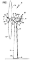
- FIG. 1 schematically shows a reference numeral 10 as a whole Wind turbine shown.
- This comprises a mast 11, which is a nacelle 12 carries, at about a common, horizontally oriented axis of rotation 13 freely rotatable a plurality of rotor blades 14, 15 are held.
- the machine nacelle 12 takes in conventional and therefore not shown in the drawing Detach a generator for conversion from that of the rotor blades 14, 15 provided mechanical kinetic energy into electrical energy, in the usual and therefore also not shown in the drawing For example, fed into a public power grid can be.
- a device (defrosting device 18) for at least partially de-icing of the rotor blades 14, 15 on, which is arranged in the nacelle 12 storage tank 20 for De-icing liquid comprises, which extends over a within the mast 11 extending Filling line 21 arranged with a foot 22 of the mast Filling connection 23 is in flow communication.
- the storage tank 20 is arranged via an output line 25 with a arranged in a rotor hub 27 Distributor unit 29 in flow communication, via the one in the storage tank 20 arranged deicing fluid 31 each have a rotor blade 14 and 15 associated spray nozzles 34, 35 can be supplied. By means of Spray nozzles 34 and 35, the deicing liquid 31 on the rotor hub 27 adjacent arranged region of the rotor blades 14 and 15 sprayed become.
- the storage tank 20 preferably has a volume of about 100 Liters to about 300 liters.
- a feed pump 37 is connected in the output line 25, which is associated with an electrical control unit 39, over in the Drawing not shown electrical connection lines with an operating data acquisition unit 41 as well as the ambient temperature of the Wind turbine 10 and the humidity of the ambient air of the wind turbine 10 detecting electrical measuring unit 43 is coupled.
- the measuring unit 43 provides the control unit 39 of the air temperature and the Humidity corresponding measurement signal ready as an input signal, and the Control unit 39 controls in dependence on the provided by the measuring unit 43 Measurement data, the feed pump 37 as needed, so that by distribution of deicing liquid 31 on the rotor blades 14 and 15, ice formation can be avoided.
- the storage tank 20 is associated with a level sensor 45, which is a level the storage tank 20 provides corresponding level signal.
- a level sensor 45 as well as the control unit 39 is known per se and therefore not shown in the drawing electrical lines with the Operational data acquisition unit 41, which comprises a transmitter for wireless transmission of the operating and measured data of the deicing device 18 to a central monitoring device, not shown in the drawing, so that by means of the operation data acquisition unit 41 of the operating state the deicing device 18 as well as the temperature and humidity the ambient air of the wind turbine 10 wirelessly transmissible and thereby are centrally detectable.
- the deicing fluid becomes 31 sprayed in the rotor hub 27 on the rotor blades 14 and 15. Under the action of the centrifugal force then distributes the deicing fluid 31 evenly over the rotor blades 14 and 15, so that a Ice formation on the rotor blades 14, 15 can be reliably prevented and the rotor blades 14, 15 optionally in a cost effective manner of ice can be exempted.
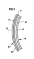
- FIGS. 2, 3 and 4 show the already explained wind power plant 10, wherein at least partially de-icing of the rotor blades 14, 15 and 16, a deicing device 48 is used which is largely is configured identically as the above with reference to Figure 1 explained deicing device 18.
- a deicing device 48 is used which is largely is configured identically as the above with reference to Figure 1 explained deicing device 18.
- FIGS. 2, 3 and 4 Components used the same reference as in Figure 1. To avoid of repetitions in this regard is fully in content to the preceding Explanatory reference.
- the deicing device 48 is different from the deicing device 18 only in that they additionally perforated covers 51, 52, 53, which are each designed as perforated steel sheet 55 and a Variety of through holes 56 with a diameter of maximum about 0.1 mm.
- the bore diameter is about 80 ⁇ m.
- a diameter of less than about 0.1 mm has the advantage that effective defrosting using a small amount of fluid is achievable. So can within about an hour about 1 liter of deicing fluid applied to the outside of the covers 51, 52, 53 become.
- the covers 51, 52 and 53 each cover a related on the direction of rotation 58 front edge region of the rotor blades 14, 15 and 16, wherein the covers 51, 52, 53 each at a small distance to the respective rotor blades 14, 15 and 16 are arranged so that between the covers 51, 52, 53 and the respective rotor blade 15, 16, respectively Interspace 60 is formed.
- the rotor blades 14, 15, 16 are each designed as a dimensionally stable hollow body, the is formed of a glass fiber reinforced plastic wall 62 whose outer side a coating 63, for example a lacquer layer, carries. Under Formation of the intermediate space 60 are the perforated covers 51, 52, 53 in an approximately the material thickness of the covers 51, 52, 53 corresponding Distance to the coating 63 on the respective rotor blades 14, 15 or 16 held.
- the deicing device 48 shown in Figures 2, 3 and 4 can the deicing fluid 31 by means of the respective rotor blade 14, 15, 16 associated spray nozzle in the rotor hub 27 adjacent area in the gap 60 are sprayed. Within the space 60 Then the deicing liquid 31 under the action of centrifugal force evenly distributed, and through the through holes 56 of the perforated Covers 51, 52, 53 can then pass the deicing fluid 31 of the outside of the covers 51, 52, 53 are supplied to Avoiding ice formation or deicing of the surface.
- FIG 5 the already explained wind turbine 10 is shown, wherein the area deicing of the rotor blades 14, 15 a deicing device 68 is used.
- the latter differs from the one above with reference to Figures 2, 3 and 4 explained defrosting device 48 only in that for introducing the deicing liquid 31st in the space 60 between the respective rotor blade 14, 15 and 16th and the associated cover 51, 52 and 53, respectively, starting from the distributor unit 29 within the respective rotor blade 14, 15 each have a distribution line 70, 71 extends, over which the gap 60 with the distribution unit 29 is in fluid communication.
- This has the advantage that by means of Feed pump 37, the deicing fluid 31 under pressure directly in the gap 60 can be pressed. This can be a special uniform and within a short time distribution of the deicing fluid 30 within the space 60, starting from the rotor hub 27 adjacent arranged area can be achieved up to the rotor tip.
Landscapes
- Engineering & Computer Science (AREA)
- Life Sciences & Earth Sciences (AREA)
- Sustainable Development (AREA)
- Sustainable Energy (AREA)
- Chemical & Material Sciences (AREA)
- Combustion & Propulsion (AREA)
- Mechanical Engineering (AREA)
- General Engineering & Computer Science (AREA)
- Wind Motors (AREA)
Priority Applications (1)
| Application Number | Priority Date | Filing Date | Title |
|---|---|---|---|
| EP03015864A EP1496251A1 (fr) | 2003-07-11 | 2003-07-11 | Dispositif de dégivrage des aubes d'une éolienne et éolienne avec ledit dispositif |
Applications Claiming Priority (1)
| Application Number | Priority Date | Filing Date | Title |
|---|---|---|---|
| EP03015864A EP1496251A1 (fr) | 2003-07-11 | 2003-07-11 | Dispositif de dégivrage des aubes d'une éolienne et éolienne avec ledit dispositif |
Publications (1)
| Publication Number | Publication Date |
|---|---|
| EP1496251A1 true EP1496251A1 (fr) | 2005-01-12 |
Family
ID=33442789
Family Applications (1)
| Application Number | Title | Priority Date | Filing Date |
|---|---|---|---|
| EP03015864A Withdrawn EP1496251A1 (fr) | 2003-07-11 | 2003-07-11 | Dispositif de dégivrage des aubes d'une éolienne et éolienne avec ledit dispositif |
Country Status (1)
| Country | Link |
|---|---|
| EP (1) | EP1496251A1 (fr) |
Cited By (14)
| Publication number | Priority date | Publication date | Assignee | Title |
|---|---|---|---|---|
| WO2006066591A1 (fr) * | 2004-12-21 | 2006-06-29 | Lm Glasfiber A/S | Aerogenerateur marin dote d'un dispositif de prevention de la formation de glace |
| GB2452488A (en) * | 2007-09-04 | 2009-03-11 | Ulrik Rasmussen | Controlling an aerodynamic structure by dispensing a fluid |
| WO2009080043A3 (fr) * | 2007-12-21 | 2010-03-25 | Vestas Wind Systems A/S | Aérogénérateur à échangeur de chaleur |
| CN101548101B (zh) * | 2007-05-18 | 2011-11-09 | 三菱重工业株式会社 | 风力发电装置 |
| EP2320074A3 (fr) * | 2009-11-05 | 2014-04-02 | General Electric Company | Systèmes et procédé de fonctionnement d'une éolienne disposant d'un contrôle de flux actif |
| CN103807110A (zh) * | 2014-01-22 | 2014-05-21 | 刘中威 | 一种风力发电机转子叶片电热融冰温度监测系统 |
| CN103821674A (zh) * | 2014-01-22 | 2014-05-28 | 刘中威 | 一种风力发电机转子叶片电热融冰系统及制造方法 |
| CN107676233A (zh) * | 2017-11-09 | 2018-02-09 | 华润电力投资有限公司深圳分公司 | 一种风力发电机组及其叶片除冰系统 |
| CN112901430A (zh) * | 2021-04-06 | 2021-06-04 | 兰州理工大学 | 一种助爬式可变形风电叶片除冰专用设备 |
| CN113357104A (zh) * | 2021-07-23 | 2021-09-07 | 北京质为科技有限公司 | 多用途自动除冰机器人系统与有除冰需要的设备 |
| CN114718823A (zh) * | 2022-05-13 | 2022-07-08 | 国家电投集团广西兴安风电有限公司 | 一种用于风电机组覆冰监测用除冰装置 |
| CN116658382A (zh) * | 2023-07-28 | 2023-08-29 | 傲拓科技股份有限公司 | 一种基于plc环境数据分析的风力发电扇叶除冰控制系统 |
| WO2024108238A1 (fr) | 2022-11-22 | 2024-05-30 | Pegasus Research & Development Gmbh | Dispositif de protection contre le givre |
| WO2024108244A1 (fr) | 2022-11-22 | 2024-05-30 | Pegasus Research & Development Gmbh | Dispositif de protection contre le givre |
Citations (5)
| Publication number | Priority date | Publication date | Assignee | Title |
|---|---|---|---|---|
| US2412846A (en) * | 1943-06-02 | 1946-12-17 | Bendix Aviat Corp | Means for supplying inflammable antifreeze fluids for use on airfoil surfaces so as t prevent explosion of the fluid |
| FR1182081A (fr) * | 1956-09-13 | 1959-06-22 | Plessey Co Ltd | Dispositif dégivreur pour turbines à entraînement par le vent relatif |
| GB2112339A (en) * | 1981-11-13 | 1983-07-20 | T K S | Porous panel |
| GB2130158A (en) * | 1982-11-15 | 1984-05-31 | Fiber Materials | Deicing aircraft surfaces |
| DE19528862A1 (de) * | 1995-08-05 | 1997-02-06 | Aloys Wobben | Verfahren zum Enteisen eines Rotorblattes einer Windenergieanlage sowie zur Durchführung des Verfahrens geeignetes Rotorblatt |
-
2003
- 2003-07-11 EP EP03015864A patent/EP1496251A1/fr not_active Withdrawn
Patent Citations (5)
| Publication number | Priority date | Publication date | Assignee | Title |
|---|---|---|---|---|
| US2412846A (en) * | 1943-06-02 | 1946-12-17 | Bendix Aviat Corp | Means for supplying inflammable antifreeze fluids for use on airfoil surfaces so as t prevent explosion of the fluid |
| FR1182081A (fr) * | 1956-09-13 | 1959-06-22 | Plessey Co Ltd | Dispositif dégivreur pour turbines à entraînement par le vent relatif |
| GB2112339A (en) * | 1981-11-13 | 1983-07-20 | T K S | Porous panel |
| GB2130158A (en) * | 1982-11-15 | 1984-05-31 | Fiber Materials | Deicing aircraft surfaces |
| DE19528862A1 (de) * | 1995-08-05 | 1997-02-06 | Aloys Wobben | Verfahren zum Enteisen eines Rotorblattes einer Windenergieanlage sowie zur Durchführung des Verfahrens geeignetes Rotorblatt |
Cited By (20)
| Publication number | Priority date | Publication date | Assignee | Title |
|---|---|---|---|---|
| WO2006066591A1 (fr) * | 2004-12-21 | 2006-06-29 | Lm Glasfiber A/S | Aerogenerateur marin dote d'un dispositif de prevention de la formation de glace |
| CN101548101B (zh) * | 2007-05-18 | 2011-11-09 | 三菱重工业株式会社 | 风力发电装置 |
| GB2452488A (en) * | 2007-09-04 | 2009-03-11 | Ulrik Rasmussen | Controlling an aerodynamic structure by dispensing a fluid |
| GB2452488B (en) * | 2007-09-04 | 2012-10-10 | Ulrik Rasmussen | Controlling an aerodynamic structure by dispensing a fluid |
| WO2009080043A3 (fr) * | 2007-12-21 | 2010-03-25 | Vestas Wind Systems A/S | Aérogénérateur à échangeur de chaleur |
| CN101925742B (zh) * | 2007-12-21 | 2012-11-14 | 维斯塔斯风力系统集团公司 | 具有热交换器的风力涡轮发电机 |
| EP2320074A3 (fr) * | 2009-11-05 | 2014-04-02 | General Electric Company | Systèmes et procédé de fonctionnement d'une éolienne disposant d'un contrôle de flux actif |
| CN103821674B (zh) * | 2014-01-22 | 2017-04-26 | 刘中威 | 一种风力发电机转子叶片电热融冰系统及制造方法 |
| CN103821674A (zh) * | 2014-01-22 | 2014-05-28 | 刘中威 | 一种风力发电机转子叶片电热融冰系统及制造方法 |
| CN103807110B (zh) * | 2014-01-22 | 2017-03-15 | 刘中威 | 一种风力发电机转子叶片电热融冰温度监测系统 |
| CN103807110A (zh) * | 2014-01-22 | 2014-05-21 | 刘中威 | 一种风力发电机转子叶片电热融冰温度监测系统 |
| CN107676233A (zh) * | 2017-11-09 | 2018-02-09 | 华润电力投资有限公司深圳分公司 | 一种风力发电机组及其叶片除冰系统 |
| CN112901430A (zh) * | 2021-04-06 | 2021-06-04 | 兰州理工大学 | 一种助爬式可变形风电叶片除冰专用设备 |
| CN113357104A (zh) * | 2021-07-23 | 2021-09-07 | 北京质为科技有限公司 | 多用途自动除冰机器人系统与有除冰需要的设备 |
| CN113357104B (zh) * | 2021-07-23 | 2022-09-02 | 北京质为科技有限公司 | 多用途自动除冰机器人系统与有除冰需要的设备 |
| CN114718823A (zh) * | 2022-05-13 | 2022-07-08 | 国家电投集团广西兴安风电有限公司 | 一种用于风电机组覆冰监测用除冰装置 |
| WO2024108238A1 (fr) | 2022-11-22 | 2024-05-30 | Pegasus Research & Development Gmbh | Dispositif de protection contre le givre |
| WO2024108244A1 (fr) | 2022-11-22 | 2024-05-30 | Pegasus Research & Development Gmbh | Dispositif de protection contre le givre |
| CN116658382A (zh) * | 2023-07-28 | 2023-08-29 | 傲拓科技股份有限公司 | 一种基于plc环境数据分析的风力发电扇叶除冰控制系统 |
| CN116658382B (zh) * | 2023-07-28 | 2023-10-27 | 傲拓科技股份有限公司 | 一种基于环境数据分析的风力发电扇叶除冰控制系统 |
Similar Documents
| Publication | Publication Date | Title |
|---|---|---|
| EP1496251A1 (fr) | Dispositif de dégivrage des aubes d'une éolienne et éolienne avec ledit dispositif | |
| DE19731918B4 (de) | Windenergieanlage | |
| EP1844323B1 (fr) | Dispositif et procede de determination de l'humidite dans un milieu | |
| DE102007036870B4 (de) | Verstellbare Düsenwinkel | |
| DE102009046293B4 (de) | Rotorblatt mit Entwässerungsbohrung | |
| DE10022129C2 (de) | Verfahren zum Betreiben einer Windenergieanlage sowie Windenergieanlage zur Durchführung des Verfahrens | |
| WO2010091675A2 (fr) | Éolienne pourvue de capteurs de surveillance | |
| WO2014202164A1 (fr) | Pale de rotor (10) d'une éolienne, système de dégivrage et procédé | |
| DE102018104827B4 (de) | Unbemannter Drehflügler, System und Verfahren zum Ausbringen eines Spritzguts | |
| DE102005048805A1 (de) | Verfahren zum Betreiben einer Windenergieanlage | |
| DE102021102659B3 (de) | Verfahren zur Erkennung einer Ausbildung von Eis an einem rotierenden Rotorblatt und Rotorblatteinrichtung | |
| DE10320347B4 (de) | Sprühanlage | |
| EP2078937B1 (fr) | Dispositif de détermination d'un volume d'un récipient de stockage | |
| WO2013174573A1 (fr) | Système de baguette d'étanchéité | |
| DE10233102B4 (de) | Rotorblatt für Windkraftanlagen | |
| DE20021026U1 (de) | Fettschmieranlage, Fettbehälter und Windkraftanlage | |
| DE102011054610A1 (de) | Verfahren und Vorrichtung zum Aufbringen von Frostschutzmittel auf einen Fahrdraht sowie mit einer solchen Vorrichtung ausgestattetes, elektrisch betriebenes Fahrzeug | |
| EP3983674B1 (fr) | Procédé permettant de détecter la vitesse du vent, procédé permettant de commander une éolienne, procédé permettant de commander un parc éolien; et éolienne | |
| EP0962594A2 (fr) | Dispositif de pulvérisation de sel à dégeler immobile pour la distribution de liquide de sel à dégeler | |
| DE102005026644B4 (de) | Verfahren zur Retention von Niederschlagswasser in einer Versickerungsfläche im Gebiet der Entstehung | |
| DE202004008632U1 (de) | Fahrdrahtenteisungsanlage | |
| AT516021B1 (de) | Vorrichtung und Verfahren zur Messung eines Druckes | |
| EP3615792B1 (fr) | Pale de rotor d'éolienne et procédé de fabrication d'une pale de rotor d'éolienne | |
| DE3202467C2 (de) | Anordnung zum Brandschutz von Gebäuden | |
| WO2022122257A1 (fr) | Procédé et dispositif de mise en fonctionnement d'une éolienne |
Legal Events
| Date | Code | Title | Description |
|---|---|---|---|
| PUAI | Public reference made under article 153(3) epc to a published international application that has entered the european phase |
Free format text: ORIGINAL CODE: 0009012 |
|
| AK | Designated contracting states |
Kind code of ref document: A1 Designated state(s): AT BE BG CH CY CZ DE DK EE ES FI FR GB GR HU IE IT LI LU MC NL PT RO SE SI SK TR |
|
| AX | Request for extension of the european patent |
Extension state: AL LT LV MK |
|
| AKX | Designation fees paid | ||
| REG | Reference to a national code |
Ref country code: DE Ref legal event code: 8566 |
|
| STAA | Information on the status of an ep patent application or granted ep patent |
Free format text: STATUS: THE APPLICATION IS DEEMED TO BE WITHDRAWN |
|
| 18D | Application deemed to be withdrawn |
Effective date: 20050713 |