EP1496291A2 - Variateur continu à poulies coniques avec capteur de couple - Google Patents
Variateur continu à poulies coniques avec capteur de couple Download PDFInfo
- Publication number
- EP1496291A2 EP1496291A2 EP04016037A EP04016037A EP1496291A2 EP 1496291 A2 EP1496291 A2 EP 1496291A2 EP 04016037 A EP04016037 A EP 04016037A EP 04016037 A EP04016037 A EP 04016037A EP 1496291 A2 EP1496291 A2 EP 1496291A2
- Authority
- EP
- European Patent Office
- Prior art keywords
- cylinder
- axially
- sensor
- torque sensor
- bevel gear
- Prior art date
- Legal status (The legal status is an assumption and is not a legal conclusion. Google has not performed a legal analysis and makes no representation as to the accuracy of the status listed.)
- Granted
Links
- 230000005540 biological transmission Effects 0.000 title description 8
- 238000005096 rolling process Methods 0.000 claims description 21
- 230000001419 dependent effect Effects 0.000 claims description 2
- 238000004519 manufacturing process Methods 0.000 description 3
- 230000035939 shock Effects 0.000 description 2
- 206010024264 Lethargy Diseases 0.000 description 1
- 230000002411 adverse Effects 0.000 description 1
- 238000006243 chemical reaction Methods 0.000 description 1
- 238000010276 construction Methods 0.000 description 1
- 238000001816 cooling Methods 0.000 description 1
- 230000000254 damaging effect Effects 0.000 description 1
- 230000006866 deterioration Effects 0.000 description 1
- 230000001627 detrimental effect Effects 0.000 description 1
- 238000010586 diagram Methods 0.000 description 1
- 238000006073 displacement reaction Methods 0.000 description 1
- 230000000694 effects Effects 0.000 description 1
- 238000005461 lubrication Methods 0.000 description 1
- 230000002093 peripheral effect Effects 0.000 description 1
Images
Classifications
-
- F—MECHANICAL ENGINEERING; LIGHTING; HEATING; WEAPONS; BLASTING
- F16—ENGINEERING ELEMENTS AND UNITS; GENERAL MEASURES FOR PRODUCING AND MAINTAINING EFFECTIVE FUNCTIONING OF MACHINES OR INSTALLATIONS; THERMAL INSULATION IN GENERAL
- F16H—GEARING
- F16H55/00—Elements with teeth or friction surfaces for conveying motion; Worms, pulleys or sheaves for gearing mechanisms
- F16H55/32—Friction members
- F16H55/52—Pulleys or friction discs of adjustable construction
- F16H55/56—Pulleys or friction discs of adjustable construction of which the bearing parts are relatively axially adjustable
-
- F—MECHANICAL ENGINEERING; LIGHTING; HEATING; WEAPONS; BLASTING
- F16—ENGINEERING ELEMENTS AND UNITS; GENERAL MEASURES FOR PRODUCING AND MAINTAINING EFFECTIVE FUNCTIONING OF MACHINES OR INSTALLATIONS; THERMAL INSULATION IN GENERAL
- F16H—GEARING
- F16H61/00—Control functions within control units of change-speed- or reversing-gearings for conveying rotary motion ; Control of exclusively fluid gearing, friction gearing, gearings with endless flexible members or other particular types of gearing
- F16H61/66—Control functions within control units of change-speed- or reversing-gearings for conveying rotary motion ; Control of exclusively fluid gearing, friction gearing, gearings with endless flexible members or other particular types of gearing specially adapted for continuously variable gearings
- F16H61/662—Control functions within control units of change-speed- or reversing-gearings for conveying rotary motion ; Control of exclusively fluid gearing, friction gearing, gearings with endless flexible members or other particular types of gearing specially adapted for continuously variable gearings with endless flexible members
- F16H61/66272—Control functions within control units of change-speed- or reversing-gearings for conveying rotary motion ; Control of exclusively fluid gearing, friction gearing, gearings with endless flexible members or other particular types of gearing specially adapted for continuously variable gearings with endless flexible members characterised by means for controlling the torque transmitting capability of the gearing
Definitions
- the invention relates to a continuously variable bevel gear with each two on the input and output shaft arranged conical disks and a between these circulating transmission means, wherein on each wave one Cone pulley axially displaceable by a pressure cylinder rotating with the shaft is, while the other two conical disks axially supported are.
- At least one of the axially fixedly supported conical disks for Load-dependent generation of contact forces a sensor for the transmitted Assigned torque.
- This will be pressure medium with on its own or the other wave in the local pressure cylinder pressure prevailing there.
- the sensor also has at least one rolling element, the is arranged between two opposing Anpresskurven, of which is associated with one of the axially fixedly supported cone pulley.
- the other Anpresskurve is an axially adjustable part of a person sitting on the shaft Cylinder-piston units assigned.
- Such a continuously variable cone pulley transmission is, for example known from DE-A-28 46 580.
- the torque is frictionally engaged by the drive disc set transferred to the driven pulley, the contact pressure the discs on the case between the sets of discs Transmission means in the form of a chain by oil pressure in the pressure cylinders is built. It is known for a good efficiency of such frictional transmission and for the lowest possible wear of Chain and discs the contact forces of the discs depending on the transmitted To regulate torque, including the addressed torque sensor serves, which is preferably located directly in the power flow of the drive disc set.
- the torque is thereby from an axially adjustable part of the cylinder-piston unit of the torque sensor transmitted to rolling elements, which usually be formed by several balls. These balls guide that Torque then on a sensor plate on, which is known in the axial firmly supported cone pulley is to be integrated.
- the rolling elements sit in it Ball pockets provided on the axially adjustable part and on the sensor plate are formed and in the circumferential direction as inclined surfaces, have opposite Anpresskurven. This builds up a proportional to the torque axial force, which is the adjustable part of Cylinder-piston units of the torque sensor against the oil inside of the cylinder-piston unit presses.
- the axial adjustment the adjustable part of the cylinder-piston unit a drain gap adjusted for the oil flowing through the cylinder-piston unit.
- the oil is throttled so much that a balance between the hydraulic force from the oil pressure of the cylinder-piston unit and the adjusted by the rolling elements generated axial force. This allows the pressure within of the system within a varying torque within only a few Milliseconds, and thus in particular faster than e.g. a control loop from torque measuring shaft, regulator and proportional solenoid valve.
- torque sensor also acts as a very fast Acting memory: It must be taken into account that when suddenly occurring torque peak quickly increase the pressures in the pulley sets need to avoid a harmful chain chute.
- the torque sensor as described above is able to store Oil to compensate for oil compressibility and system elasticity directly in the disc sets assigned to promote printing cylinder, thereby he short term, a pump with a high flow of, for example can replace more than 30 l / min.
- the torque sensor acts as torsional vibration damper.
- This object is achieved in that the one or the intended Rolling rolling elements on an effective radius, which is at least as large as the outer radius of the piston of the cylinder-piston unit.
- the invention is based on the finding that in the hitherto for Used constructions the inherent elasticity of individual components as well as relatively high inert masses of high dynamics in the readjustment are detrimental to torque changes. This is through the now proposed minimized constructive embodiment.
- the Anpresskurven for the rolling elements on the axially fixedly supported conical disk to arrange on a circumferential ring on this.
- This can be achieved that the fixed cone pulley gets stiffer. This reduces the intrinsic elasticity of this component. Besides that is so also to achieve that even with a lesser number of over the Scope distributed rolling elements this does not lead to an undesirable, harmful Tread waviness of the fixed conical disk leads.
- a small number of rolling elements reduces the one hand, the inertial mass, what the dynamics the readjustment benefits. On the other hand, there are fewer in the production of expensive Anpresskurven necessary.
- the provided on the axially fixed conical disk is provided encircling ring formed integrally with this conical disk. hereby In particular, an even more cost-effective production can be achieved.
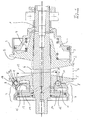
- Figure 1 shows the schematic diagram of a pulley set for a bevel gear. Below the center line, the prior art is shown. Above the center line is a further development of the invention
- the disc set sits on a shaft 1, on which to set and maintain the desired gear ratio an axially displaceable cone pulley 2 is arranged, which is connected to a peripheral connected to it Apron 3 forms the cylinder of a cylinder-piston unit 4.
- the axially adjustable conical disk 2 opposite is a firmly supported Conical disk 5. There is no running between the respective pairs of conical disks shown in detail chain 6 as a circulating transmission medium.
- the cylinder-piston unit 4 is by a pressure medium source, not shown Supplied pressure medium.
- a torque sensor 7 the pressure in Cylinder-piston unit 4 determined. From the torque sensor effluent Pressure oil can be depressurized on the transmission means 6 to its lubrication and Cooling be delivered.
- the torque sensor sits directly in the power flow, preferably the Drive disk set.
- the transmitted torque is from the movable Cylinder 8 of designed as a cylinder-piston unit torque sensor 7 transmitted to a plurality of rolling elements 9, between the cylinder 8 and the conical disk 5 are arranged. In the example shown here it is at the rolling elements to balls. Basically, but also roll or barrel-shaped rolling elements conceivable.
- the rolling elements 9 run in pockets 10, 11, in the conical disk 5 and in the cylinder 8 of the torque sensor 7 are incorporated. They have this Pockets in the circumferential direction inclined surfaces. This builds up a proportional to the torque axial force on the cylinder 8 against the oil in the chamber 12 of the torque sensor 7 presses. At a sudden occurring torque shock is caused by displacement of the cylinder 8 and so that the cylinder bottom 15 of the oil drain from the chamber 12 is closed and at the same time the oil in the chamber 12 to a corresponding Pressure increase at high speed in the cylinder-piston unit. 4 pumped the axially adjustable conical disk to there the corresponding To cause pressure increase, which avoids harmful slippage of the chain.
- the pockets 10 are with their Anpresskurven 16 in the embodiment according to the invention in a on the conical disk. 5 arranged ring 17 is provided.
- This ring has a stiffening effect on this cone pulley 5, so that it can be made thinner.
- This ring gives the possibility of having less rolling elements distributed around the circumference provide, without such a smaller number of rolling elements and Bags in which they run, a tread waviness at the conical disk 5 would result.
- the invention thus offers the overall possibility of the functionality of a continuously variable transmission and at the same time a more cost-effective production to reach.
Landscapes
- Engineering & Computer Science (AREA)
- General Engineering & Computer Science (AREA)
- Mechanical Engineering (AREA)
- Transmissions By Endless Flexible Members (AREA)
- Power Steering Mechanism (AREA)
- Retarders (AREA)
- Transmission Devices (AREA)
- Support Of The Bearing (AREA)
- Friction Gearing (AREA)
Applications Claiming Priority (2)
| Application Number | Priority Date | Filing Date | Title |
|---|---|---|---|
| DE10331470 | 2003-07-11 | ||
| DE10331470A DE10331470A1 (de) | 2003-07-11 | 2003-07-11 | Stufenlos einstellbares Kegelscheibengetriebe mit Drehmomentfühler |
Publications (3)
| Publication Number | Publication Date |
|---|---|
| EP1496291A2 true EP1496291A2 (fr) | 2005-01-12 |
| EP1496291A3 EP1496291A3 (fr) | 2005-10-19 |
| EP1496291B1 EP1496291B1 (fr) | 2007-01-31 |
Family
ID=33441733
Family Applications (1)
| Application Number | Title | Priority Date | Filing Date |
|---|---|---|---|
| EP04016037A Expired - Lifetime EP1496291B1 (fr) | 2003-07-11 | 2004-07-08 | Variateur continu à poulies coniques avec capteur de couple |
Country Status (5)
| Country | Link |
|---|---|
| US (1) | US20050014581A1 (fr) |
| EP (1) | EP1496291B1 (fr) |
| AT (1) | ATE353124T1 (fr) |
| CA (1) | CA2473445A1 (fr) |
| DE (2) | DE10331470A1 (fr) |
Families Citing this family (1)
| Publication number | Priority date | Publication date | Assignee | Title |
|---|---|---|---|---|
| JP4545131B2 (ja) * | 2006-09-29 | 2010-09-15 | 本田技研工業株式会社 | 動力伝達装置 |
Citations (1)
| Publication number | Priority date | Publication date | Assignee | Title |
|---|---|---|---|---|
| DE2846580A1 (de) | 1978-10-26 | 1980-04-30 | Piv Antrieb Reimers Kg Werner | Stufenlos einstellbares kegelscheibengetriebe |
Family Cites Families (9)
| Publication number | Priority date | Publication date | Assignee | Title |
|---|---|---|---|---|
| DE3028490C2 (de) * | 1980-07-26 | 1983-01-13 | P.I.V. Antrieb Werner Reimers GmbH & Co KG, 6380 Bad Homburg | Stufenlos einstellbares Kegelscheibengetriebe |
| DE4036398A1 (de) * | 1989-11-17 | 1991-05-23 | Piv Antrieb Reimers Kg Werner | Stufenlos einstellbares kegelscheibengetriebe |
| JP3961039B2 (ja) * | 1994-12-06 | 2007-08-15 | ルーク ゲトリーベ−ジステーメ ゲゼルシャフト ミット ベシュレンクテル ハフツング | トルクセンサ及び円錐形プーリー巻掛け式伝動装置 |
| DE19544644B4 (de) * | 1994-12-06 | 2008-03-27 | Luk Gs Verwaltungs Kg | Drehmomentfühler sowie damit ausgestattetes Kegelscheibenumschlingungsgetriebe |
| JP3532855B2 (ja) * | 1998-01-28 | 2004-05-31 | バートランド・フォーレ・コンポーネンツ・リミテッド | 多機能車両シート用回転リクライナー制御機構 |
| DE19909347B4 (de) * | 1998-03-10 | 2012-03-29 | Schaeffler Technologies Gmbh & Co. Kg | Getriebe |
| DE19921750B4 (de) * | 1998-05-18 | 2012-03-08 | Schaeffler Technologies Gmbh & Co. Kg | Getriebe |
| DE19939435A1 (de) * | 1998-08-28 | 2000-03-02 | Luk Getriebe Systeme Gmbh | Getriebe |
| DE19951950B4 (de) * | 1998-11-03 | 2013-02-28 | Schaeffler Technologies AG & Co. KG | Getriebe |
-
2003
- 2003-07-11 DE DE10331470A patent/DE10331470A1/de not_active Withdrawn
-
2004
- 2004-07-08 AT AT04016037T patent/ATE353124T1/de not_active IP Right Cessation
- 2004-07-08 EP EP04016037A patent/EP1496291B1/fr not_active Expired - Lifetime
- 2004-07-08 DE DE502004002821T patent/DE502004002821D1/de not_active Expired - Lifetime
- 2004-07-12 US US10/889,460 patent/US20050014581A1/en not_active Abandoned
- 2004-07-12 CA CA002473445A patent/CA2473445A1/fr not_active Abandoned
Patent Citations (1)
| Publication number | Priority date | Publication date | Assignee | Title |
|---|---|---|---|---|
| DE2846580A1 (de) | 1978-10-26 | 1980-04-30 | Piv Antrieb Reimers Kg Werner | Stufenlos einstellbares kegelscheibengetriebe |
Also Published As
| Publication number | Publication date |
|---|---|
| CA2473445A1 (fr) | 2005-01-11 |
| DE502004002821D1 (de) | 2007-03-22 |
| DE10331470A1 (de) | 2005-02-24 |
| EP1496291B1 (fr) | 2007-01-31 |
| US20050014581A1 (en) | 2005-01-20 |
| ATE353124T1 (de) | 2007-02-15 |
| EP1496291A3 (fr) | 2005-10-19 |
Similar Documents
| Publication | Publication Date | Title |
|---|---|---|
| DE2744947C3 (de) | Stufenlos einstellbares Kegelscheiben-Umschlingungsgetriebe | |
| DE4234294B4 (de) | Kegelscheibenumschlingungsgetriebe | |
| DE69702132T2 (de) | Steuersystem für ein stufenloses getriebe | |
| DE69907321T2 (de) | Stufenloses Toroidgetriebe | |
| DE2846580C2 (de) | Stufenlos einstellbares Kegelscheibengetriebe | |
| DE4036683B4 (de) | Stufenlos einstellbares Kegelscheibenumschlingungsgetriebe | |
| DE1278184B (de) | Reibkugelgetriebe | |
| CH623902A5 (fr) | ||
| DE2825730C2 (de) | Stufenlos einstellbares Reibrollengetriebe | |
| DE1081733B (de) | Steuereinrichtung an stufenlos verstellbaren Getrieben mit zwischen axial verschiebbaren Kegelscheibenpaaren laufenden Zugmittelstraengen und hydraulischer Verstelleinrichtung | |
| DE2318818A1 (de) | Regelgetriebe | |
| CH654386A5 (de) | Stufenlos einstellbares kegelscheibengetriebe. | |
| DE102010015724A1 (de) | Getriebe, insbesondere Verdichtergetriebe und Verfahren zur Verbesserung des Anfahrverhaltens eines solchen | |
| DE1455865A1 (de) | Vorrichtung zur Veraenderung der Verstellgeschwindigkeit zur Verwendung in Fahrzeugen bestimmter,hydraulisch gesteuerter,stufenlos verstellbarer Getriebe | |
| EP0985855B1 (fr) | Transmission à variation continue du type à poulies coniques et courroie, notamment pour véhicules automoteurs | |
| EP1496291B1 (fr) | Variateur continu à poulies coniques avec capteur de couple | |
| DE19964345B4 (de) | Stufenlos verstellbares Toroidgetriebe | |
| DE69018017T2 (de) | Stufenloses hydrostatisches Radialkolbengetriebe. | |
| DE112009003206T5 (de) | Stufenlos variables Reibgetriebe | |
| DE1264196B (de) | Kegelscheiben-Umschlingungsgetriebe | |
| DE19850135C2 (de) | Stufenlos verstellbares Toroidgetriebesystem | |
| DE843782C (de) | Mehrstufiges UEbersetzungsgetriebe mit Reibradwirkung, insbesondere fuer schnellaufende Maschinen | |
| DE2510852A1 (de) | Vorrichtung zum aufschlagen von fasermaterial | |
| DE2630035B2 (de) | Vorrichtung zum selbsttätigen Anstellen von paarweise gegeneinander angestellten Schrägwälzlagern einer Lagerung | |
| DE2857335A1 (de) | Kegelscheibengetriebe mit korrektureinrichtung in der festscheibe |
Legal Events
| Date | Code | Title | Description |
|---|---|---|---|
| PUAI | Public reference made under article 153(3) epc to a published international application that has entered the european phase |
Free format text: ORIGINAL CODE: 0009012 |
|
| AK | Designated contracting states |
Kind code of ref document: A2 Designated state(s): AT BE BG CH CY CZ DE DK EE ES FI FR GB GR HU IE IT LI LU MC NL PL PT RO SE SI SK TR |
|
| AX | Request for extension of the european patent |
Extension state: AL HR LT LV MK |
|
| PUAL | Search report despatched |
Free format text: ORIGINAL CODE: 0009013 |
|
| AK | Designated contracting states |
Kind code of ref document: A3 Designated state(s): AT BE BG CH CY CZ DE DK EE ES FI FR GB GR HU IE IT LI LU MC NL PL PT RO SE SI SK TR |
|
| AX | Request for extension of the european patent |
Extension state: AL HR LT LV MK |
|
| 17P | Request for examination filed |
Effective date: 20051207 |
|
| AKX | Designation fees paid |
Designated state(s): AT BE BG CH CY CZ DE DK EE ES FI FR GB GR HU IE IT LI LU MC NL PL PT RO SE SI SK TR |
|
| GRAP | Despatch of communication of intention to grant a patent |
Free format text: ORIGINAL CODE: EPIDOSNIGR1 |
|
| RTI1 | Title (correction) |
Free format text: CONTINUOUSLY VARIABLE CONE PULLEY TRANSMISSION WITH TORQUE SENSOR |
|
| GRAS | Grant fee paid |
Free format text: ORIGINAL CODE: EPIDOSNIGR3 |
|
| GRAA | (expected) grant |
Free format text: ORIGINAL CODE: 0009210 |
|
| AK | Designated contracting states |
Kind code of ref document: B1 Designated state(s): AT BE BG CH CY CZ DE DK EE ES FI FR GB GR HU IE IT LI LU MC NL PL PT RO SE SI SK TR |
|
| PG25 | Lapsed in a contracting state [announced via postgrant information from national office to epo] |
Ref country code: PL Free format text: LAPSE BECAUSE OF FAILURE TO SUBMIT A TRANSLATION OF THE DESCRIPTION OR TO PAY THE FEE WITHIN THE PRESCRIBED TIME-LIMIT Effective date: 20070131 Ref country code: NL Free format text: LAPSE BECAUSE OF FAILURE TO SUBMIT A TRANSLATION OF THE DESCRIPTION OR TO PAY THE FEE WITHIN THE PRESCRIBED TIME-LIMIT Effective date: 20070131 Ref country code: IE Free format text: LAPSE BECAUSE OF FAILURE TO SUBMIT A TRANSLATION OF THE DESCRIPTION OR TO PAY THE FEE WITHIN THE PRESCRIBED TIME-LIMIT Effective date: 20070131 Ref country code: SI Free format text: LAPSE BECAUSE OF FAILURE TO SUBMIT A TRANSLATION OF THE DESCRIPTION OR TO PAY THE FEE WITHIN THE PRESCRIBED TIME-LIMIT Effective date: 20070131 Ref country code: DK Free format text: LAPSE BECAUSE OF FAILURE TO SUBMIT A TRANSLATION OF THE DESCRIPTION OR TO PAY THE FEE WITHIN THE PRESCRIBED TIME-LIMIT Effective date: 20070131 |
|
| REG | Reference to a national code |
Ref country code: GB Ref legal event code: FG4D Free format text: NOT ENGLISH |
|
| REG | Reference to a national code |
Ref country code: CH Ref legal event code: EP |
|
| REG | Reference to a national code |
Ref country code: IE Ref legal event code: FG4D Free format text: LANGUAGE OF EP DOCUMENT: GERMAN |
|
| REF | Corresponds to: |
Ref document number: 502004002821 Country of ref document: DE Date of ref document: 20070322 Kind code of ref document: P |
|
| PG25 | Lapsed in a contracting state [announced via postgrant information from national office to epo] |
Ref country code: SE Free format text: LAPSE BECAUSE OF FAILURE TO SUBMIT A TRANSLATION OF THE DESCRIPTION OR TO PAY THE FEE WITHIN THE PRESCRIBED TIME-LIMIT Effective date: 20070430 |
|
| PG25 | Lapsed in a contracting state [announced via postgrant information from national office to epo] |
Ref country code: BG Free format text: LAPSE BECAUSE OF FAILURE TO SUBMIT A TRANSLATION OF THE DESCRIPTION OR TO PAY THE FEE WITHIN THE PRESCRIBED TIME-LIMIT Effective date: 20070501 |
|
| PG25 | Lapsed in a contracting state [announced via postgrant information from national office to epo] |
Ref country code: ES Free format text: LAPSE BECAUSE OF FAILURE TO SUBMIT A TRANSLATION OF THE DESCRIPTION OR TO PAY THE FEE WITHIN THE PRESCRIBED TIME-LIMIT Effective date: 20070512 |
|
| GBT | Gb: translation of ep patent filed (gb section 77(6)(a)/1977) |
Effective date: 20070502 |
|
| PG25 | Lapsed in a contracting state [announced via postgrant information from national office to epo] |
Ref country code: PT Free format text: LAPSE BECAUSE OF FAILURE TO SUBMIT A TRANSLATION OF THE DESCRIPTION OR TO PAY THE FEE WITHIN THE PRESCRIBED TIME-LIMIT Effective date: 20070702 |
|
| NLV1 | Nl: lapsed or annulled due to failure to fulfill the requirements of art. 29p and 29m of the patents act | ||
| ET | Fr: translation filed | ||
| REG | Reference to a national code |
Ref country code: IE Ref legal event code: FD4D |
|
| PG25 | Lapsed in a contracting state [announced via postgrant information from national office to epo] |
Ref country code: SK Free format text: LAPSE BECAUSE OF FAILURE TO SUBMIT A TRANSLATION OF THE DESCRIPTION OR TO PAY THE FEE WITHIN THE PRESCRIBED TIME-LIMIT Effective date: 20070131 |
|
| PLBE | No opposition filed within time limit |
Free format text: ORIGINAL CODE: 0009261 |
|
| STAA | Information on the status of an ep patent application or granted ep patent |
Free format text: STATUS: NO OPPOSITION FILED WITHIN TIME LIMIT |
|
| PG25 | Lapsed in a contracting state [announced via postgrant information from national office to epo] |
Ref country code: CZ Free format text: LAPSE BECAUSE OF FAILURE TO SUBMIT A TRANSLATION OF THE DESCRIPTION OR TO PAY THE FEE WITHIN THE PRESCRIBED TIME-LIMIT Effective date: 20070131 Ref country code: RO Free format text: LAPSE BECAUSE OF FAILURE TO SUBMIT A TRANSLATION OF THE DESCRIPTION OR TO PAY THE FEE WITHIN THE PRESCRIBED TIME-LIMIT Effective date: 20070131 |
|
| 26N | No opposition filed |
Effective date: 20071101 |
|
| BERE | Be: lapsed |
Owner name: PIV DRIVES G.M.B.H. Effective date: 20070731 |
|
| PG25 | Lapsed in a contracting state [announced via postgrant information from national office to epo] |
Ref country code: GR Free format text: LAPSE BECAUSE OF FAILURE TO SUBMIT A TRANSLATION OF THE DESCRIPTION OR TO PAY THE FEE WITHIN THE PRESCRIBED TIME-LIMIT Effective date: 20070501 Ref country code: MC Free format text: LAPSE BECAUSE OF NON-PAYMENT OF DUE FEES Effective date: 20070731 |
|
| PG25 | Lapsed in a contracting state [announced via postgrant information from national office to epo] |
Ref country code: BE Free format text: LAPSE BECAUSE OF NON-PAYMENT OF DUE FEES Effective date: 20070731 |
|
| PG25 | Lapsed in a contracting state [announced via postgrant information from national office to epo] |
Ref country code: AT Free format text: LAPSE BECAUSE OF NON-PAYMENT OF DUE FEES Effective date: 20070708 |
|
| PG25 | Lapsed in a contracting state [announced via postgrant information from national office to epo] |
Ref country code: EE Free format text: LAPSE BECAUSE OF FAILURE TO SUBMIT A TRANSLATION OF THE DESCRIPTION OR TO PAY THE FEE WITHIN THE PRESCRIBED TIME-LIMIT Effective date: 20070131 |
|
| REG | Reference to a national code |
Ref country code: CH Ref legal event code: PL |
|
| PG25 | Lapsed in a contracting state [announced via postgrant information from national office to epo] |
Ref country code: LI Free format text: LAPSE BECAUSE OF NON-PAYMENT OF DUE FEES Effective date: 20080731 Ref country code: CH Free format text: LAPSE BECAUSE OF NON-PAYMENT OF DUE FEES Effective date: 20080731 |
|
| PG25 | Lapsed in a contracting state [announced via postgrant information from national office to epo] |
Ref country code: CY Free format text: LAPSE BECAUSE OF FAILURE TO SUBMIT A TRANSLATION OF THE DESCRIPTION OR TO PAY THE FEE WITHIN THE PRESCRIBED TIME-LIMIT Effective date: 20070131 |
|
| PG25 | Lapsed in a contracting state [announced via postgrant information from national office to epo] |
Ref country code: LU Free format text: LAPSE BECAUSE OF NON-PAYMENT OF DUE FEES Effective date: 20070708 |
|
| PG25 | Lapsed in a contracting state [announced via postgrant information from national office to epo] |
Ref country code: HU Free format text: LAPSE BECAUSE OF FAILURE TO SUBMIT A TRANSLATION OF THE DESCRIPTION OR TO PAY THE FEE WITHIN THE PRESCRIBED TIME-LIMIT Effective date: 20070801 Ref country code: TR Free format text: LAPSE BECAUSE OF FAILURE TO SUBMIT A TRANSLATION OF THE DESCRIPTION OR TO PAY THE FEE WITHIN THE PRESCRIBED TIME-LIMIT Effective date: 20070131 |
|
| REG | Reference to a national code |
Ref country code: DE Ref legal event code: R082 Ref document number: 502004002821 Country of ref document: DE Representative=s name: JANY UND PETERSEN PATENTANWAELTE PARTNERSCHAFT, DE Ref country code: DE Ref legal event code: R082 Ref document number: 502004002821 Country of ref document: DE Representative=s name: PETERSEN, FRANK, DIPL.-ING., DE |
|
| REG | Reference to a national code |
Ref country code: DE Ref legal event code: R082 Ref document number: 502004002821 Country of ref document: DE Representative=s name: PETERSEN, FRANK, DIPL.-ING., DE |
|
| REG | Reference to a national code |
Ref country code: FR Ref legal event code: PLFP Year of fee payment: 13 |
|
| REG | Reference to a national code |
Ref country code: FR Ref legal event code: PLFP Year of fee payment: 14 |
|
| REG | Reference to a national code |
Ref country code: FR Ref legal event code: PLFP Year of fee payment: 15 |
|
| PGFP | Annual fee paid to national office [announced via postgrant information from national office to epo] |
Ref country code: FR Payment date: 20200623 Year of fee payment: 17 Ref country code: FI Payment date: 20200623 Year of fee payment: 17 |
|
| PGFP | Annual fee paid to national office [announced via postgrant information from national office to epo] |
Ref country code: GB Payment date: 20200624 Year of fee payment: 17 |
|
| PGFP | Annual fee paid to national office [announced via postgrant information from national office to epo] |
Ref country code: DE Payment date: 20200622 Year of fee payment: 17 |
|
| PGFP | Annual fee paid to national office [announced via postgrant information from national office to epo] |
Ref country code: IT Payment date: 20200622 Year of fee payment: 17 |
|
| REG | Reference to a national code |
Ref country code: DE Ref legal event code: R119 Ref document number: 502004002821 Country of ref document: DE |
|
| REG | Reference to a national code |
Ref country code: FI Ref legal event code: MAE |
|
| GBPC | Gb: european patent ceased through non-payment of renewal fee |
Effective date: 20210708 |
|
| PG25 | Lapsed in a contracting state [announced via postgrant information from national office to epo] |
Ref country code: GB Free format text: LAPSE BECAUSE OF NON-PAYMENT OF DUE FEES Effective date: 20210708 Ref country code: FI Free format text: LAPSE BECAUSE OF NON-PAYMENT OF DUE FEES Effective date: 20210708 Ref country code: DE Free format text: LAPSE BECAUSE OF NON-PAYMENT OF DUE FEES Effective date: 20220201 |
|
| PG25 | Lapsed in a contracting state [announced via postgrant information from national office to epo] |
Ref country code: FR Free format text: LAPSE BECAUSE OF NON-PAYMENT OF DUE FEES Effective date: 20210731 |
|
| PG25 | Lapsed in a contracting state [announced via postgrant information from national office to epo] |
Ref country code: IT Free format text: LAPSE BECAUSE OF NON-PAYMENT OF DUE FEES Effective date: 20210708 |