EP1496343A2 - Méthode et appareil pour l'enregistrement du mouvement des points de référence sur des structures vibrantes - Google Patents
Méthode et appareil pour l'enregistrement du mouvement des points de référence sur des structures vibrantes Download PDFInfo
- Publication number
- EP1496343A2 EP1496343A2 EP20040016088 EP04016088A EP1496343A2 EP 1496343 A2 EP1496343 A2 EP 1496343A2 EP 20040016088 EP20040016088 EP 20040016088 EP 04016088 A EP04016088 A EP 04016088A EP 1496343 A2 EP1496343 A2 EP 1496343A2
- Authority
- EP
- European Patent Office
- Prior art keywords
- track
- measuring
- movement
- luminous
- light
- Prior art date
- Legal status (The legal status is an assumption and is not a legal conclusion. Google has not performed a legal analysis and makes no representation as to the accuracy of the status listed.)
- Withdrawn
Links
Images






Classifications
-
- G—PHYSICS
- G01—MEASURING; TESTING
- G01H—MEASUREMENT OF MECHANICAL VIBRATIONS OR ULTRASONIC, SONIC OR INFRASONIC WAVES
- G01H9/00—Measuring mechanical vibrations or ultrasonic, sonic or infrasonic waves by using radiation-sensitive means, e.g. optical means
Definitions
- the invention relates to a measuring device for recording the movement track from observation points on swinging objects, which with a Periodic vibration are applied, with at least one measurement mark for optical marking of at least one observation point on the Objects and an electronic observation camera.
- the invention further relates to a method for measuring vibration processes on swinging objects by recording the track of movement of observation points that optically with at least one measurement mark are marked.
- the borderlands of interest which are the observation point, are of interest and the vibration parameters associated with them Lead borderlands.
- the vibration behavior plays for example in parts in motor vehicles, especially with headlamp leveling and cornering regulated headlamps Role.
- piezo accelerometers are conventionally used attached to the respective observation points.
- the acceleration course of the respective observation point leads with knowledge of the initial conditions by integration of the acceleration signal to a velocity course and after re-integration to the course of the path, this observation point is behind.
- U.S. Patent 4,899,218 is a non-contact optical gauge for tire inspection described at least two contour lines of the tire surface to illuminate the recorded by video cameras contour lines positioned outside the optical plane of the structured light.
- DE 42 12 426 C1 discloses a method and a device for determining of track and camber of axles of the wheels of a motor vehicle chassis described wherein on each wheel an optically recordable mark of two synchronized television cameras recorded from two different directions becomes. From the spatial positions of the markings on the around their axes Turned wheels become the relative positions of the axes to the television cameras calculated.
- US Patent 5,023,845 is a method for two-dimensional measurement shifts of samples with a photodetector field and with in the sample embedded optical fibers described.
- the exit point of the optical Phase is observed by the photodetector array and a CCD camera.
- JP 2002267577 A is a measuring device for measuring the camber a motor vehicle with a laser projector and CCD cameras described.
- a laser projector is located at an observation point of the tire and the laser beam is placed on a remote from the object Projection screen of the CCD camera projected, with the projected track of motion is recorded.
- JP 05099736 A is a method for frequency analysis of a vibrating Subject described with a reference point is marked. Of the Reference point is observed with a CCD camera or a line sensor. The exposure time will depend on the frequency of the periodic Set vibration.
- the problem of the known measuring device is the image quality over optimally set a frequency range without underexposure and overexposure.
- the object of the invention is therefore to provide an improved measuring device for recording the moving track of observation points on swinging objects to create, with optimized picture quality a cheap, easy to be handled and accurate measurement allows.
- the object is achieved with the generic measuring device according to the invention solved in that, depending on the frequency of the acted upon Oscillation the exposure time of the observation camera for recording at least one full motion track running in a shrinkage period or the exposure time and frame rate successively Image recordings for recording different parts of a movement track is set.
- the waveform of a motion track a period is no longer completely displayed on a picture. Then, however, the frame rate must be set so that the individual Portions of the motion track as seamless as possible in a sequence of images strung together. However, the exposure time has chosen so large be that still has a sufficient amount of light to image the track of motion meets the sensor of the observation camera.
- one may preferably be attached to the object at an observation point arranged deflecting mirror are used, one on the Deflecting mirror directed laser and a remote from the object arranged Focusing screen for projection of the laser beam reflected at the deflecting mirror is provided.
- the observation camera is on the screen aligned to record the projected motion track.
- a laser diode can be applied directly.
- At least one optical fiber is provided, wherein the at least one end of the optical fiber or an optical fiber bundle as a measuring mark at the at least one observation point of the object is appropriate.
- the luminous ends become the optical fiber only through the observation camera without the use of a Monitor screen observed. A projection does not take place.
- Self-luminous, reflective or color measuring marks can also be used as measuring marks be provided. It can be used as self-luminous measuring marks For example, laser diodes are used which a laser beam on a ground glass project.
- control means are provided for adjusting a diaphragm of the observation camera and / or the brightness of the measuring marks in dependence on the brightness of parts of the recorded movement track. This can be compensated for over and underexposure of the movement track, which occur especially at the turning points of a movement track.
- evaluation means are provided for evaluating the recorded movement track at a fixed frequency of the periodic oscillation by determining the maximum deflection of the movement track in the horizontal, vertical or other direction as oscillation characteristics. This can be done for example by determining the maximum deflection of the moving track with respect to an arbitrarily arranged Cartesian coordinate system with the aid of computer-aided image evaluation methods.
- the zero point of the coordinate system is preferably determined by the rest position of the luminous point or laser beam and the coordinate axes are aligned parallel to the photosensitive elements of the camera.
- the evaluation means for determining the local Speed of the luminous points of the moving track from the brightness the luminous dots are formed.
- a full Trajectory is namely a temporal resolution of the recorded Image of the moving track is not possible without further ado.
- the amplitudes are recorded very bright because here the luminous dot lingers longer over a picture pixel of the observation camera, as is the case, for example, in the inflection point of the sinusoidal oscillation.
- the exposure time should be exactly one period or one whole Multiples of it, to ensure that multiple exposures each affect the entire vibration and not as a speed jump be interpreted.
- the evaluation means a stored comparison table with a plurality of luminance values of the luminous points and associated local Movement speeds have, depending on exposure times or from periods of the periodic excitation oscillation were.
- the local movement speed then becomes out of the comparison table depending on currently measured luminance point brightness values and the currently set exposure time or period read.
- the comparison table is recorded in a calibration process, for example by using a rotating laser, its exit beam to the axis of rotation has an offset or diverges, a motion track with uniform Speed through a circular laser point with constant Hellltechnik on the screen is described.
- the peripheral speed is varied by adjusting the offset or the divergence angle the laser.
- the set movement speed is calculated from the circumference, for example, directly from the measured pixel coordinates the recorded motion track is derived, and from the predetermined angular frequency. This allows for each period or exposure time Movement speeds and their associated luminance values be recorded.
- the evaluation can a stored comparison table with a plurality of recorded depending on the diameter of a luminous spot Brightness values of the luminous point have. From the recorded Trajectory and the associated brightness values then becomes an idealized Trajectory by reducing the track width to the out of the Comparison table calculated in each case for the luminous points read diameter.
- the width of the recorded motion track can be adjusted which should ideally go to zero.
- For the three-dimensional determination of the movement track are preferably at least two observation cameras aimed at the same image area used.
- the light signal for to modulate the optical marking.
- This can be z. B. by pulsing the light or Laser beam (digital modulation), by modulating a vibration or color-change modulation (analog modulation).
- an encoding of the light signal for example by color coding or targeted Omitting individual light signal, in order from this the movement direction from the Derive encoded motion track.
- modulation parameters for example, the modulation frequency, the Modulation phase position and the duty cycle can be adjusted.
- the modulation frequency should be chosen so that the vibration range of interest the highest possible spatial frequency and thus a correspondingly high temporal Resolution has.
- the vibration interruptions be pushed back and forth on its own vibration course.
- the Intensity of the light signal and thus set the exposure of the image sensor become.
- the exposure of the image sensor can be infinitely and independently be optimally controlled by the recorded vibration.
- FIG. 1 shows a schematic representation of a first embodiment a measuring device according to the invention for recording a movement track detect, which is generated by a laser 1.
- a measuring mark 2 a deflection mirror is attached to an observation point of an object 3, the laser beam 4 of the laser 1 on a remote from the object 3 arranged focusing screen 5 projected.
- the ground glass 5 can, for example an aluminum oxide vaporized glass plate or a plate Be alumina. It is desirable that the track of movement as possible is thin in order to achieve the greatest possible accuracy of the measurement.
- interference filter material could also be used for the suppression of secondary light on the object 3 facing surface of the screen be provided on the opposite side of a Aluminiumoxidevampfung having.
- the Finelichtausblenung but also by suitable Measures take place, for example, in the camera.
- the image of the traces of movement on the back of the screen 5 is with a not visible in the figure 1 observation camera recorded on the back of the ground glass 5 is directed.
- the object 3 is provided with a vibrating table 6 with a periodic Vibration excited.
- the frequency of the periodic vibration is in one Vibration generator 7 is set and generated.
- an acceleration or general vibration sensor arranged on the vibrating table 6, which is coupled to the vibration generator 7.
- the vibration sensor 8 could also be an optical path measurement, for example with another laser, a deflection mirror as a vibration sensor Be provided 8 and another screen. In this way can be a synchronization of the measuring device with the transducer on Swing table 6 instead of the vibration generator done.
- the frequency set in the vibration generator 7 can optionally be connected to a Computer be transmitted as evaluation 9. Furthermore, that of the Observation camera recorded image signal of the recorded motion track transmitted to the evaluation 9.
- the exposure time of the observation camera is then dependent on the periodic oscillation adjusted so that at least one complete in an oscillation period running track in one. Picture taken becomes.
- the exposure time and the frame rate of the Observation camera also be set to take consecutive pictures different sections of a track as seamless as possible in a row record.
- FIG. 2 shows another embodiment of the measuring device according to the invention detect.
- the observation camera 10 is directly without ground glass directed to the object 3, to the self-luminous measuring marks 11 on the at least one observation point are attached.
- self-luminous Measuring marks for example, light-emitting diodes can be used advantageously.
- the vibration generator 7 and the evaluation means 9 can, as by the Frame indicated, also realized in a computer together by software be, with the periodic oscillation as an analog voltage over a suitable Interface of the computer, such as a sound card becomes.
- the output signal of the periodic oscillation of the computer may need to be strengthened.
- the one with the Measuring point marked observation point should be in the recorded movement track reproduced as small as possible point with a small diameter become.
- An object 3 can generally be described as a spatial mass system networked with numerous spring and damping elements. In a foreign excitation all of these sub-masses perform their own translational and / or rotational vibrations, which also influence each other. In the case of a periodic excitation of such an object 3, the spatial vibration state of a single observation point of this object 3 continually changes when a suitable range of excitation frequencies is passed through. However, when the excitation oscillation is periodic, a periodicity of the forced oscillation sets, highlighting those oscillation portions whose excitation angular frequency is close to the natural angular frequency (resonance case) of the respective spring mass fractions. At a low attenuation, the periodic excitation vibration therefore causes a forced oscillation with the same period duration.
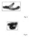
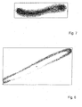
- the traces of movement are local have different brightnesses. This is because in the amplitudes the exciter oscillation the luminous dot lingers longer than an image pixel, as it is the case, for example, in the turning point of the periodic excitation oscillation is therefore experiencing a particularly dark picture.
- the Brightnesses of the motion track imaging image pixels can thus the local Speed determined within a periodic waveform become.
- the maximum deflection of the track z. B. in horizontal x and vertical y-direction using known image evaluation methods are determined.
- the maximum deflections ⁇ x max and ⁇ y max are parameters that can be compared with limit values. When a certain limit value for the set frequency of the excitation oscillation is exceeded, it is then detected in a test procedure that the object 3 assumes an impermissible state.
- the excitation frequency also other parameters, such as amplitude, acceleration, Speed etc. can be varied.
- amplitude, acceleration, Speed etc. can be varied.
- the control of the vibration generator 7 and the observation camera 10 can also by the evaluation 9 done.
- the mark with the cross points to the zero point of the Cartesian coordinate system out, preferably from the non-vibrating luminous point is determined.
- the width of a Trajectory should ideally go to zero.
- the influence of the track width is to be seen relative to the deflections. For torsional vibrations It may therefore be advantageous, a large screen and a large measuring distance to choose.
- the respective motion vector can now be used calculated at local positions of the moving track and from this the Track cross section determined and the ideal track to be generated.
- this procedure to its limits when the round trip of a deflection Overlaps shows and the entire vibration in a single Vibration pattern was detected, as in the present case. Then neither direction still track width can be determined from it.
- the ideal course of the moving track in dependence to determine the local brightness of the moving track. This exploits that the intensity of a movement track acts on the width, so to speak. A measuring point that radiates with constant brightness does not just get darker imaged as the speed of movement increases above the image pixels, but at the same time narrower. Unless for a constant track brightness Thus, the width of the moving track varies depending on their Brightness.
- a dormant spot is recorded while continuously the brightness of the luminous point from very dark to the whole is varied brightly. Because the luminous dot over the area of its picture no has constant brightness, the extreme value of its brightness or a mean brightness is used as a parameter and in a comparison table in Connection with an associated measured diameter of the luminous point to be recorded. In the evaluation of the motion track can then by Access to the comparison table for each measured brightness value determined Image width read and from the track width to the trigger to be brought.
- the local speed within the movement lane by evaluating the brightnesses of the periodic vibration mapping Image pixels to determine the motion track.
- the peripheral speed of the luminous point can be varied, for example by adjusting the offset or Divergenzwinkels a rotating laser, its exit beam to the axis of rotation has an offset or diverges.
- the respectively set Movement speed is then calculated from the circumference, the preferably derived directly from the measured pixel coordinates, and from the given angular frequency. In this way can be for each period duration or exposure time movement speeds and their associated Brightness of the luminous dots tab.
- Comparison table can then from the locally measured brightnesses of Luminous dots of any track and from the known exposure time the local movement speeds are derived.
- the brightness of the light spots and / or the brightness of the measurement mark 2 in a simple manner by measuring the of the image pixels of the observation camera 10 recorded amount of light to be regulated. With that you can previously poorly exposed portions of the track track worked out more Smooth, wide, overexposed portions of the track are smoothed become. In this case, however, is not a determination of the local speed more is possible.
- the measuring device according to FIG. 1 can be, for example used for vibration testing of vehicle headlights 11 be the defined vibrational excitations in the range of 10 to 60 Hertz, amplitudes of about 1 to 2 mm and accelerations of about 1 g get abandoned. This simulates vibration excitations that occur in the Normal operation, for example due to road bumps, wind forces, engine vibrations etc. are exerted on the vehicle headlights 11.
- These Vibration excitations can, especially if the vehicle headlights Control elements for a headlamp leveling and cornering have, to a lead undefined oscillation of the light cone. This shift of the light cone However, may only move within acceptable limits, with the inventive Measuring device can be checked.
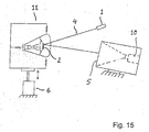
- FIG. 16 shows a sketch of a measuring device for determining the change in position the light-dark boundary of a light cone of a vehicle headlight detect.
- the calibration of the light cone to avoid glare is known to be with a projection screen and a camera that in low Distance (about 50 cm) from the vehicle headlight is positioned, where the setting is extrapolated to a projection distance of 10 m.
- the characteristic Light-dark boundary of the light cone consisting of two parallel to each other offset straight line pieces and a diagonal facing each other Ends of the straight sections connects.
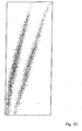
- the recorded motion track now consists not only of a point of light, but of the stepped Straight lines of the light cone and their displacement, so that in a long-term recording in the area of the displaced light cone a gray area in contrast to the white areas and black areas surrounding the gray area are created.
- the Width of the gray area can be evaluated directly as a vibration parameter become. However, overlap by sideways displacement of the line function the edges between the line and diagonal. To this yourself to better work out overlapping areas, the exposure time should be and exposure time and frame rate according to the location change to be controlled. Helpful for the evaluation is when the full Course of the light-dark border initially at the beginning by a shot in the Initial rest position is recorded and henceforth with methods of image processing best fit in the recordings, during the vibration be made. The respective layers of the cut-off line can then be clearly described by straight line equations and intersection coordinates, which need little data storage.
Landscapes
- Physics & Mathematics (AREA)
- General Physics & Mathematics (AREA)
- Length Measuring Devices By Optical Means (AREA)
- Measurement Of Mechanical Vibrations Or Ultrasonic Waves (AREA)
Applications Claiming Priority (2)
| Application Number | Priority Date | Filing Date | Title |
|---|---|---|---|
| DE10330946 | 2003-07-08 | ||
| DE2003130946 DE10330946B4 (de) | 2003-07-08 | 2003-07-08 | Verfahren zur Messung von Schwingungsvorgängen und Messeinrichtung hierzu |
Publications (1)
| Publication Number | Publication Date |
|---|---|
| EP1496343A2 true EP1496343A2 (fr) | 2005-01-12 |
Family
ID=33441674
Family Applications (1)
| Application Number | Title | Priority Date | Filing Date |
|---|---|---|---|
| EP20040016088 Withdrawn EP1496343A2 (fr) | 2003-07-08 | 2004-07-08 | Méthode et appareil pour l'enregistrement du mouvement des points de référence sur des structures vibrantes |
Country Status (2)
| Country | Link |
|---|---|
| EP (1) | EP1496343A2 (fr) |
| DE (1) | DE10330946B4 (fr) |
Cited By (11)
| Publication number | Priority date | Publication date | Assignee | Title |
|---|---|---|---|---|
| RU2447410C2 (ru) * | 2010-05-21 | 2012-04-10 | Ленинградская область, от имени которой выступает Государственное учреждение "Агентство экономического развития Ленинградской области" | Устройство для дистанционного измерения вибрационных параметров объекта |
| CN106338335A (zh) * | 2016-11-07 | 2017-01-18 | 西华大学 | 一种基于图像的轨枕振动在线监测方法 |
| CN106713733A (zh) * | 2015-11-17 | 2017-05-24 | 清华大学 | 一种记录物体运动信息的装置及方法 |
| CN108489695A (zh) * | 2018-03-21 | 2018-09-04 | 深圳市恒昱控制技术有限公司 | 振动模拟系统 |
| CN108593278A (zh) * | 2018-05-25 | 2018-09-28 | 中国人民解放军陆军工程大学 | 一种振动对光电设备成像质量影响试验分析系统 |
| CN110501179A (zh) * | 2019-09-11 | 2019-11-26 | 宝钜(中国)儿童用品有限公司 | 电动安抚椅运动状态测试装置及测试方法 |
| CN112461465A (zh) * | 2020-10-09 | 2021-03-09 | 天津大学 | 基于偏振成像的mems面内振动特性的测量方法 |
| CN114427904A (zh) * | 2021-12-21 | 2022-05-03 | 珠海格力电器股份有限公司 | 振动检测方法以及振动检测装置 |
| CN115096429A (zh) * | 2022-08-24 | 2022-09-23 | 山东科尔自动化仪表股份有限公司 | 一种振动测量装置及方法 |
| CN118224999A (zh) * | 2024-05-24 | 2024-06-21 | 华东交通大学 | 一种基于结构光的钢轨磨耗识别方法及设备 |
| EP4471389A1 (fr) * | 2023-05-31 | 2024-12-04 | B&R Industrial Automation GmbH | Procédé et dispositif de détermination d'amplitude pour systèmes de transport par vibrations |
Families Citing this family (2)
| Publication number | Priority date | Publication date | Assignee | Title |
|---|---|---|---|---|
| DE102006039536A1 (de) * | 2006-08-23 | 2008-03-13 | Deutsches Zentrum für Luft- und Raumfahrt e.V. | Verfahren zur Modalanalyse einer harmonisch angeregten elastomechanischen Struktur |
| DE102024128592B3 (de) * | 2024-10-02 | 2026-02-19 | Bayerische Motoren Werke Aktiengesellschaft | Verfahren zum Erkennen eines Betriebszustands einer Fahrzeugkomponente eines Kraftfahrzeuges, Computerprogramm und/oder computerlesbares Medium, Datenverarbeitungsvorrichtung und Kraftfahrzeug |
Family Cites Families (7)
| Publication number | Priority date | Publication date | Assignee | Title |
|---|---|---|---|---|
| US4899218A (en) * | 1987-02-18 | 1990-02-06 | Perceptron, Inc. | Vehicle wheel alignment apparatus and method |
| US5023845A (en) * | 1988-10-31 | 1991-06-11 | The United States Of America As Represented By The Secretary Of The Navy | Embedded fiber optic beam displacement sensor |
| JPH0599736A (ja) * | 1991-10-09 | 1993-04-23 | Meidensha Corp | 残像による周波数分析方法 |
| DE4212426C1 (en) * | 1992-04-14 | 1993-07-01 | Wolfgang 3407 Gleichen De Brunk | Measurement of tracking and camber of vehicle wheel axles - recording markers on rotating wheels using synchronised video cameras, image evaluation of marker positions |
| US6317506B1 (en) * | 1999-04-15 | 2001-11-13 | The United States Of America As Represented By The Secretary Of The Air Force | Measuring the characteristics of oscillating motion |
| JP2002267577A (ja) * | 2001-03-13 | 2002-09-18 | Mazda Motor Corp | 自動車のサスペンション挙動計測装置 |
| WO2006036591A1 (fr) | 2004-09-24 | 2006-04-06 | Eveready Battery Company, Inc. | Instrument de rasage utilisant des sections de cartouche separees |
-
2003
- 2003-07-08 DE DE2003130946 patent/DE10330946B4/de not_active Expired - Fee Related
-
2004
- 2004-07-08 EP EP20040016088 patent/EP1496343A2/fr not_active Withdrawn
Cited By (11)
| Publication number | Priority date | Publication date | Assignee | Title |
|---|---|---|---|---|
| RU2447410C2 (ru) * | 2010-05-21 | 2012-04-10 | Ленинградская область, от имени которой выступает Государственное учреждение "Агентство экономического развития Ленинградской области" | Устройство для дистанционного измерения вибрационных параметров объекта |
| CN106713733A (zh) * | 2015-11-17 | 2017-05-24 | 清华大学 | 一种记录物体运动信息的装置及方法 |
| CN106338335A (zh) * | 2016-11-07 | 2017-01-18 | 西华大学 | 一种基于图像的轨枕振动在线监测方法 |
| CN108489695A (zh) * | 2018-03-21 | 2018-09-04 | 深圳市恒昱控制技术有限公司 | 振动模拟系统 |
| CN108593278A (zh) * | 2018-05-25 | 2018-09-28 | 中国人民解放军陆军工程大学 | 一种振动对光电设备成像质量影响试验分析系统 |
| CN110501179A (zh) * | 2019-09-11 | 2019-11-26 | 宝钜(中国)儿童用品有限公司 | 电动安抚椅运动状态测试装置及测试方法 |
| CN112461465A (zh) * | 2020-10-09 | 2021-03-09 | 天津大学 | 基于偏振成像的mems面内振动特性的测量方法 |
| CN114427904A (zh) * | 2021-12-21 | 2022-05-03 | 珠海格力电器股份有限公司 | 振动检测方法以及振动检测装置 |
| CN115096429A (zh) * | 2022-08-24 | 2022-09-23 | 山东科尔自动化仪表股份有限公司 | 一种振动测量装置及方法 |
| EP4471389A1 (fr) * | 2023-05-31 | 2024-12-04 | B&R Industrial Automation GmbH | Procédé et dispositif de détermination d'amplitude pour systèmes de transport par vibrations |
| CN118224999A (zh) * | 2024-05-24 | 2024-06-21 | 华东交通大学 | 一种基于结构光的钢轨磨耗识别方法及设备 |
Also Published As
| Publication number | Publication date |
|---|---|
| DE10330946A1 (de) | 2005-02-10 |
| DE10330946B4 (de) | 2005-09-22 |
Similar Documents
| Publication | Publication Date | Title |
|---|---|---|
| EP2223751B1 (fr) | Méthode pour reconnaître une structure appliqué sur un substrat avec une pluralité de caméras et un appareil pour executer ladite methode. | |
| EP1290626B1 (fr) | Unite de positionnement | |
| EP0774646B1 (fr) | Procédé et dispositif pour vérifier l'alignement des axes et des roues de voitures automobiles | |
| DE10330946B4 (de) | Verfahren zur Messung von Schwingungsvorgängen und Messeinrichtung hierzu | |
| EP2609395B1 (fr) | Capteur d'inclinaison pour un appareil et procédé de détermination de l'inclinaison d'un appareil | |
| DE102016011801A1 (de) | Verfahren zum Kalibrieren einer Vorrichtung zum Herstellen eines dreidimensionalen Objekts und zum Durchführen des Verfahrens ausgebildete Vorrichtung | |
| EP3479061B1 (fr) | Procédé de comparaison d'un faisceau de réception se produisant sur un récepteur laser avec un faisceau laser rotatif | |
| DE112015000349T5 (de) | Bildprojektionsvorrichtung und Einstellverfahren und Steuerverfahrenfür eine Bildprojektionsvorrichtung | |
| EP2801789A1 (fr) | Dispositif de détermination de la position d'éléments mécaniques | |
| WO2007080014A1 (fr) | Procédé de mesure optique de châssis | |
| DE60204495T2 (de) | Linsenmesser zur Messung der Eigenschaft eines Brillenglases oder einer Kontaktlinse | |
| DE102016115277A1 (de) | Optische Vorrichtung | |
| DE102020215420A1 (de) | Verfahren zum Kalibrieren mindestens einer Kamera | |
| DE102006019840B4 (de) | Zeilenkamera für spektrale Bilderfassung | |
| DE10223923B4 (de) | Verfahren und Anordnung zur fotografischen Aufnahme eines Fahrzeuges | |
| DE102009024961A1 (de) | Verfahren und Vorrichtung zur Bewertung von Scheinwerfern | |
| WO2017162329A1 (fr) | Procédé et dispositif pour déterminer les coordonnées 3d d'au moins un point prédéterminée d'un objet | |
| DE10225006A1 (de) | Verfahren zur Erfassung der Oberfläche einer Fahrbahn | |
| DE3634724A1 (de) | Verfahren und vorrichtung zum beruehrungslosen optischen messen von wegen, insbesondere im triangulationsverfahren | |
| DE10063786A1 (de) | Vorrichtung und Verfahren zum Vermessen eines Gegenstandes | |
| DE10256725B3 (de) | Sensor, Vorrichtung und Verfahren zur Geschwindigkeitsmessung | |
| DE4226661A1 (de) | Verfahren und Vorrichtung zur Bedienung elektronischer Musikinstrumente | |
| EP0867689A2 (fr) | Dispositif de mesure microphotogrammétrique | |
| DE3016878C2 (de) | Verfahren zum berührungslosen optischen Empfang von Ultraschallwellen | |
| DE102013210736A1 (de) | Vorrichtung zum Ermitteln der Lage von mechanischen Elementen |
Legal Events
| Date | Code | Title | Description |
|---|---|---|---|
| PUAI | Public reference made under article 153(3) epc to a published international application that has entered the european phase |
Free format text: ORIGINAL CODE: 0009012 |
|
| AK | Designated contracting states |
Kind code of ref document: A2 Designated state(s): AT BE BG CH CY CZ DE DK EE ES FI FR GB GR HU IE IT LI LU MC NL PL PT RO SE SI SK TR |
|
| AX | Request for extension of the european patent |
Extension state: AL HR LT LV MK |
|
| STAA | Information on the status of an ep patent application or granted ep patent |
Free format text: STATUS: THE APPLICATION IS DEEMED TO BE WITHDRAWN |
|
| 18D | Application deemed to be withdrawn |
Effective date: 20080201 |