EP1496352B1 - Procédé et dispositif pour surveiller la température d'une structure physique - Google Patents
Procédé et dispositif pour surveiller la température d'une structure physique Download PDFInfo
- Publication number
- EP1496352B1 EP1496352B1 EP03077168A EP03077168A EP1496352B1 EP 1496352 B1 EP1496352 B1 EP 1496352B1 EP 03077168 A EP03077168 A EP 03077168A EP 03077168 A EP03077168 A EP 03077168A EP 1496352 B1 EP1496352 B1 EP 1496352B1
- Authority
- EP
- European Patent Office
- Prior art keywords
- physical structure
- temperature
- concrete
- measured temperatures
- points
- Prior art date
- Legal status (The legal status is an assumption and is not a legal conclusion. Google has not performed a legal analysis and makes no representation as to the accuracy of the status listed.)
- Expired - Lifetime
Links
Images
Classifications
-
- G—PHYSICS
- G01—MEASURING; TESTING
- G01N—INVESTIGATING OR ANALYSING MATERIALS BY DETERMINING THEIR CHEMICAL OR PHYSICAL PROPERTIES
- G01N25/00—Investigating or analyzing materials by the use of thermal means
- G01N25/18—Investigating or analyzing materials by the use of thermal means by investigating thermal conductivity
-
- G—PHYSICS
- G01—MEASURING; TESTING
- G01N—INVESTIGATING OR ANALYSING MATERIALS BY DETERMINING THEIR CHEMICAL OR PHYSICAL PROPERTIES
- G01N33/00—Investigating or analysing materials by specific methods not covered by groups G01N1/00 - G01N31/00
- G01N33/38—Concrete; Lime; Mortar; Gypsum; Bricks; Ceramics; Glass
- G01N33/383—Concrete or cement
Definitions
- the invention relates to a method according to the preamble of claim 1.
- the invention also relates to an arrangement according to the preamble of claim 14.
- Thermoelement sensors are traditional means for measuring temperature of a concrete structure during the hardening phase.
- a more recent trend has been the use of optical fibre sensors in temperature measurements.
- Optical fibres are commonly used for data communications, but they can be employed also as temperature measurement sensors.
- Optical sensors have several advantages in comparison with electronic sensors, such as thermoelement sensors. They can be applied under adverse environmental conditions as well as at high temperatures.
- Thermoelement sensors are well suited for single-point measurements, but optical fibre sensors suit better for obtaining information about temperature differences and distribution within structures, since they effectively register temperatures over their whole length. For example a 50 m long optical fibre can be considered to correspond 50-200 thermoelement sensors. Especially in large and/or complicated massive structures the use of optical fibre sensors is thus advantageous.
- document EP 0 572 238 B1 describes a method of monitoring temperature and condition of a blast furnace by means of optical fibre sensors and document EP 0 555 846 A2 describes a structure for detecting temperature abnormality in a fluid pipe.
- a method of detecting fluid leaks in a dumpsite, using a meandering cable that comprises an optical fibre temperature sensor and a thermal cable, is described in EP 0672903 .
- Grouting is a method of constructing concrete, wherein prestressing steel is placed into a duct within a concrete structure and concrete is grouted into the duct to fill the space between the prestressing steel and the duct.
- the space between the prestressing steel and the duct should be fully filled, but sometimes there are holes or coarse areas or a so called rock pocket in there, which may weaken the concrete structure. It is difficult to detect these holes or coarse areas by means of prior art methods and therefore a new method is needed.
- An object of the invention is to improve monitoring the condition of a substantially homogenous physical structure, such as an earth construction, an earth filled dam, structures of a district heating network, or a building structure, such as a structure made of concrete or conductive concrete.
- the invention is based on using variation of heat distribution in a physical structure for detecting defects and/or non-homogeneity in the structure. For example thermal conductivities of wet and dry structures are different and thermal conductivities of a structure with cracks or spalls and an unbroken structure are different.
- an embodiment of the invention provides an improved method for monitoring physical structures and that structures can be monitored over their whole lifecycle. Also the condition of structures, which are already in use, can be analysed. In principle, monitoring can be continuous, that is, measurements are repeated periodically, or the measurements can be done only when they are considered necessary. Moreover, providing a timely and relatively accurate estimate of damages in physical structures is enabled.
- temperature measurements may have been used for identifying defects in a structure.
- the temperature of the structure may have been changed in order to minimize the defect.
- the invention provides a method, wherein changing the temperature of the structure is part of the method of monitoring the condition of the structure. Nevertheless, the method of the invention does not prevent using an additional change of temperature for minimizing defects detected in the structure.
- Optical fibre comprises a core and a cladding made of glass having different refraction indexes.
- the function of an optical fibre is based on the refraction and reflection of light in the interface of the core and the cladding.
- the fibre and cabling of the fibre are selected so that environment affects transferred data as little as possible.
- the selection of materials is such that the variable to be measured has a controlled effect on the light travelling in the fibre. Then, changes in light intensity, phase, wavelength or polarisation can be used for determining the value of the variable to be measured.
- a temperature measurement by means of an optical fibre sensor employs for example analysing Raman backscattered signals caused when a laser pulse is travelling in the optical fibre.
- a short laser pulse is sent into the optical fibre from one end of the fibre.
- anti-Stokes and Stokes photons are generated along the fibre.
- a fraction of these scattered photons propagate back and are detected by a photodetector.
- the generation of anti-Stokes photons is sensitive to the temperature of the environment. Therefore, by means of analysing the backscattered Stokes and anti-Stokes photons, the temperature along the fibre can be calculated.
- the point of the optical fibre in which a certain temperature value was measured can be identified on the basis of the speed of light and the time between sending the light pulse and detecting the backscattered photons.
- the light pulse is sent repeatedly and the repetition frequency is selected so that backscattered signals originated from different light pulses do not mix up.
- the accuracy of temperature measurement results along the length of the optical fibre depends on the characteristics of the fibre, but in any case an optical fibre sensor can be considered to be a full-length sensor.
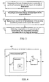
- Figure 1 is a flow diagram illustrating a method according to the invention for monitoring the condition of a substantially homogenous physical structure. It is assumed that an optical fibre temperature sensor is cast or buried into the physical structure or fitted on the surface of it in order to measure temperature of the physical structure. Preferably, the optical fibre is assembled so that temperature is measured over the full length of the structure or over a desired two- or three-dimensional plane of the structure.
- a first set of temperatures is measured in a plurality of points of the physical structure by means of the optical fibre sensor.
- the optical fibre sensor can be considered to be a full-length sensor, the points in which temperature is measured may be in fact next to each other.
- a controlled change of temperature is caused in said physical structure.
- the physical structure is heated, but equally it can be cooled down.
- the change of temperature can be caused for example by means of a thermal cable assembled in proximity of the optical fibre sensor.
- the use of thermal cables is further discussed below in connection with Figure 3 .
- the physical structure is conductive (for example conductive concrete)
- heat can be conveyed into the structure by means of its conductivity. In that case it is enough to attach heating electrodes on the surface of the physical structure and the conductivity of the structure takes care of distributing the heat inside the structure.
- Still other possibility is to use hot- or cold-liquid pipeline inside the structure for causing the change of temperature.
- a second set of temperatures are measured in the plurality of points of the physical structure by means of the optical fibre sensor and in step 13 the second set of temperatures is analysed and irregularities in the temperatures are detected, the irregularities indicating at least one discontinuity in the physical structure.
- the physical structure to be monitored is substantially homogenous in normal circumstances, heat should be somewhat evenly distributed in the structure. If heat is not distributed evenly, it can be assumed that there is some defect or discontinuity in the structure.
- Such discontinuity or defect may be for example a hole, a coarse area, a rock pocket, entrapped air, a crack, a spall, honeycombing, a frozen area, moisture, a leakage, a bend, or a dislocation in the physical structure, a foreign object within the structure, or running fluid inside or on the surface of the physical structure. Therefore, according to certain embodiments of the invention, the method of monitoring the condition of a substantially homogenous physical structure is used for detecting and/or locating honeycombing in a concrete structure and/or for analysing grouting quality in a concrete structure.
- discontinuities in the structure can be detected by calculating difference in the temperature of in various points of the structure before and after changing the temperature and by detecting variation in the temperature difference between different points. That is, a difference between the first and second sets of measured temperatures is calculated.
- a relatively large or small temperature difference in some point indicates non-homogeneity of the structure or a defect in the structure in that point.
- magnitude of the controlled change of temperature may be different in different parts of the physical structure. However, in that case the differences in the change of temperature need to be taken into account in analysing measured temperatures.
- heating the structure and temperature measurements can be repeated and/or they can both be continuous and/or the heating magnitude may be changed. This way, for example, changes in the structure over a certain time period can be identified. For example, if there is moisture in the structure, heating should evaporate the moisture. Thus a continuous leak in the structure can be distinguished from occasional moisture by detecting, if the heating dries the structure. Different heating magnitudes and different lengths of the heating time can be used for analysing the extent of a leakage in the structure. Also the temperature of the environment can be taken into account in analysing different temperatures of the structure.
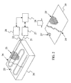
- FIG. 2 illustrates an arrangement according to an embodiment of the invention.
- the Figure 2 shows a cross sectional view of the concrete structure showing an optical fibre sensor 21, which has been assembled into the concrete structure.
- the optical fibre sensor is bent to cover a cross sectional plane of the concrete structure so that a temperature versus a location chart over the cross sectional plane can be obtained by means of the optical fibre sensor.
- the optical fibre sensor 21 is coupled to a temperature measurement unit 27, which is adapted to send a light pulse into the optical fibre sensor and to detect and analyse backscattered light from the sensor for determining temperature in different points of the concrete structure.
- the temperature measurement unit 27 preferably comprises a source of light and a detector (not shown), which are functionally coupled to the optical fibre, and a signal processor (not shown) for providing the temperature measurement results.
- a thermal cable 22 is assembled next to the optical fibre sensor within the concrete structure 20.
- the thermal cable is coupled to a temperature-controlling unit 26, which is adapted to send a heat pulse into the thermal cable in order to cause a change of temperature in the concrete.
- the temperature measurement unit 27 and the temperature-controlling unit 26 are both functionally coupled to a computing device 28, which comprises analysing means for analysing temperature measurement results obtained from the temperature measurement unit 27.
- These analysing means are preferably implemented as a suitable combination of hardware and software components; for example as a processing unit and a computer program code executable in the processing unit.
- the analysing means produce and output a two-dimensional chart 29 over the cross sectional plane of the differences in the temperatures before and after heating the concrete structure.
- the areas 23', 24' and 25', where the differences in the temperatures are relatively large or small are shaded in the chart 29.
- the shading 23' indicates a spall 23 in the concrete
- the shading 24' indicates a crack 24
- the shading 25' indicates a wet area 25.
- the computing device 28 also controls the temperature measurement unit 27 and the temperature-controlling unit 26 in order to set the timing of temperature measurements and heating as desired.
- the thermal cable 22 can be replaced with heating electrodes, which are attached to the surface of the structure. Conductivity of the structure then conveys the heat within the structure and differences in heat distribution indicating defects in the structure can be detected by measuring the temperature by means of the optical fibre sensor as described above.
- the controlled change of temperature in the physical structure may be caused for example by means of a thermal cable, which is beforehand assembled substantially in proximity of the optical fibre sensor.
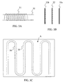
- Figures 3A-3C illustrate by way of example certain preferred ways for assembling a thermal cable in proximity of an optical fibre sensor.
- a thermal cable 31 has been wound around an optical fibre sensor 30, and in Figure 3B two parallel thermal cables 33a and 33b have been fitted next to an optical fibre sensor 32 onto opposite sides of the sensor.
- an optical fibre sensor 34 has been bent to effectively cover an area A in a two-dimensional plane and a thermal cable 35 has been bent into the same form with the optical fibre sensor and fitted next to the sensor.
- any one of these assemblies can be cast or buried into the physical structure or fitted on the surface of the physical structure; the former concerning especially assemblies during the construction of the structure and the latter concerning mainly assemblies after the construction of the structure.
- a thermal cable can be assembled in any other suitable way, too.
- Figure 4 illustrates by way of example a simplified block diagram of a device 40 that can be used in the invention, which device 40 may be for example a general-purpose computer or some other suitable computing device.
- the device 40 comprises a processing unit 41 comprising memory 43.
- the processing unit is functionally coupled to an I/O interface 42, through which the device 40 communicates with other devices.
- a computer program 44 to be executed in the processing unit 41 is stored in the memory 43.
- the computer program 44 comprises program code for controlling temperature measurement means comprising an optical fibre sensor and controlling means for causing a change of temperature, such as the temperature measurement unit 26 and the temperature-controlling unit 27 shown in Figure 2 .
- the computer program 44 controls the temperature measurement means to obtain a set of first measured temperature values for a plurality of points in a physical structure, the temperature-controlling means to cause a controlled change of temperature in the physical structure, and again the temperature measurement means to obtain a set of second measured temperature values for a plurality of points in the physical structure after the controlled change of temperature has been induced into the physical structure.
- the computer program comprises program code for detecting irregularities in the second measured values, while the irregularities indicate discontinuities, such as holes, coarse areas, moisture or some other defect, in said physical structure.
- the computer program may comprise also program code for outputting a graphical representation indicating the discontinuities detected in the physical structure. Further, the computer program may calculate, for the plurality of points in which the temperature is measured, difference between the sets of first and second measured temperature values. Variation in this difference between the plurality of points then indicates the irregularities and thereby the discontinuities in the physical structure.
Landscapes
- Chemical & Material Sciences (AREA)
- Health & Medical Sciences (AREA)
- Life Sciences & Earth Sciences (AREA)
- Immunology (AREA)
- Analytical Chemistry (AREA)
- Biochemistry (AREA)
- General Health & Medical Sciences (AREA)
- General Physics & Mathematics (AREA)
- Physics & Mathematics (AREA)
- Pathology (AREA)
- Engineering & Computer Science (AREA)
- Ceramic Engineering (AREA)
- Food Science & Technology (AREA)
- Medicinal Chemistry (AREA)
- Measuring Temperature Or Quantity Of Heat (AREA)
- Investigating Or Analyzing Materials Using Thermal Means (AREA)
- Radiation Pyrometers (AREA)
Claims (14)
- Procédé de surveillance de l'état d'une structure physique sensiblement homogène (20), ledit procédé comprenant les étapes suivantes :- la mesure (10) d'une température de ladite structure physique au moyen d'un capteur à fibres optiques (21, 30, 32, 34) pour obtenir un ensemble de températures mesurées en une pluralité de points de ladite structure physique,- le changement contrôlé (11) de la température dans ladite structure physique au moyen d'un câble thermique (22, 31, 33a, 33b, 35) assemblé à proximité de ladite fibre optique (21, 30, 32, 34), ledit changement contrôlé de température étant uniforme sur ladite structure physique,- la détection (13) d'irrégularités dans lesdites températures mesurées, lesdites irrégularités indiquant au moins une discontinuité dans ladite structure physique, ladite détection desdites irrégularités étant caractérisée par les étapes suivantes :- l'obtention pour ladite pluralité de points d'un premier ensemble de températures mesurées (10) avant ledit changement contrôlé de température et d'un second ensemble de températures mesurées (12) après ledit changement contrôlé de température,- le calcul, pour ladite pluralité de points, d'une différence entre ledit premier ensemble de températures mesurées et ledit second ensemble de températures mesurées, et- la détection d'une variation dans ladite différence entre ladite pluralité de points, ladite variation indiquant ladite au moins une discontinuité dans ladite structure physique.
- Procédé selon la revendication 1, dans lequel l'amplitude dudit changement contrôlé de température varie sur ladite structure physique et ladite variation de l'amplitude est prise en compte dans la détection desdites irrégularités.
- Procédé selon la revendication 1 ou 2, dans lequel ladite structure physique est faite de béton ou de béton conducteur.
- Procédé selon la revendication 3, dans lequel ledit procédé est utilisé pour détecter et/ou localiser des nids de graviers dans le béton ou le béton conducteur et/ou pour analyser la qualité de la cimentation du béton ou du béton conducteur.
- Procédé selon la revendication 1 ou 2, dans lequel ladite structure physique est une structure d'un réseau de chauffage urbain.
- Procédé selon la revendication 1 ou 2, dans lequel ladite structure physique est faite de béton conducteur et ledit changement contrôlé de température est effectué au moyen des parties conductrices du béton.
- Procédé selon la revendication 1 ou 2, dans lequel ladite structure physique est une construction en terre.
- Procédé selon la revendication 1 ou 2, dans lequel ladite structure physique est un barrage en terre.
- Procédé selon l'une quelconque des revendications 1 à 8, dans lequel ladite discontinuité est l'une des suivantes : un trou, une zone à gros grains, un nid de cailloux, une inclusion d'air, une fissure, un éclat, un nid de graviers, une zone congelée, de l'humidité, une fuite, une courbure ou une dislocation dans la structure physique, un objet étranger à l'intérieur de la structure, ou un fluide en mouvement à l'intérieur ou sur la surface de la structure physique.
- Procédé selon l'une quelconque des revendications 1 à 9, dans lequel ledit procédé est utilisé pour surveiller l'état de la structure physique après que la construction de ladite structure physique a été terminée.
- Procédé selon l'une quelconque des revendications 1 à 10, dans lequel ledit procédé est utilisé pour surveiller l'état de la structure physique pendant l'utilisation normale de ladite structure physique.
- Procédé selon l'une quelconque des revendications 1 à 11, dans lequel l'amplitude dudit changement contrôlé de température est prédéterminée.
- Procédé selon l'une quelconque des revendications 1 à 12, dans lequel l'amplitude dudit changement contrôlé de température est indépendante des résultats de mesure de température.
- Agencement pour surveiller l'état d'une structure physique sensiblement homogène (20), comprenant :- des moyens de mesure de température (27) comprenant un capteur à fibres optiques (21, 30, 32, 34) pour mesurer la température de ladite structure physique pour obtenir un ensemble de températures mesurées en une pluralité de points de ladite structure physique,- un câble thermique (22, 31, 33a, 33b, 35) assemblé à proximité de ladite fibre optique (21, 30, 32, 34) pour provoquer un changement contrôlé de température dans ladite structure physique,- ledit câble thermique (22, 31, 33a, 33b, 35) étant couplé à une unité de régulation de la température (26) qui est adaptée pour envoyer une impulsion thermique dans le câble thermique (22, 31, 33a, 33b, 35) pour provoquer un changement de température dont l'amplitude est uniforme sur ladite structure physique,- des moyens (28) pour détecter des irrégularités dans lesdites températures mesurées, lesdites irrégularités indiquant au moins une discontinuité dans ladite structure physique,- lesdits moyens (28) pour détecter lesdites irrégularités étant caractérisés en ce qu'ils sont adaptés pour :- obtenir, pour ladite pluralité de points, un premier ensemble de températures mesurées avant ledit changement contrôlé de température et un second ensemble de températures mesurées après ledit changement contrôlé de température,- calculer, pour ladite pluralité de points, une différence entre ledit premier ensemble de températures mesurées et ledit second ensemble de températures mesurées, et- détecter une variation dans ladite différence entre ladite pluralité de points, ladite variation indiquant ladite au moins une discontinuité dans ladite structure physique.
Priority Applications (3)
| Application Number | Priority Date | Filing Date | Title |
|---|---|---|---|
| AT03077168T ATE471510T1 (de) | 2003-07-10 | 2003-07-10 | Verfahren und vorrichtung zur temperaturüberwachung einer physikalischen struktur |
| DE60333006T DE60333006D1 (de) | 2003-07-10 | 2003-07-10 | Verfahren und Vorrichtung zur Temperaturüberwachung einer physikalischen Struktur |
| EP03077168A EP1496352B1 (fr) | 2003-07-10 | 2003-07-10 | Procédé et dispositif pour surveiller la température d'une structure physique |
Applications Claiming Priority (1)
| Application Number | Priority Date | Filing Date | Title |
|---|---|---|---|
| EP03077168A EP1496352B1 (fr) | 2003-07-10 | 2003-07-10 | Procédé et dispositif pour surveiller la température d'une structure physique |
Publications (2)
| Publication Number | Publication Date |
|---|---|
| EP1496352A1 EP1496352A1 (fr) | 2005-01-12 |
| EP1496352B1 true EP1496352B1 (fr) | 2010-06-16 |
Family
ID=33442810
Family Applications (1)
| Application Number | Title | Priority Date | Filing Date |
|---|---|---|---|
| EP03077168A Expired - Lifetime EP1496352B1 (fr) | 2003-07-10 | 2003-07-10 | Procédé et dispositif pour surveiller la température d'une structure physique |
Country Status (3)
| Country | Link |
|---|---|
| EP (1) | EP1496352B1 (fr) |
| AT (1) | ATE471510T1 (fr) |
| DE (1) | DE60333006D1 (fr) |
Families Citing this family (11)
| Publication number | Priority date | Publication date | Assignee | Title |
|---|---|---|---|---|
| EP2386849A1 (fr) | 2010-05-10 | 2011-11-16 | Fortum OYJ | Procédé, appareil et produit de programme informatique pour mesurer l'état d'une structure en béton |
| KR101254293B1 (ko) * | 2011-09-08 | 2013-04-12 | 이재준 | 스마트 기능을 보유한 지능형 히팅 케이블 및 그 제조방법 |
| JP6203142B2 (ja) * | 2014-07-03 | 2017-09-27 | 三菱電機株式会社 | ハニカムサンドイッチ構造体およびその製造方法 |
| CN108051629B (zh) * | 2017-11-28 | 2024-07-12 | 法泰电器(江苏)股份有限公司 | 一种断路器用负载电流监视装置 |
| CN107748179B (zh) * | 2017-12-05 | 2020-05-22 | 湖北工业大学 | 一种基于dts检测灌注桩完整性光纤加热影响半径确定方法 |
| CN108612058B (zh) * | 2018-04-08 | 2020-05-12 | 三峡大学 | 一种混凝土坝分布式测温光纤双股“z字形”通仓埋设施工方法 |
| CN109822719A (zh) * | 2019-01-23 | 2019-05-31 | 南京理工大学 | 一种在混凝土中埋设双端fbg传感器的方法 |
| CN110512608A (zh) * | 2019-09-18 | 2019-11-29 | 上海建工二建集团有限公司 | 基于分布式光纤的混凝土抗裂装置与方法 |
| KR102421526B1 (ko) * | 2020-07-13 | 2022-07-15 | 아이엠(주) | 반응로 후드의 파열 예방과 수관의 누수 감지를 위한 후드 외관 구조 및 감지장치 |
| CN112922050A (zh) * | 2021-02-01 | 2021-06-08 | 上海建工二建集团有限公司 | 基桩完整性检测方法及装置 |
| CN112859201B (zh) * | 2021-03-15 | 2022-10-25 | 张馨予 | 一种用于农业物联网的便携式气象监测装置 |
Family Cites Families (4)
| Publication number | Priority date | Publication date | Assignee | Title |
|---|---|---|---|---|
| FR2559262B1 (fr) * | 1984-02-07 | 1990-03-02 | France Etat | Procede et dispositif de controle non destructif dans une structure en masse |
| DE3626354A1 (de) * | 1986-08-04 | 1988-02-11 | Poellinger Wolfgang Dipl Ing F | Verfahren zur lokalisierung von unsichtbaren abloesungen und rissbildungen in betonkonstruktionen |
| CA1305769C (fr) * | 1986-11-04 | 1992-07-28 | Nobuyuki Yamazaki | Methode de prevision et de mesure du developpement de la resistance du beton, et appareil connexe |
| US20020018510A1 (en) * | 1996-07-31 | 2002-02-14 | Murphy John C. | Thermal-based methods for nondestructive evaluation |
-
2003
- 2003-07-10 EP EP03077168A patent/EP1496352B1/fr not_active Expired - Lifetime
- 2003-07-10 DE DE60333006T patent/DE60333006D1/de not_active Expired - Lifetime
- 2003-07-10 AT AT03077168T patent/ATE471510T1/de not_active IP Right Cessation
Also Published As
| Publication number | Publication date |
|---|---|
| EP1496352A1 (fr) | 2005-01-12 |
| DE60333006D1 (de) | 2010-07-29 |
| ATE471510T1 (de) | 2010-07-15 |
Similar Documents
| Publication | Publication Date | Title |
|---|---|---|
| Tan et al. | Detection, visualization, quantification, and warning of pipe corrosion using distributed fiber optic sensors | |
| Zheng et al. | Experimental research on a novel optic fiber sensor based on OTDR for landslide monitoring | |
| CN102384725B (zh) | 隧道收敛变形分布式光纤监测方法及系统 | |
| Culshaw et al. | Smart structures and applications in civil engineering | |
| Failleau et al. | A metrological comparison of Raman-distributed temperature sensors | |
| CN115389066B (zh) | 一种基于分布式光纤光栅感测的桥梁健康监测系统 | |
| Herbers et al. | Rayleigh-based crack monitoring with distributed fiber optic sensors: experimental study on the interaction of spatial resolution and sensor type | |
| CN105157999B (zh) | 基于分布式光纤传感技术桩完整性和横向位移的评估方法 | |
| WO2014056541A1 (fr) | Procédé permettant de surveiller l'érosion des sols autour de dispositifs enfouis, dispositif instrumenté et système permettant de réaliser le procédé | |
| Cao et al. | Performance evaluation of two types of heated cables for distributed temperature sensing-based measurement of soil moisture content | |
| EP1496352A1 (fr) | Procédé et dispositif pour surveiller la température d'une structure physique | |
| Bergmeister et al. | Global monitoring concepts for bridges | |
| US20230221195A1 (en) | Distributed continuous high-accuracy bidirectional displacement fiber-optic measurement system and measurement method thereof | |
| Liu et al. | Pipeline safety monitoring technology based on FBG-ROTDR joint system and its case study of urban drainage pipeline monitoring | |
| CN119164310A (zh) | 一种多级高陡道路边坡分布式光纤变形监测方法 | |
| CN116026419A (zh) | 一种基于分布式光纤的埋地管线挠度和受力方向预测方法 | |
| CN221502082U (zh) | 一种光纤式基桩热分析检测装置 | |
| Zhao et al. | Crack width measurement with OFDR distributed fiber optic sensors considering strain redistribution after structure cracking | |
| Bernini et al. | Identification of defects and strain error estimation for bending steel beams using time domain Brillouin distributed optical fiber sensors | |
| CN108612058A (zh) | 一种混凝土坝分布式测温光纤双股“z字形”通仓埋设施工方法 | |
| Guo et al. | Fiber Bragg grating sensor-based monitoring strategy for slope deformation in centrifugal model test | |
| Zhu et al. | Rayleigh scattering based, thermal-induced displacement measurement along a steel plate at high temperature | |
| RU2428682C1 (ru) | Способ теплового неразрушающего контроля теплотехнического состояния протяженных, сложнопрофильных и труднодоступных объектов | |
| Li et al. | Combined interrogation using an encapsulated FBG sensor and a distributed Brillouin tight buffered fiber sensor in a Tunnel | |
| CN210603213U (zh) | 基于光纤感测技术的受力杆件压缩和拉伸变形的监测装置 |
Legal Events
| Date | Code | Title | Description |
|---|---|---|---|
| PUAI | Public reference made under article 153(3) epc to a published international application that has entered the european phase |
Free format text: ORIGINAL CODE: 0009012 |
|
| AK | Designated contracting states |
Kind code of ref document: A1 Designated state(s): AT BE BG CH CY CZ DE DK EE ES FI FR GB GR HU IE IT LI LU MC NL PT RO SE SI SK TR |
|
| AX | Request for extension of the european patent |
Extension state: AL LT LV MK |
|
| 17P | Request for examination filed |
Effective date: 20050520 |
|
| AKX | Designation fees paid |
Designated state(s): AT BE BG CH CY CZ DE DK EE ES FI FR GB GR HU IE IT LI LU MC NL PT RO SE SI SK TR |
|
| AXX | Extension fees paid |
Extension state: LV Payment date: 20050520 |
|
| GRAP | Despatch of communication of intention to grant a patent |
Free format text: ORIGINAL CODE: EPIDOSNIGR1 |
|
| GRAS | Grant fee paid |
Free format text: ORIGINAL CODE: EPIDOSNIGR3 |
|
| GRAA | (expected) grant |
Free format text: ORIGINAL CODE: 0009210 |
|
| AK | Designated contracting states |
Kind code of ref document: B1 Designated state(s): AT BE BG CH CY CZ DE DK EE ES FI FR GB GR HU IE IT LI LU MC NL PT RO SE SI SK TR |
|
| AX | Request for extension of the european patent |
Extension state: LV |
|
| REG | Reference to a national code |
Ref country code: CH Ref legal event code: EP |
|
| REG | Reference to a national code |
Ref country code: IE Ref legal event code: FG4D |
|
| REF | Corresponds to: |
Ref document number: 60333006 Country of ref document: DE Date of ref document: 20100729 Kind code of ref document: P |
|
| REG | Reference to a national code |
Ref country code: SE Ref legal event code: TRGR |
|
| REG | Reference to a national code |
Ref country code: NL Ref legal event code: VDEP Effective date: 20100616 |
|
| PG25 | Lapsed in a contracting state [announced via postgrant information from national office to epo] |
Ref country code: AT Free format text: LAPSE BECAUSE OF FAILURE TO SUBMIT A TRANSLATION OF THE DESCRIPTION OR TO PAY THE FEE WITHIN THE PRESCRIBED TIME-LIMIT Effective date: 20100616 Ref country code: SI Free format text: LAPSE BECAUSE OF FAILURE TO SUBMIT A TRANSLATION OF THE DESCRIPTION OR TO PAY THE FEE WITHIN THE PRESCRIBED TIME-LIMIT Effective date: 20100616 |
|
| PG25 | Lapsed in a contracting state [announced via postgrant information from national office to epo] |
Ref country code: CY Free format text: LAPSE BECAUSE OF FAILURE TO SUBMIT A TRANSLATION OF THE DESCRIPTION OR TO PAY THE FEE WITHIN THE PRESCRIBED TIME-LIMIT Effective date: 20100616 Ref country code: GR Free format text: LAPSE BECAUSE OF FAILURE TO SUBMIT A TRANSLATION OF THE DESCRIPTION OR TO PAY THE FEE WITHIN THE PRESCRIBED TIME-LIMIT Effective date: 20100917 |
|
| PG25 | Lapsed in a contracting state [announced via postgrant information from national office to epo] |
Ref country code: NL Free format text: LAPSE BECAUSE OF FAILURE TO SUBMIT A TRANSLATION OF THE DESCRIPTION OR TO PAY THE FEE WITHIN THE PRESCRIBED TIME-LIMIT Effective date: 20100616 Ref country code: EE Free format text: LAPSE BECAUSE OF FAILURE TO SUBMIT A TRANSLATION OF THE DESCRIPTION OR TO PAY THE FEE WITHIN THE PRESCRIBED TIME-LIMIT Effective date: 20100616 |
|
| PG25 | Lapsed in a contracting state [announced via postgrant information from national office to epo] |
Ref country code: BE Free format text: LAPSE BECAUSE OF FAILURE TO SUBMIT A TRANSLATION OF THE DESCRIPTION OR TO PAY THE FEE WITHIN THE PRESCRIBED TIME-LIMIT Effective date: 20100616 Ref country code: CZ Free format text: LAPSE BECAUSE OF FAILURE TO SUBMIT A TRANSLATION OF THE DESCRIPTION OR TO PAY THE FEE WITHIN THE PRESCRIBED TIME-LIMIT Effective date: 20100616 Ref country code: MC Free format text: LAPSE BECAUSE OF NON-PAYMENT OF DUE FEES Effective date: 20100731 Ref country code: PT Free format text: LAPSE BECAUSE OF FAILURE TO SUBMIT A TRANSLATION OF THE DESCRIPTION OR TO PAY THE FEE WITHIN THE PRESCRIBED TIME-LIMIT Effective date: 20101018 Ref country code: RO Free format text: LAPSE BECAUSE OF FAILURE TO SUBMIT A TRANSLATION OF THE DESCRIPTION OR TO PAY THE FEE WITHIN THE PRESCRIBED TIME-LIMIT Effective date: 20100616 Ref country code: SK Free format text: LAPSE BECAUSE OF FAILURE TO SUBMIT A TRANSLATION OF THE DESCRIPTION OR TO PAY THE FEE WITHIN THE PRESCRIBED TIME-LIMIT Effective date: 20100616 |
|
| REG | Reference to a national code |
Ref country code: CH Ref legal event code: PL |
|
| PG25 | Lapsed in a contracting state [announced via postgrant information from national office to epo] |
Ref country code: IT Free format text: LAPSE BECAUSE OF FAILURE TO SUBMIT A TRANSLATION OF THE DESCRIPTION OR TO PAY THE FEE WITHIN THE PRESCRIBED TIME-LIMIT Effective date: 20100616 |
|
| PLBE | No opposition filed within time limit |
Free format text: ORIGINAL CODE: 0009261 |
|
| REG | Reference to a national code |
Ref country code: FR Ref legal event code: ST Effective date: 20110331 |
|
| STAA | Information on the status of an ep patent application or granted ep patent |
Free format text: STATUS: NO OPPOSITION FILED WITHIN TIME LIMIT |
|
| PG25 | Lapsed in a contracting state [announced via postgrant information from national office to epo] |
Ref country code: LI Free format text: LAPSE BECAUSE OF NON-PAYMENT OF DUE FEES Effective date: 20100731 Ref country code: DK Free format text: LAPSE BECAUSE OF FAILURE TO SUBMIT A TRANSLATION OF THE DESCRIPTION OR TO PAY THE FEE WITHIN THE PRESCRIBED TIME-LIMIT Effective date: 20100616 Ref country code: CH Free format text: LAPSE BECAUSE OF NON-PAYMENT OF DUE FEES Effective date: 20100731 |
|
| 26N | No opposition filed |
Effective date: 20110317 |
|
| PG25 | Lapsed in a contracting state [announced via postgrant information from national office to epo] |
Ref country code: FR Free format text: LAPSE BECAUSE OF NON-PAYMENT OF DUE FEES Effective date: 20100816 |
|
| REG | Reference to a national code |
Ref country code: DE Ref legal event code: R097 Ref document number: 60333006 Country of ref document: DE Effective date: 20110316 |
|
| PG25 | Lapsed in a contracting state [announced via postgrant information from national office to epo] |
Ref country code: IE Free format text: LAPSE BECAUSE OF NON-PAYMENT OF DUE FEES Effective date: 20100710 |
|
| PG25 | Lapsed in a contracting state [announced via postgrant information from national office to epo] |
Ref country code: BG Free format text: LAPSE BECAUSE OF FAILURE TO SUBMIT A TRANSLATION OF THE DESCRIPTION OR TO PAY THE FEE WITHIN THE PRESCRIBED TIME-LIMIT Effective date: 20100616 Ref country code: LU Free format text: LAPSE BECAUSE OF NON-PAYMENT OF DUE FEES Effective date: 20100710 Ref country code: HU Free format text: LAPSE BECAUSE OF FAILURE TO SUBMIT A TRANSLATION OF THE DESCRIPTION OR TO PAY THE FEE WITHIN THE PRESCRIBED TIME-LIMIT Effective date: 20101217 |
|
| PG25 | Lapsed in a contracting state [announced via postgrant information from national office to epo] |
Ref country code: TR Free format text: LAPSE BECAUSE OF FAILURE TO SUBMIT A TRANSLATION OF THE DESCRIPTION OR TO PAY THE FEE WITHIN THE PRESCRIBED TIME-LIMIT Effective date: 20100616 |
|
| PG25 | Lapsed in a contracting state [announced via postgrant information from national office to epo] |
Ref country code: BG Free format text: LAPSE BECAUSE OF FAILURE TO SUBMIT A TRANSLATION OF THE DESCRIPTION OR TO PAY THE FEE WITHIN THE PRESCRIBED TIME-LIMIT Effective date: 20100916 |
|
| PG25 | Lapsed in a contracting state [announced via postgrant information from national office to epo] |
Ref country code: ES Free format text: LAPSE BECAUSE OF FAILURE TO SUBMIT A TRANSLATION OF THE DESCRIPTION OR TO PAY THE FEE WITHIN THE PRESCRIBED TIME-LIMIT Effective date: 20100927 |
|
| PGFP | Annual fee paid to national office [announced via postgrant information from national office to epo] |
Ref country code: FI Payment date: 20210722 Year of fee payment: 19 |
|
| PGFP | Annual fee paid to national office [announced via postgrant information from national office to epo] |
Ref country code: DE Payment date: 20210721 Year of fee payment: 19 Ref country code: SE Payment date: 20210721 Year of fee payment: 19 Ref country code: GB Payment date: 20210721 Year of fee payment: 19 |
|
| REG | Reference to a national code |
Ref country code: DE Ref legal event code: R119 Ref document number: 60333006 Country of ref document: DE |
|
| REG | Reference to a national code |
Ref country code: SE Ref legal event code: EUG |
|
| GBPC | Gb: european patent ceased through non-payment of renewal fee |
Effective date: 20220710 |
|
| PG25 | Lapsed in a contracting state [announced via postgrant information from national office to epo] |
Ref country code: SE Free format text: LAPSE BECAUSE OF NON-PAYMENT OF DUE FEES Effective date: 20220711 Ref country code: FI Free format text: LAPSE BECAUSE OF NON-PAYMENT OF DUE FEES Effective date: 20220710 |
|
| PG25 | Lapsed in a contracting state [announced via postgrant information from national office to epo] |
Ref country code: GB Free format text: LAPSE BECAUSE OF NON-PAYMENT OF DUE FEES Effective date: 20220710 Ref country code: DE Free format text: LAPSE BECAUSE OF NON-PAYMENT OF DUE FEES Effective date: 20230201 |