EP1496469A1 - RFID-System mit Sensor und Verfahren zum Senden von Zusatzsignalen - Google Patents
RFID-System mit Sensor und Verfahren zum Senden von Zusatzsignalen Download PDFInfo
- Publication number
- EP1496469A1 EP1496469A1 EP04252854A EP04252854A EP1496469A1 EP 1496469 A1 EP1496469 A1 EP 1496469A1 EP 04252854 A EP04252854 A EP 04252854A EP 04252854 A EP04252854 A EP 04252854A EP 1496469 A1 EP1496469 A1 EP 1496469A1
- Authority
- EP
- European Patent Office
- Prior art keywords
- data
- sensor
- tag portion
- basic data
- composite signal
- Prior art date
- Legal status (The legal status is an assumption and is not a legal conclusion. Google has not performed a legal analysis and makes no representation as to the accuracy of the status listed.)
- Granted
Links
Images


Classifications
-
- G—PHYSICS
- G06—COMPUTING OR CALCULATING; COUNTING
- G06K—GRAPHICAL DATA READING; PRESENTATION OF DATA; RECORD CARRIERS; HANDLING RECORD CARRIERS
- G06K17/00—Methods or arrangements for effecting co-operative working between equipments covered by two or more of main groups G06K1/00 - G06K15/00, e.g. automatic card files incorporating conveying and reading operations
-
- G—PHYSICS
- G06—COMPUTING OR CALCULATING; COUNTING
- G06K—GRAPHICAL DATA READING; PRESENTATION OF DATA; RECORD CARRIERS; HANDLING RECORD CARRIERS
- G06K19/00—Record carriers for use with machines and with at least a part designed to carry digital markings
- G06K19/06—Record carriers for use with machines and with at least a part designed to carry digital markings characterised by the kind of the digital marking, e.g. shape, nature, code
- G06K19/067—Record carriers with conductive marks, printed circuits or semiconductor circuit elements, e.g. credit or identity cards also with resonating or responding marks without active components
- G06K19/07—Record carriers with conductive marks, printed circuits or semiconductor circuit elements, e.g. credit or identity cards also with resonating or responding marks without active components with integrated circuit chips
- G06K19/0716—Record carriers with conductive marks, printed circuits or semiconductor circuit elements, e.g. credit or identity cards also with resonating or responding marks without active components with integrated circuit chips at least one of the integrated circuit chips comprising a sensor or an interface to a sensor
- G06K19/0717—Record carriers with conductive marks, printed circuits or semiconductor circuit elements, e.g. credit or identity cards also with resonating or responding marks without active components with integrated circuit chips at least one of the integrated circuit chips comprising a sensor or an interface to a sensor the sensor being capable of sensing environmental conditions such as temperature history or pressure
-
- G—PHYSICS
- G06—COMPUTING OR CALCULATING; COUNTING
- G06K—GRAPHICAL DATA READING; PRESENTATION OF DATA; RECORD CARRIERS; HANDLING RECORD CARRIERS
- G06K19/00—Record carriers for use with machines and with at least a part designed to carry digital markings
- G06K19/06—Record carriers for use with machines and with at least a part designed to carry digital markings characterised by the kind of the digital marking, e.g. shape, nature, code
- G06K19/067—Record carriers with conductive marks, printed circuits or semiconductor circuit elements, e.g. credit or identity cards also with resonating or responding marks without active components
- G06K19/07—Record carriers with conductive marks, printed circuits or semiconductor circuit elements, e.g. credit or identity cards also with resonating or responding marks without active components with integrated circuit chips
- G06K19/0723—Record carriers with conductive marks, printed circuits or semiconductor circuit elements, e.g. credit or identity cards also with resonating or responding marks without active components with integrated circuit chips the record carrier comprising an arrangement for non-contact communication, e.g. wireless communication circuits on transponder cards, non-contact smart cards or RFIDs
Definitions
- the present invention generally relates to a radio frequency identification (RF-ID) system and method capable of confirming data detected by a sensor in addition to basic data necessary for certification.
- RFID radio frequency identification
- RF-ID systems have been proposed.
- the systems have been used in a variety of manners, e.g., prepayment of a bus fare or a parking permit and permitting access to a restricted area, such as a laboratory.
- the basic configuration of these RF-ID systems includes a tag, having an integrated circuit (IC) and an antenna, and a reader.
- the antenna of the tag outputs information from the IC about the tagged object in the form of the radio frequency signal and the reader receives and confirms the information.
- RF-ID systems are classified primarily as an active type or a passive type, depending on how power is supplied to the IC installed in the tag.
- the active type system power is supplied to the IC from a battery included in the tag.
- the passive type system power is supplied to the IC by an inductive current in response to a magnetic wave transmitted from the reader.
- the passive type system allows a thin, lightweight card to be used as the tag.
- the tag for the passive type system includes a coil, which induces current via a received magnetic wave and which serves as the antenna transmitting data output from the IC.
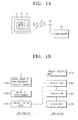
- FIG. 1A is schematic diagram of a structure of a general passive type RF-ID system. As shown therein, the system includes a tag 10 having a coil 30 and an IC 20, an external antenna 40 and a reader 50.
- FIG. 1 B is block diagram explaining the operation of the RF-ID system.
- the coil 30 in the tag 10 receives a magnetic wave radiated by the external antenna 40 (S110).
- the coil 30 generates an inductive current from the magnetic wave according to Faraday's law (S120).
- the IC 20 accesses data stored in an internal memory (not shown) (S130). Such data may include the tag owner's name, member number, resident registration number, whether or not entrance and exit is acceptable, manufacturing date and manufacturer of the tagged product, or any other useful information.
- the coil 30 serves as an internal antenna for the tag 10 and outputs the data in radio frequency signal format (S140).
- the RF-ID reader 50 receives the data through the external antenna 40 (S150) and demodulates the received data (S160). Thus, the tag information can be confirmed (S170).
- Such real-time data can be obtained by measuring the present status of the tagged object or an environment of the tagged object. For example, in the case of barcodes, which are currently most widely used with industrial products, only the basic information on manufacturing number and price of that product is output. However, when storing sensitive goods, such as wine, it is necessary to keep the goods under certain conditions, e.g., within a certain temperature range, in order to efficiently manage the goods.
- the certification system In order to measure a present status, the certification system must include a sensor.
- the tag In case of a RF-ID system, the tag should include a sensor in addition to the coil and the IC. The most logical approach would involve designing the IC to convert the information from the sensor into digital data, so that additional data is output along with the basic data. This can be implemented with recently developed SOC (System On Chip) technology.
- SOC System On Chip
- radio frequency identification (RF-ID) system comprising:
- analog data detected by a sensor can be output by a tag in addition to basic data. This can be achieved while adding only minimal hardware to existing systems.
- the additional data may be provided using a frequency-shifted or amplitude-varied signal.
- the tag portion may include a coil generating an inductive current in response to a magnetic wave from the antenna and serving as an internal antenna for the tag portion to output the composite signal, an integrated circuit driven by the inductive current and retrieving the basic data to be output as a radio frequency signal, the sensor being driven by the inductive current and measuring a present status of an object associated with the tag portion, and a sensor signal generator embedding the additional data measured by the sensor with the radio frequency signal output from the integrated circuit to form the composite signal.
- the tag portion may further include a constant voltage supplying circuit that converts the inductive current generated by the coil into a constant voltage to be supplied to the integrated circuit and the sensor.
- the tag portion may be a sticker, and the coil, the IC and the sensor may be mounted on an adhesive surface of the sticker.
- the RF-ID system may include an input data detection unit for detecting input data in addition to the magnetic wave received from the RF-ID reader to control the integrated circuit to retrieve data in response to the input data, the tag portion and the RF-ID reader performing a two-way wireless certification.
- the sensor signal generator may shift the carrier frequency of the basic data in accordance with the additional data from the sensor.
- the sensor signal generator may include a variable capacitor connected to the coil.
- the variable capacitor may be in parallel with the coil.
- the sensor signal generator may vary the amplitude of the basic data carrier in accordance with the additional data from the sensor.
- the sensor signal generator may include a variable resistor connected to the coil.
- the variable resistor may be in parallel with the coil.
- the invention also provides a method for confirming measured information in a radio frequency identification (RF-ID) system including a tag portion and a RF-ID reader, comprising:
- the method may further include outputting a magnetic wave from the RF-ID reader, inducing a current from the magnetic wave received by the tag portion, and driving the detecting and retrieving using the current.
- the current may be converted into a constant voltage before use.
- the creating of the composite signal may include frequency-shifting a carrier frequency varying an amplitude of a carrier frequency signal carrying the basic data.
- the decoding may include receiving a composite signal of the basic data and the measured data, demodulating the basic data, detecting the measured data, and confirming the basic data and the measured data.
- the detecting of the measured data may include detecting at least one of a frequency shift and an amplitude variation in a carrier frequency carrying the basic data.
- a tag portion for use in a radio frequency identification (RF-ID) system comprising:
- the composite signal output unit may receive the basic data on a carrier frequency and alter the carrier frequency in accordance with the additional data.
- the alteration may include shifting a frequency of the carrier frequency and/or varying an amplitude of the carrier frequency.
- FIG. 2 is a schematic diagram of a configuration of a RF-ID system having a sensor according to the present invention.
- the RF-ID system shown in FIG. 2 includes a tag portion 200 having a coil 230, an IC 210 and a sensor 220.
- An antenna 240 external to the tag portion 200, receives a radio frequency output from the tag portion 200.
- a RF-ID reader 250 processes the basic data and additional data received from the antenna 240.
- FIG. 3 is a block diagram explaining an operation of the RF-ID system according to the present invention.
- a left side of the dashed line indicates an operation of the tag portion 200, and a right side thereof indicates an operation of the RF-ID reader 250.
- a magnetic wave emitted from the RF-ID reader 250 is transmitted to the tag portion 200 (S300).
- the tag portion 200 receives the magnetic wave, the inductive current induced according to Faraday's law flows through the coil 230, thereby supplying the tag portion with power (S310).
- the supplied power allows the IC 210 in the tag portion 200 to access basic data stored in an internal memory (S320).
- the supplied power also allows the sensor 220 to add data measured thereby to the basic data (S330).
- the construction of the sensor 220 is determined depending on a kind of information to be measured. For example, a sensor measuring temperature, humidity, impact, illumination, or any desired characteristic, can be used.
- the additional data and basic data are transmitted through the coil 220 in the tag portion 200 (S340).
- the basic data is transmitted on a carrier frequency of digital data format.
- the additional data from the sensor is transmitted in an analog data format without separate conversion into digital data. This analog format may be embedded with the basic data by frequency-shifting or amplitude-varying the carrier frequency to form a composite signal.
- the RF-ID reader 250 When the composite signal having the additional data and basic data is transmitted by the tag portion 200, the RF-ID reader 250 receives the additional data and basic data through the antenna 240 (S350). Since the basic data carrying basic information necessary for certification is in digital format, the basic data is confirmed by the RF-ID reader 250 through a demodulation process (S360, S370). Since the additional data is in analog format, the RF-ID reader 250 may retrieve this data by detecting a frequency shift or an amplitude variation in the carrier frequency (S380, S390).
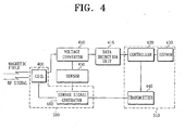
- FIG. 4 is a block diagram of a configuration of a tag portion 200 of the RF-ID system according to the present invention.
- the tag portion includes a signal output unit 500, an IC 510, a voltage converter 410 and a sensor 450.
- the signal output unit 500 includes a coil 400 and a sensor signal generator 460. While the present embodiment illustrates the IC 510 as including a controller 420, an electrically erasable read-only memory (EEPROM) 430, and a transmitter 440, this is only for illustrative purpose, not for limiting the present embodiment.
- EEPROM electrically erasable read-only memory
- the coil 400 acts as an inductive current generator receiving an external magnetic field and serves as an antenna outputting radio frequency signal from the tag portion.
- the voltage-converter 410 converts the inductive current into a constant voltage. Since inductive current is induced depending on the variation of the magnetic field intensity, it is unstable. Thus, it is necessary to convert the inductive current into the constant voltage to drive the IC 510 and the sensor 450.
- the voltage converted by the voltage-converter 410 is supplied to the IC 510 and the sensor 450.
- the RF-ID reader When the above-described embodiment is implemented with a one-way RF-ID system (e.g., in a prepayment system, such as for a bus fare), the RF-ID reader outputs only a simple magnetic wave to drive the tag portion.
- a two-way RF-ID system having a more complicated structure may be used where the RF-ID reader outputs data in addition to the magnetic wave.
- This data is then extracted in the tag portion.
- the data may be extracted by including an optional data detection unit 415 between the voltage-converter 410 and the IC 510.
- the extracted data is input to the controller 420, the controller 420 can retrieve desired information from EEPROM 430 according to the input data, thereby allowing exchange of information between the RF-ID reader 250 and the tag portion 200.
- the controller 420 within the IC 510 When the controller 420 within the IC 510 is supplied with the constant voltage, the basic data stored on EEPROM 430 is retrieved and output to the transmitter 440.
- the transmitter 440 outputs the basic data carried on the carrier frequency in digital data format.
- the voltage from the voltage-converter 410 is supplied to the sensor 450, which detects a desired characteristic and inputs the detected signal to a sensor signal generator 460 in analog data format.
- the sensor 450 may be realized using a simple circuit configuration.
- the sensor signal generator 460 shifts the carrier frequency and/or varies the amplitude of the carrier frequency output from the transmitter 440, thereby outputting additional data detected by the sensor in analog format.
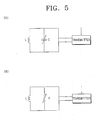
- FIGS. 5A and 5B Configurations of the signal output unit 500 are shown in FIGS. 5A and 5B. Both of these configurations use the coil 400, which is also used as the antenna in the tag portion 200. While the following configurations use specific variable elements in parallel with the coil, other variable elements may be employed and/or the variable element may be provided in series with the coil.
- FIG. 5A is a schematic illustration of the signal output unit 500 including the coil 400 indicated by an inductance L of the coil 400 in parallel with a variable capacitor indicated by a capacitance C of the variable capacitor.
- the capacitance C of the capacitor varies depending on the value measured by the sensor 450, causing the carrier frequency to be shifted.
- FIG. 5B is a schematic illustration of the signal output unit 500 including the coil 400 indicated by an inductance L of the coil 400 in parallel with a variable resistor indicated by a resistance R of the variable resistor.
- the resistance R of the resistor varies depending on the value measured by the sensor 450, causing the amplitude of the carrier frequency to be varied.
- the RF-ID reader 250 extracts the basic data carried on the carrier frequency through the demodulation process and also detects the additional data by measuring the shifted frequency or the varied amplitude.
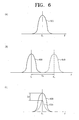
- FIGS. 6A-6C are graphs of basic data and additional data detected by a RF-ID reader according to an embodiment of the present invention.
- FIG. 6A shows a carrier frequency (F c ) signal 600 for the basic data.
- FIG. 6B shows additional data represented by shifting the carrier frequency signal 600 by a certain amount (F d ) to provide a shifted signal 610 at a frequency (F m ) when the signal output unit 500 uses the variable capacitor, as shown in FIG. 5A.
- the RF-ID reader measures the frequency (F m ) of the shifted signal 610 and detects the capacitance of the variable capacitor according to the formula
- F m , resulting in the additional data being detected.
- FIG. 6C shows additional data represented by varying the amplitude of the carrier frequency signal 600 by an amount A d to provide a varied signal 620 when the signal output unit 500 uses the variable resistor as shown in FIG. 5B.
- the RF-ID reader detects the additional data by measuring the variation of the amplitude A d of the varied signal 620 and detects the resistance of the variable resistor. Additionally, both the amplitude may be varied and the frequency may be shifted to embed more than one measured value.
- FIGS. 7A and 7B show further embodiments of the tag portion for the present RF-ID system.
- FIGS. 7A and 7B show tags as an adhesive tape or a sticker, respectively. These tags allow easy removal thereof, as opposed to the card form in a general wireless certification system noted above.
- coils 710 and 750 are mounted on the tag of an adhesive tape 700 or a sticker 740, respectively.
- These tags also include an IC 720 and a sensor 760 driven by current induced by their respective coils.
- the IC 720 and the sensor 760 are driven in a manner that the signal detected by the sensor embedded in the basic data signal by frequency-shifting and/or amplitude-varying the carrier frequency signal output from the transmitter within the IC, as described above.
- the tag portion may be in the form of a sticker or an adhesive tape, allowing simple, disposable use. For example, when a sticker tag is attached to a patient having a condition requiring a status check of a characteristic, such as temperature, any time the RF-ID reader approaches the tag portion, this status information data may be gathered in addition to the basic data such as name, age, and gender of the patient.
Landscapes
- Engineering & Computer Science (AREA)
- Computer Hardware Design (AREA)
- Microelectronics & Electronic Packaging (AREA)
- Physics & Mathematics (AREA)
- General Physics & Mathematics (AREA)
- Theoretical Computer Science (AREA)
- Computer Networks & Wireless Communication (AREA)
- Near-Field Transmission Systems (AREA)
- Radar Systems Or Details Thereof (AREA)
- Burglar Alarm Systems (AREA)
Applications Claiming Priority (2)
| Application Number | Priority Date | Filing Date | Title |
|---|---|---|---|
| KR10-2003-0046143A KR100503475B1 (ko) | 2003-07-08 | 2003-07-08 | 추가 정보 확인이 가능한 rf-id 시스템 및 방법 |
| KR2003046143 | 2003-07-08 |
Publications (2)
| Publication Number | Publication Date |
|---|---|
| EP1496469A1 true EP1496469A1 (de) | 2005-01-12 |
| EP1496469B1 EP1496469B1 (de) | 2006-12-13 |
Family
ID=33448359
Family Applications (1)
| Application Number | Title | Priority Date | Filing Date |
|---|---|---|---|
| EP04252854A Expired - Lifetime EP1496469B1 (de) | 2003-07-08 | 2004-05-17 | RFID-System mit Sensor und Verfahren zum Senden von Zusatzsignalen |
Country Status (6)
| Country | Link |
|---|---|
| US (1) | US7106199B2 (de) |
| EP (1) | EP1496469B1 (de) |
| JP (2) | JP4560341B2 (de) |
| KR (1) | KR100503475B1 (de) |
| AT (1) | ATE348367T1 (de) |
| DE (1) | DE602004003633T2 (de) |
Cited By (3)
| Publication number | Priority date | Publication date | Assignee | Title |
|---|---|---|---|---|
| WO2009102158A3 (ko) * | 2008-02-12 | 2010-05-27 | 한국전자통신연구원 | 무선주파수인식 (rfid) 을 위한 통신방법 |
| WO2011127334A3 (en) * | 2010-04-08 | 2011-12-29 | Access Business Group International Llc | Point of sale inductive systems and methods |
| CN104457822A (zh) * | 2013-09-24 | 2015-03-25 | 财团法人多次元智能It融合系统研究团 | 基于近距离无线通信的传感器测量装置及利用此的测量方法 |
Families Citing this family (12)
| Publication number | Priority date | Publication date | Assignee | Title |
|---|---|---|---|---|
| US20070126561A1 (en) * | 2000-09-08 | 2007-06-07 | Automotive Technologies International, Inc. | Integrated Keyless Entry System and Vehicle Component Monitoring |
| KR100503475B1 (ko) * | 2003-07-08 | 2005-07-25 | 삼성전자주식회사 | 추가 정보 확인이 가능한 rf-id 시스템 및 방법 |
| US7677438B2 (en) * | 2005-06-29 | 2010-03-16 | Microsoft Corporation | Radio frequency certificates of authenticity |
| KR100741353B1 (ko) * | 2005-09-02 | 2007-07-20 | 주식회사 맥스포 | Usn/rfid 태그 통합모듈 |
| US7659851B2 (en) * | 2006-01-11 | 2010-02-09 | Microsoft Corporation | Radio frequency certificates of authenticity and related scanners |
| US7636031B2 (en) * | 2006-05-01 | 2009-12-22 | Honeywell International Inc. | Sensor system including multiple radio frequency identification tags |
| KR100912076B1 (ko) | 2006-07-26 | 2009-08-12 | 한국전자통신연구원 | 리더/태그 통합형 rfid 장치 및 방법 |
| WO2008013418A1 (en) * | 2006-07-26 | 2008-01-31 | Electronics And Telecommunications Research Institute | Apparatus and method for integrated reader and tag |
| US8467278B2 (en) * | 2008-10-06 | 2013-06-18 | Microsoft Corporation | Protecting optical media using random, moving radio frequency scatterers |
| DE102011001169B4 (de) | 2011-03-09 | 2025-06-26 | Maxim Integrated Gmbh | Sicherheitseinrichtung und Verfahren zur Verwendung einer Sicherheitseinrichtung |
| DE102012215006A1 (de) * | 2012-08-23 | 2014-02-27 | Siemens Aktiengesellschaft | Erkennung von Sende-/Empfangsspulen eines Magnetresonanztomographen mit Hilfe von elektronisch lesbaren Etiketten |
| US10586573B2 (en) * | 2018-02-28 | 2020-03-10 | International Business Machines Corporation | Tape data protection by climate label verification |
Citations (5)
| Publication number | Priority date | Publication date | Assignee | Title |
|---|---|---|---|---|
| GB2308947A (en) * | 1996-01-04 | 1997-07-09 | I D Systems Ltd | Identification tag with environmental sensing facility |
| WO2000045331A1 (en) * | 1999-01-29 | 2000-08-03 | International Business Machines Corporation | Method and apparatus for automated measurement of properties of perishable consumer products |
| US6255959B1 (en) * | 1999-08-12 | 2001-07-03 | Micron Technology, Inc. | Electrical apparatuses, methods of forming electrical apparatuses, and termite sensing methods |
| US6297734B1 (en) * | 1999-09-23 | 2001-10-02 | Northrop Grumman Corporation | Randomization of transmit time |
| US20020021216A1 (en) * | 1999-01-21 | 2002-02-21 | Martin Vossiek | Configuration for generating a response signal, carrying an information item, to a received electromagnetic radiation, and method for generating the response signal |
Family Cites Families (10)
| Publication number | Priority date | Publication date | Assignee | Title |
|---|---|---|---|---|
| US6040773A (en) * | 1995-10-11 | 2000-03-21 | Motorola, Inc. | Radio frequency identification tag arranged for magnetically storing tag state information |
| US5736929A (en) * | 1996-06-07 | 1998-04-07 | International Business Machines Corporation | System for concealed serialization utilizing a soft magnetic antitheft element |
| US5973600A (en) * | 1997-09-11 | 1999-10-26 | Precision Dynamics Corporation | Laminated radio frequency identification device |
| EP2259239B1 (de) * | 1998-08-14 | 2012-12-12 | 3M Innovative Properties Company | Anwendungen für Funkfrequenzinformationssysteme |
| JP2000132654A (ja) * | 1998-10-28 | 2000-05-12 | Toshiba Chem Corp | 非接触データキャリアパッケージ |
| US6806808B1 (en) * | 1999-02-26 | 2004-10-19 | Sri International | Wireless event-recording device with identification codes |
| US6294953B1 (en) * | 1999-02-26 | 2001-09-25 | Axcess, Inc. | High sensitivity demodulator for a radio tag and method |
| US6720866B1 (en) | 1999-03-30 | 2004-04-13 | Microchip Technology Incorporated | Radio frequency identification tag device with sensor input |
| JP2001175827A (ja) * | 1999-12-21 | 2001-06-29 | Microhouse:Kk | 共振タグ |
| KR100503475B1 (ko) * | 2003-07-08 | 2005-07-25 | 삼성전자주식회사 | 추가 정보 확인이 가능한 rf-id 시스템 및 방법 |
-
2003
- 2003-07-08 KR KR10-2003-0046143A patent/KR100503475B1/ko not_active Expired - Fee Related
-
2004
- 2004-05-17 DE DE602004003633T patent/DE602004003633T2/de not_active Expired - Lifetime
- 2004-05-17 AT AT04252854T patent/ATE348367T1/de not_active IP Right Cessation
- 2004-05-17 EP EP04252854A patent/EP1496469B1/de not_active Expired - Lifetime
- 2004-05-24 US US10/851,230 patent/US7106199B2/en not_active Expired - Fee Related
- 2004-07-08 JP JP2004201823A patent/JP4560341B2/ja not_active Expired - Fee Related
-
2007
- 2007-02-28 JP JP2007049360A patent/JP4685046B2/ja not_active Expired - Fee Related
Patent Citations (5)
| Publication number | Priority date | Publication date | Assignee | Title |
|---|---|---|---|---|
| GB2308947A (en) * | 1996-01-04 | 1997-07-09 | I D Systems Ltd | Identification tag with environmental sensing facility |
| US20020021216A1 (en) * | 1999-01-21 | 2002-02-21 | Martin Vossiek | Configuration for generating a response signal, carrying an information item, to a received electromagnetic radiation, and method for generating the response signal |
| WO2000045331A1 (en) * | 1999-01-29 | 2000-08-03 | International Business Machines Corporation | Method and apparatus for automated measurement of properties of perishable consumer products |
| US6255959B1 (en) * | 1999-08-12 | 2001-07-03 | Micron Technology, Inc. | Electrical apparatuses, methods of forming electrical apparatuses, and termite sensing methods |
| US6297734B1 (en) * | 1999-09-23 | 2001-10-02 | Northrop Grumman Corporation | Randomization of transmit time |
Cited By (6)
| Publication number | Priority date | Publication date | Assignee | Title |
|---|---|---|---|---|
| WO2009102158A3 (ko) * | 2008-02-12 | 2010-05-27 | 한국전자통신연구원 | 무선주파수인식 (rfid) 을 위한 통신방법 |
| WO2011127334A3 (en) * | 2010-04-08 | 2011-12-29 | Access Business Group International Llc | Point of sale inductive systems and methods |
| GB2492010A (en) * | 2010-04-08 | 2012-12-19 | Access Business Group Int Llc | Point of sale inductive systems and methods |
| CN103109165A (zh) * | 2010-04-08 | 2013-05-15 | 捷通国际有限公司 | 销售点感应系统和方法 |
| CN103109165B (zh) * | 2010-04-08 | 2015-08-19 | 捷通国际有限公司 | 销售点感应系统和方法 |
| CN104457822A (zh) * | 2013-09-24 | 2015-03-25 | 财团法人多次元智能It融合系统研究团 | 基于近距离无线通信的传感器测量装置及利用此的测量方法 |
Also Published As
| Publication number | Publication date |
|---|---|
| US7106199B2 (en) | 2006-09-12 |
| KR100503475B1 (ko) | 2005-07-25 |
| EP1496469B1 (de) | 2006-12-13 |
| KR20050006429A (ko) | 2005-01-17 |
| JP4560341B2 (ja) | 2010-10-13 |
| US20050007250A1 (en) | 2005-01-13 |
| JP2007172654A (ja) | 2007-07-05 |
| DE602004003633T2 (de) | 2007-04-05 |
| DE602004003633D1 (de) | 2007-01-25 |
| JP4685046B2 (ja) | 2011-05-18 |
| ATE348367T1 (de) | 2007-01-15 |
| JP2005032253A (ja) | 2005-02-03 |
Similar Documents
| Publication | Publication Date | Title |
|---|---|---|
| JP4685046B2 (ja) | 追加情報の確認可能なrf−idシステムおよび方法 | |
| US9058552B2 (en) | RFID tag temperature adaptation | |
| EP1084423B1 (de) | Radiofrequenz - identifikationsetikett mit eingang für sensor | |
| JP3526863B2 (ja) | 誘導型読み取り装置の信号伝送およびタグ消費電力測定のための回路 | |
| US7118029B2 (en) | Smart instrument tray RFID reader | |
| US6002343A (en) | Changing Indicia in an electronic tag when tampered with | |
| Want et al. | Ubiquitous electronic tagging | |
| CA2519621A1 (en) | Improved advertising compliance monitoring system | |
| CN101438331A (zh) | 将dac输出与输入信号进行比较以选择性执行一个动作的rf装置 | |
| WO2008016468A2 (en) | System and method for near field data communication with sensors using a radio frequency identification (rfid) protocol | |
| CN102340356A (zh) | 通信系统与通信装置 | |
| Parvathy et al. | RFID based exam hall maintenance system | |
| KR100679208B1 (ko) | 데이터 송수신 시스템과 데이터 송수신 장치 및 방법 | |
| US20070057773A1 (en) | Apparatus and Methods of Universal Radio Frequency Identification Sensing System | |
| CN101737389B (zh) | 一种实现有射频标签功能的钉子 | |
| CN102184627A (zh) | 一种用于恶劣环境的传感器数据采集装置 | |
| Yang et al. | A flexible surface wetness sensor using a RFID technique | |
| KR100795755B1 (ko) | 외부 데이터 및 전원을 유선으로 공급받는 rfid 태그와이를 이용한 측정 데이터 처리 시스템 및 방법 | |
| JP5065385B2 (ja) | トランスポンダおよび前記トランスポンダを有するシステム | |
| JP2007049418A (ja) | マルチインターフェースポート付きバッテリーレス型rfidタグ | |
| Verma et al. | RFID in Libraries: An Overview | |
| JP2005164527A (ja) | 温度検知システム | |
| JATIwAL et al. | A Survey on Radio Frequency Identification (RFId) | |
| TWI415007B (zh) | 感應儲能之無線射頻辨識系統及其執行方法 | |
| Patil | Intelligence Billing System Using Radio Frequency Identification (RFID) and ZIGBEE |
Legal Events
| Date | Code | Title | Description |
|---|---|---|---|
| PUAI | Public reference made under article 153(3) epc to a published international application that has entered the european phase |
Free format text: ORIGINAL CODE: 0009012 |
|
| AK | Designated contracting states |
Kind code of ref document: A1 Designated state(s): AT BE BG CH CY CZ DE DK EE ES FI FR GB GR HU IE IT LI LU MC NL PL PT RO SE SI SK TR |
|
| AX | Request for extension of the european patent |
Extension state: AL HR LT LV MK |
|
| RIN1 | Information on inventor provided before grant (corrected) |
Inventor name: LEE, DONG-HYUN Inventor name: WON, JONG-HWA Inventor name: KU, JA-NAM,132-1201 JUGONG APARTMENT |
|
| 17P | Request for examination filed |
Effective date: 20050223 |
|
| 17Q | First examination report despatched |
Effective date: 20050322 |
|
| AKX | Designation fees paid |
Designated state(s): AT BE BG CH CY CZ DE DK EE ES FI FR GB GR HU IE IT LI LU MC NL PL PT RO SE SI SK TR |
|
| GRAP | Despatch of communication of intention to grant a patent |
Free format text: ORIGINAL CODE: EPIDOSNIGR1 |
|
| GRAS | Grant fee paid |
Free format text: ORIGINAL CODE: EPIDOSNIGR3 |
|
| GRAA | (expected) grant |
Free format text: ORIGINAL CODE: 0009210 |
|
| AK | Designated contracting states |
Kind code of ref document: B1 Designated state(s): AT BE BG CH CY CZ DE DK EE ES FI FR GB GR HU IE IT LI LU MC NL PL PT RO SE SI SK TR |
|
| PG25 | Lapsed in a contracting state [announced via postgrant information from national office to epo] |
Ref country code: SK Free format text: LAPSE BECAUSE OF FAILURE TO SUBMIT A TRANSLATION OF THE DESCRIPTION OR TO PAY THE FEE WITHIN THE PRESCRIBED TIME-LIMIT Effective date: 20061213 Ref country code: FI Free format text: LAPSE BECAUSE OF FAILURE TO SUBMIT A TRANSLATION OF THE DESCRIPTION OR TO PAY THE FEE WITHIN THE PRESCRIBED TIME-LIMIT Effective date: 20061213 Ref country code: IT Free format text: LAPSE BECAUSE OF FAILURE TO SUBMIT A TRANSLATION OF THE DESCRIPTION OR TO PAY THE FEE WITHIN THE PRESCRIBED TIME-LIMIT;WARNING: LAPSES OF ITALIAN PATENTS WITH EFFECTIVE DATE BEFORE 2007 MAY HAVE OCCURRED AT ANY TIME BEFORE 2007. THE CORRECT EFFECTIVE DATE MAY BE DIFFERENT FROM THE ONE RECORDED. Effective date: 20061213 Ref country code: SI Free format text: LAPSE BECAUSE OF FAILURE TO SUBMIT A TRANSLATION OF THE DESCRIPTION OR TO PAY THE FEE WITHIN THE PRESCRIBED TIME-LIMIT Effective date: 20061213 Ref country code: CZ Free format text: LAPSE BECAUSE OF FAILURE TO SUBMIT A TRANSLATION OF THE DESCRIPTION OR TO PAY THE FEE WITHIN THE PRESCRIBED TIME-LIMIT Effective date: 20061213 Ref country code: DK Free format text: LAPSE BECAUSE OF FAILURE TO SUBMIT A TRANSLATION OF THE DESCRIPTION OR TO PAY THE FEE WITHIN THE PRESCRIBED TIME-LIMIT Effective date: 20061213 Ref country code: AT Free format text: LAPSE BECAUSE OF FAILURE TO SUBMIT A TRANSLATION OF THE DESCRIPTION OR TO PAY THE FEE WITHIN THE PRESCRIBED TIME-LIMIT Effective date: 20061213 Ref country code: CH Free format text: LAPSE BECAUSE OF FAILURE TO SUBMIT A TRANSLATION OF THE DESCRIPTION OR TO PAY THE FEE WITHIN THE PRESCRIBED TIME-LIMIT Effective date: 20061213 Ref country code: RO Free format text: LAPSE BECAUSE OF FAILURE TO SUBMIT A TRANSLATION OF THE DESCRIPTION OR TO PAY THE FEE WITHIN THE PRESCRIBED TIME-LIMIT Effective date: 20061213 Ref country code: PL Free format text: LAPSE BECAUSE OF FAILURE TO SUBMIT A TRANSLATION OF THE DESCRIPTION OR TO PAY THE FEE WITHIN THE PRESCRIBED TIME-LIMIT Effective date: 20061213 Ref country code: LI Free format text: LAPSE BECAUSE OF FAILURE TO SUBMIT A TRANSLATION OF THE DESCRIPTION OR TO PAY THE FEE WITHIN THE PRESCRIBED TIME-LIMIT Effective date: 20061213 Ref country code: NL Free format text: LAPSE BECAUSE OF FAILURE TO SUBMIT A TRANSLATION OF THE DESCRIPTION OR TO PAY THE FEE WITHIN THE PRESCRIBED TIME-LIMIT Effective date: 20061213 Ref country code: BE Free format text: LAPSE BECAUSE OF FAILURE TO SUBMIT A TRANSLATION OF THE DESCRIPTION OR TO PAY THE FEE WITHIN THE PRESCRIBED TIME-LIMIT Effective date: 20061213 |
|
| REG | Reference to a national code |
Ref country code: GB Ref legal event code: FG4D |
|
| REG | Reference to a national code |
Ref country code: CH Ref legal event code: EP |
|
| REG | Reference to a national code |
Ref country code: IE Ref legal event code: FG4D |
|
| REF | Corresponds to: |
Ref document number: 602004003633 Country of ref document: DE Date of ref document: 20070125 Kind code of ref document: P |
|
| PG25 | Lapsed in a contracting state [announced via postgrant information from national office to epo] |
Ref country code: BG Free format text: LAPSE BECAUSE OF FAILURE TO SUBMIT A TRANSLATION OF THE DESCRIPTION OR TO PAY THE FEE WITHIN THE PRESCRIBED TIME-LIMIT Effective date: 20070313 Ref country code: SE Free format text: LAPSE BECAUSE OF FAILURE TO SUBMIT A TRANSLATION OF THE DESCRIPTION OR TO PAY THE FEE WITHIN THE PRESCRIBED TIME-LIMIT Effective date: 20070313 |
|
| PG25 | Lapsed in a contracting state [announced via postgrant information from national office to epo] |
Ref country code: ES Free format text: LAPSE BECAUSE OF FAILURE TO SUBMIT A TRANSLATION OF THE DESCRIPTION OR TO PAY THE FEE WITHIN THE PRESCRIBED TIME-LIMIT Effective date: 20070324 |
|
| PG25 | Lapsed in a contracting state [announced via postgrant information from national office to epo] |
Ref country code: PT Free format text: LAPSE BECAUSE OF FAILURE TO SUBMIT A TRANSLATION OF THE DESCRIPTION OR TO PAY THE FEE WITHIN THE PRESCRIBED TIME-LIMIT Effective date: 20070514 |
|
| NLV1 | Nl: lapsed or annulled due to failure to fulfill the requirements of art. 29p and 29m of the patents act | ||
| ET | Fr: translation filed | ||
| REG | Reference to a national code |
Ref country code: CH Ref legal event code: PL |
|
| PLBE | No opposition filed within time limit |
Free format text: ORIGINAL CODE: 0009261 |
|
| STAA | Information on the status of an ep patent application or granted ep patent |
Free format text: STATUS: NO OPPOSITION FILED WITHIN TIME LIMIT |
|
| 26N | No opposition filed |
Effective date: 20070914 |
|
| PG25 | Lapsed in a contracting state [announced via postgrant information from national office to epo] |
Ref country code: MC Free format text: LAPSE BECAUSE OF NON-PAYMENT OF DUE FEES Effective date: 20070531 |
|
| PG25 | Lapsed in a contracting state [announced via postgrant information from national office to epo] |
Ref country code: GR Free format text: LAPSE BECAUSE OF FAILURE TO SUBMIT A TRANSLATION OF THE DESCRIPTION OR TO PAY THE FEE WITHIN THE PRESCRIBED TIME-LIMIT Effective date: 20070314 |
|
| PG25 | Lapsed in a contracting state [announced via postgrant information from national office to epo] |
Ref country code: IE Free format text: LAPSE BECAUSE OF NON-PAYMENT OF DUE FEES Effective date: 20070517 |
|
| PG25 | Lapsed in a contracting state [announced via postgrant information from national office to epo] |
Ref country code: EE Free format text: LAPSE BECAUSE OF FAILURE TO SUBMIT A TRANSLATION OF THE DESCRIPTION OR TO PAY THE FEE WITHIN THE PRESCRIBED TIME-LIMIT Effective date: 20061213 |
|
| PG25 | Lapsed in a contracting state [announced via postgrant information from national office to epo] |
Ref country code: CY Free format text: LAPSE BECAUSE OF FAILURE TO SUBMIT A TRANSLATION OF THE DESCRIPTION OR TO PAY THE FEE WITHIN THE PRESCRIBED TIME-LIMIT Effective date: 20061213 Ref country code: LU Free format text: LAPSE BECAUSE OF NON-PAYMENT OF DUE FEES Effective date: 20070517 |
|
| PG25 | Lapsed in a contracting state [announced via postgrant information from national office to epo] |
Ref country code: TR Free format text: LAPSE BECAUSE OF FAILURE TO SUBMIT A TRANSLATION OF THE DESCRIPTION OR TO PAY THE FEE WITHIN THE PRESCRIBED TIME-LIMIT Effective date: 20061213 Ref country code: HU Free format text: LAPSE BECAUSE OF FAILURE TO SUBMIT A TRANSLATION OF THE DESCRIPTION OR TO PAY THE FEE WITHIN THE PRESCRIBED TIME-LIMIT Effective date: 20070614 |
|
| PGFP | Annual fee paid to national office [announced via postgrant information from national office to epo] |
Ref country code: DE Payment date: 20130423 Year of fee payment: 10 Ref country code: GB Payment date: 20130426 Year of fee payment: 10 |
|
| PGFP | Annual fee paid to national office [announced via postgrant information from national office to epo] |
Ref country code: FR Payment date: 20130515 Year of fee payment: 10 |
|
| REG | Reference to a national code |
Ref country code: DE Ref legal event code: R119 Ref document number: 602004003633 Country of ref document: DE |
|
| GBPC | Gb: european patent ceased through non-payment of renewal fee |
Effective date: 20140517 |
|
| REG | Reference to a national code |
Ref country code: FR Ref legal event code: ST Effective date: 20150130 |
|
| REG | Reference to a national code |
Ref country code: DE Ref legal event code: R119 Ref document number: 602004003633 Country of ref document: DE Effective date: 20141202 |
|
| PG25 | Lapsed in a contracting state [announced via postgrant information from national office to epo] |
Ref country code: DE Free format text: LAPSE BECAUSE OF NON-PAYMENT OF DUE FEES Effective date: 20141202 |
|
| PG25 | Lapsed in a contracting state [announced via postgrant information from national office to epo] |
Ref country code: FR Free format text: LAPSE BECAUSE OF NON-PAYMENT OF DUE FEES Effective date: 20140602 Ref country code: GB Free format text: LAPSE BECAUSE OF NON-PAYMENT OF DUE FEES Effective date: 20140517 |