EP1496520A2 - Enthüllungsverfahren und -vorrichtung bei der Verarbeitung von abgebrannten Kernbrennstoffen - Google Patents
Enthüllungsverfahren und -vorrichtung bei der Verarbeitung von abgebrannten Kernbrennstoffen Download PDFInfo
- Publication number
- EP1496520A2 EP1496520A2 EP04015922A EP04015922A EP1496520A2 EP 1496520 A2 EP1496520 A2 EP 1496520A2 EP 04015922 A EP04015922 A EP 04015922A EP 04015922 A EP04015922 A EP 04015922A EP 1496520 A2 EP1496520 A2 EP 1496520A2
- Authority
- EP
- European Patent Office
- Prior art keywords
- nuclear fuel
- spent nuclear
- fragments
- pins
- decladding
- Prior art date
- Legal status (The legal status is an assumption and is not a legal conclusion. Google has not performed a legal analysis and makes no representation as to the accuracy of the status listed.)
- Granted
Links
Images


Classifications
-
- G—PHYSICS
- G21—NUCLEAR PHYSICS; NUCLEAR ENGINEERING
- G21C—NUCLEAR REACTORS
- G21C19/00—Arrangements for treating, for handling, or for facilitating the handling of, fuel or other materials which are used within the reactor, e.g. within its pressure vessel
- G21C19/34—Apparatus or processes for dismantling nuclear fuel, e.g. before reprocessing ; Apparatus or processes for dismantling strings of spent fuel elements
- G21C19/36—Mechanical means only
- G21C19/365—Removing cannings or casings from fuel
- G21C19/37—Removing cannings or casings from fuel by separating into pieces both the canning or the casing and the fuel element, e.g. by cutting or shearing
-
- Y—GENERAL TAGGING OF NEW TECHNOLOGICAL DEVELOPMENTS; GENERAL TAGGING OF CROSS-SECTIONAL TECHNOLOGIES SPANNING OVER SEVERAL SECTIONS OF THE IPC; TECHNICAL SUBJECTS COVERED BY FORMER USPC CROSS-REFERENCE ART COLLECTIONS [XRACs] AND DIGESTS
- Y02—TECHNOLOGIES OR APPLICATIONS FOR MITIGATION OR ADAPTATION AGAINST CLIMATE CHANGE
- Y02E—REDUCTION OF GREENHOUSE GAS [GHG] EMISSIONS, RELATED TO ENERGY GENERATION, TRANSMISSION OR DISTRIBUTION
- Y02E30/00—Energy generation of nuclear origin
- Y02E30/30—Nuclear fission reactors
-
- Y—GENERAL TAGGING OF NEW TECHNOLOGICAL DEVELOPMENTS; GENERAL TAGGING OF CROSS-SECTIONAL TECHNOLOGIES SPANNING OVER SEVERAL SECTIONS OF THE IPC; TECHNICAL SUBJECTS COVERED BY FORMER USPC CROSS-REFERENCE ART COLLECTIONS [XRACs] AND DIGESTS
- Y02—TECHNOLOGIES OR APPLICATIONS FOR MITIGATION OR ADAPTATION AGAINST CLIMATE CHANGE
- Y02W—CLIMATE CHANGE MITIGATION TECHNOLOGIES RELATED TO WASTEWATER TREATMENT OR WASTE MANAGEMENT
- Y02W30/00—Technologies for solid waste management
- Y02W30/50—Reuse, recycling or recovery technologies
Definitions
- the present invention relates to a decladding method and a decladding device for removing cladding tubes (fuel pins) from the spent nuclear fuel so that fine fragments of the spent nuclear fuel are obtained.
- a fast breeder reactor uses a multiplicity of fuel pins as a nuclear fuel assembly and, therefore, it is necessary to take out the spent nuclear fuel from the fuel pins.
- the shearing In order to shear the nuclear fuel assembly, a large size shearing machine having a hydraulic apparatus is needed. Also, the shearing is of a press-cutting type so that no fine shearing can be done but the shearing of a length size only of 2 to 4 cm can be done. Thus, it is not easy to take out the spent nuclear fuel from the sheared fuel pins.
- the present invention employs a decladding method of spent nuclear fuel characterized in comprising the steps of finely shearing a plurality of spent nuclear fuel pins, made of austenitic stainless steel, in which the spent nuclear fuel is filled into fragments so that a main portion of the fragments is of a size of 1 to 2 mm or less and separating the fragments so obtained into a fuel pin portion and a spent nuclear fuel portion by a magnetic separation.
- the metal fragments of a very small particle size are to be obtained, there is a problem that an abrasion or wear of the shearing device becomes large.
- the metal fragments are changed to have a ferromagnetic nature of a high magnetizing rate.
- the clad of the spent nuclear fuel can be easily removed and the fuel can be efficiently recovered without using a dissolving liquid such as nitric acid.
- the spent nuclear fuel pins are disassembled from the nuclear fuel assembly and the shearing of the spent nuclear fuel pins is carried out with respect to each one pin or each one unit of several pins of the spent nuclear fuel pins by using a rotary type cutter constructed by a plurality of blades and a screen having a plurality of holes.
- a rotary type cutter constructed by a plurality of blades and a screen having a plurality of holes.
- the present invention provides a decladding device of spent nuclear fuel characterized in comprising a shearing device shearing a plurality of spent nuclear fuel pins into fragments and a magnetic separator magnetically separating the fragments obtained by the shearing device, the shearing device comprising a rotary type cutter constructed by a plurality of blades arrayed in parallel with each other and a screen retaining the fragments until the fragments are finely sheared so that a main portion of the fragments is of a size of 1 to 2 mm or less.
- the decladding device of the present invention by using the plurality of blades arrayed in parallel with each other in the rotary type cutter, the spent nuclear fuel pins are finely sheared into fragments and the sheared fragments are retained on the screen so as to be repeatedly sheared so that the main portion of the fragments is of the size of 1 to 2 mm or less.
- the screen has a plurality of holes of a diameter adjusted to meet the mentioned size of the fragments. That is, the fragments sheared to the size of 1 to 2 mm or less pass through the holes of the screen to be discharged.
- the magnetic separator the fragments of the nuclear fuel and those of the fuel pins having the martensitic structure are easily separated from each other. Thereby, the clad of the spent nuclear fuel is efficiently removed and fine fragments of the spent nuclear fuel can be obtained.
- the decladding device of the present invention if the construction is made such that the magnetic separator is arranged below the shearing device, the fragments of the spent nuclear fuel pins finely sheared by the shearing device fall down on the magnetic separator arranged below the shearing device and thereby the fragments can be appropriately supplied to be continuously processed.
- the shearing device is constructed to further comprise a feeder feeding the spent nuclear fuel pins one by one or by a unit of several pins of the spent nuclear fuel pins, then the fuel pins in which the spent nuclear fuel is filled as it is can be supplied so that the fuel pins are sheared in a desired fragment state and separation of the spent nuclear fuel and the fuel pins can be efficiently carried out by the magnetic separation.
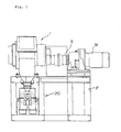
- FIG. 1 showing an entire construction of the decladding device of spent nuclear fuel
- numeral 1 designates a shredder as a shearing device that finely shreds spent nuclear fuel pins, made of austenitic stainless steel, in which the spent nuclear fuel is filled as it is.
- the shredder 1 comprises a rotary type cutter constructed by a plurality of blades and, together with a motor M as a rotational drive unit of the shredder 1, is mounted on a frame F.
- Letter S designates a rotating shaft that transmits a rotational drive force of the motor M to the shredder 1.
- Numeral 20 designates a magnetic separator arranged below the shredder 1.
- the spent nuclear fuel pins are finely shredded by the shredder 1 so that shredded fragments thereof fall down on the magnetic separator 20.
- the magnetic separator 20 receives the shredded fragments and separates them into a fuel pin portion and a spent nuclear fuel portion.
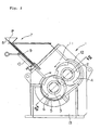
- shredder 1 comprising the rotary type cutter
- two rotating shafts 2, 3 are arranged horizontally in parallel with each other being supported rotatably around respective bearings.
- the rotating shaft 2 has six blades 4 fitted thereto being arranged in the shaft lengthwise direction with a predetermined interval being maintained between each of the blades 4.
- the other rotating shaft 3 has seven blades 5 fitted thereto being arranged in the shaft lengthwise direction with a predetermined interval being maintained between each of the blades 5.
- the blades 4, 5 are assembled together so that they are alternately fitted in between each other so as to be partially lapped one on another and are rotated in the reverse directions to each other as shown by arrows in Fig. 2.
- Numeral 6 designates a screen having a multiplicity of holes of a diameter of several mm bored therein.
- the screen 6 is assembled relative to the blades 5 so that a gap of several mm is formed between the screen 6 itself and a rotational locus of an outer apex end of each of the blades 5.
- Numeral 7 designates a feeder that functions to supply the spent nuclear fuel pins to the blades 4, 5.
- the feeder 7 is constructed comprising a hopper 8 that receives the spent nuclear fuel pins P disassembled from a nuclear fuel assembly, a supply passage 9 and a throwing mechanism 10 of the spent nuclear fuel pins P.
- the blades 4, 5 of the shredder 1 are arranged in a shredding chamber 11.
- the shredding chamber 11 is surrounded by a casing 12 and communicates with a shredded fragment falling port 13 via the screen 6.
- numeral 21 designates a drum that is rotated around a rotating shaft 22.
- a magnet 23 of a semi-circular cross sectional columnar shape is fitted being fixed.
- Numeral 24 designates a shredded fragment throwing port that receives fragments of the spent nuclear fuel pins shredded by the shredder 1.
- Numeral 25 designates a shredded fragment falling chute.
- a vibration feeder 27 having a vibration generator 26 is fitted to the shredded fragment falling chute 25.
- the vibration feeder 27 gives vibration to the shredded fragment falling chute 25 so that the shredded fragments falling down from the shredded fragment throwing port 24 are uniformly dispersed on the shredded fragment falling chute 25 and fall down on the drum 21 in the dispersed state.
- Numeral 28 designates a separating plate that is arranged below the drum 21.
- the separating plate 28 separates a space below the drum 21 into a non-magnetic substance outlet 29 and a magnetic substance outlet 30. That is, after the shredded fragments move along the surface of the drum 21, non-magnetic substances included therein fall down toward the non-magnetic substance outlet 29 drawing a parabolic locus. Further, magnetic substances included in the shredded fragments partly stick to the surface of the drum 21 by the magnetic force of the magnet 23 and, at the position where no magnet 23 exists, leave the surface of the drum 21 to fall down toward the magnetic substance outlet 30. Also, magnetic substances partly draw a locus different from the non-magnetic substances by the influence of the magnetism and fall down toward the magnetic substance outlet 30.
- the decladding device of spent nuclear fuel of the present embodiment is constructed as mentioned above and its decladding function is as follows.
- the spent nuclear fuel pins P of which clads are to be removed are thrown into the hopper 8 and are arrayed in a row on the supply passage 9 to be fed to the throwing mechanism 10.
- the throwing mechanism 10 provided on the supply passage 9 supplies the spent nuclear fuel pins P so that the spent nuclear fuel pins P fall down one by one or in a unit of several pins at a predetermined timing toward the blades 4, 5 of the shredder 1.
- the spent nuclear fuel pins P that have fallen to be so supplied are finely shredded by the blades 4, 5 so that the main part of the shredded fragments is of a size of 1 to 2 mm or less.
- the shredded fragments generated by shredding by meshing portions of the blades 4, 5 pass through the holes of the screen 6 and fall down toward the shredded fragment throwing port 24 of the magnetic separator 20 provided below the shredder 1.
- the shredded fragments larger than the diameter of the holes of the screen 6 are retained on the screen 6 and scraped up by claw tips of the blades 4, 5 to be repeatedly shredded.
- the shredded fragments smaller than the diameter of the holes of the screen 6 fall down on the shredded fragment throwing port 24 and are transferred on the shredded fragment falling chute 25 to fall down on the drum 21.
- the shredded fragment falling chute 25 is vibrated by the vibration feeder 27 comprising the vibration generator 26 so that the shredded fragments transferred on the shredded fragment falling chute 25 are uniformly dispersed and the shredded fragments fall down on the drum 21 in this dispersed state.
- the shredded fragments of the fuel pins made of austenitic stainless steel are given with a magnetic property by the shearing action by the shredder 1. Hence, the shredded fragments of the fuel pins are attracted by the magnetism of the magnet 23 so that they stick to the portion of the drum 21 that is rotating at the position where the magnet 23 is arranged.
- the spent nuclear fuel separated from the fuel pins by the shredding of the spent nuclear fuel pins fall down toward the non-magnetic substance outlet 29 as they are without being influenced by the magnetism of the magnet 23.
- the shredded fragments of the fuel pins while they are being attracted by the magnetism of the magnet 23 to stick to the surface of the drum 21, move together with the rotation of the drum 21 as they are sticking to the surface of the drum 21, but when they come to the position where no magnet 23 is arranged, the influence of the magnet 23 is eliminated and the shredded fragments of the fuel pins leave the surface of the drum 21 and fall down toward the magnetic substance outlet 30.
- the spent nuclear fuel pins are finely shredded by shearing so that there is caused a martensitic phenomenon in the shredded portion of the austenitic stainless steel and thereby the fragments of the fuel pins can be magnetically separated.
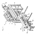
- a second embodiment according to the present invention will be described with reference to Fig. 5.
- parts and components equivalent to those of the decladding device of spent nuclear fuel of the above-mentioned first embodiment are designated with the same reference numerals or letters as shown in Figs. 1 to 4 and repeated description thereon will be omitted.
- numeral 40 designates a shredded fragment conveyor and classifier that has its one end portion (on the right hand side of Fig. 5) constructed to receive the shredded fragments of the spent nuclear fuel pins P that have been shredded by the shredder 1 to fall down from the shredded fragment falling port 13 and to convey them toward the other end portion (on the left hand side of Fig. 5).
- This shredded fragment conveyor and classifier 40 is elastically supported by a plurality (two pieces in Fig. 5) of springs 42.
- Numeral 41 designates an eccentric shaft arrangement that constitutes a vibration generator. By the rotation of this eccentric shaft arrangement 41, the shredded fragment conveyor and classifier 40 is vibrated. In this state, the shredded fragments received in the shredded fragment conveyor and classifier 40 are conveyed as well as classified into a large particle size portion and a small particle size portion.
- the shredded fragments are classified into the large particle size portion and the small particle size portion.
- the shredded fragments of the large particle size are conveyed to a large particle size magnetic separator 50 and the shredded fragments of the small particle size to a small particle size magnetic separator 60.
- numeral 45 designates a nozzle through which off-gas is discharged.
- the reason for the above is that, if the drum speed is increased, the inertia force of the shredded fragments on the surface of the drum becomes larger and thereby the shredded fuel fragments and the shredded metal fragments moving to the non-magnetic substance outlet in front of the drum become more. On the other hand, if the magnetic flux density on the surface of the drum is made higher, while the shredded metal fragments are easily recovered by the influence of the stronger magnetic field, the shredded fuel fragments are also caught therein.
- the magnetic flux density is made higher in the magnetic separation of the shredded fragments of the small particle size, while mixing of the shredded metal fragments into the fuel side is suppressed because of the higher magnetizing rate of the shredded metal fragments and thereby a higher fuel purity can be obtained, the fuel is caught in the metal side and the fuel recovery rate decreases.
- the magnetic flux density is made slightly lower and the drum speed is increased and also, for the shredded fragments of the large particle size, the magnetic flux density is made higher and the drum speed is made slightly lower.
- the shredded fragments are first applied to the classifier and then applied to the magnetic separator, wherein two kinds of the magnetic separators are used, that is, the small particle size magnetic separator 60 providing an effective operation condition for the separation of the shredded fragments of the small particle size and the large particle size magnetic separator 50 providing an effective operation condition for the separation of the shredded fragments of the large particle size.
- the small particle size magnetic separator 60 providing an effective operation condition for the separation of the shredded fragments of the small particle size
- the large particle size magnetic separator 50 providing an effective operation condition for the separation of the shredded fragments of the large particle size.
- the shape or structure of the blades 4, 5 and the number of the blades 4, 5 can be arbitrarily selected.
- the type and structure of the magnetic separator 20 are not limited to the ones as illustrated but various types and structures of the magnetic separator can be employed.
- a magnetic separator of a belt type can be employed other than the rotating drum type.
- the arrangement of the shredder 1 and the magnetic separator 20 is not necessarily limited to the one in which the shredder 1 is arranged above the magnetic separator 20 as in the above-described embodiments.
Landscapes
- Physics & Mathematics (AREA)
- Engineering & Computer Science (AREA)
- Plasma & Fusion (AREA)
- General Engineering & Computer Science (AREA)
- High Energy & Nuclear Physics (AREA)
- Processing Of Solid Wastes (AREA)
Applications Claiming Priority (4)
| Application Number | Priority Date | Filing Date | Title |
|---|---|---|---|
| JP2003194325 | 2003-07-09 | ||
| JP2003194325 | 2003-07-09 | ||
| JP2003285154 | 2003-08-01 | ||
| JP2003285154A JP2005043331A (ja) | 2003-07-09 | 2003-08-01 | 使用済核燃料の脱被覆方法及び脱被覆装置 |
Publications (4)
| Publication Number | Publication Date |
|---|---|
| EP1496520A2 true EP1496520A2 (de) | 2005-01-12 |
| EP1496520A8 EP1496520A8 (de) | 2005-03-30 |
| EP1496520A3 EP1496520A3 (de) | 2008-06-11 |
| EP1496520B1 EP1496520B1 (de) | 2013-09-11 |
Family
ID=33455612
Family Applications (1)
| Application Number | Title | Priority Date | Filing Date |
|---|---|---|---|
| EP20040015922 Expired - Lifetime EP1496520B1 (de) | 2003-07-09 | 2004-07-06 | Enthüllungsverfahren und -vorrichtung bei der Verarbeitung von abgebrannten Kernbrennstoffen |
Country Status (4)
| Country | Link |
|---|---|
| US (1) | US7143969B2 (de) |
| EP (1) | EP1496520B1 (de) |
| JP (1) | JP2005043331A (de) |
| RU (1) | RU2284064C2 (de) |
Cited By (2)
| Publication number | Priority date | Publication date | Assignee | Title |
|---|---|---|---|---|
| CN115881335A (zh) * | 2022-12-14 | 2023-03-31 | 湖南大学 | 高温气冷堆乏燃料包覆颗粒包覆层机械去除装置及其方法 |
| WO2024174372A1 (zh) * | 2023-02-21 | 2024-08-29 | 西安热工研究院有限公司 | 一种高温气冷堆核电燃料装卸系统燃料元件碎片筛分装置 |
Families Citing this family (9)
| Publication number | Priority date | Publication date | Assignee | Title |
|---|---|---|---|---|
| KR100693329B1 (ko) * | 2005-10-26 | 2007-03-09 | 한국원자력연구소 | 사용후 핵연료봉의 분리 수납장치 |
| KR100756396B1 (ko) | 2006-06-29 | 2007-09-10 | 한국원자력연구원 | 조사 핵연료 피복재 탈피장치 |
| US7737218B2 (en) | 2006-12-29 | 2010-06-15 | Bridgestone Corporation | Method for generating free radical capable polymers using tin or silicon halide compounds |
| US8030410B2 (en) * | 2006-12-29 | 2011-10-04 | Bridgestone Corporation | Method for generating free radical capable polymers using carbonyl-containing compounds |
| FR2938110B1 (fr) * | 2008-11-06 | 2013-02-15 | Areva Nc | Procede de vidage de gaines de combustible nucleaire et machine de broyage par deformation de la gaine |
| KR101180857B1 (ko) | 2009-11-17 | 2012-09-07 | 한전원자력연료 주식회사 | 핵연료 집합체의 피복관 절단장치 |
| KR101778580B1 (ko) * | 2016-10-28 | 2017-09-15 | 한국원자력연구원 | 사용후핵연료봉 경사형 절개탈피복장치 |
| CN108295990A (zh) * | 2018-01-25 | 2018-07-20 | 中国原子能科学研究院 | 一种核材料粉碎装置 |
| CN111805481A (zh) * | 2020-07-20 | 2020-10-23 | 中国核动力研究设计院 | 二代核电站乏燃料贮存镉格架解体设备 |
Citations (4)
| Publication number | Priority date | Publication date | Assignee | Title |
|---|---|---|---|---|
| US4248836A (en) | 1977-05-11 | 1981-02-03 | United Kingdom Atomic Energy Authority | Recovery of nuclear fuel material |
| EP0599727A1 (de) | 1992-11-27 | 1994-06-01 | Framatome | Verfahren und Vorrichtung zur Behandlung von aktiven Elementen zur Entsorgung |
| US5452860A (en) | 1993-01-19 | 1995-09-26 | Williams; Robert M. | Material reducing and shredding apparatus |
| JP2002040189A (ja) | 2000-07-28 | 2002-02-06 | Japan Nuclear Cycle Development Inst States Of Projects | 使用済核燃料の前処理方法および前処理装置 |
Family Cites Families (10)
| Publication number | Priority date | Publication date | Assignee | Title |
|---|---|---|---|---|
| US4056052A (en) * | 1976-04-29 | 1977-11-01 | The United States Of America As Represented By The United States Energy Research And Development Administration | Method for shearing spent nuclear fuel assemblies |
| EP0060649B1 (de) * | 1981-03-13 | 1985-10-16 | United Kingdom Atomic Energy Authority | Kernbrennstoffkassette und Verfahren zur Vorbereitung der Kassette für die Herausnahme des Kernbrennstoffmaterials |
| JPH0643288A (ja) * | 1992-01-27 | 1994-02-18 | Mitsubishi Heavy Ind Ltd | 原子燃料のせん断装置 |
| EP0566960A2 (de) * | 1992-04-22 | 1993-10-27 | Siemens Aktiengesellschaft | Zerkleinern und Verpacken von Brennelement-Kästen oder ähnlichen Kernreaktor-Strukturelementen |
| US5299744A (en) * | 1992-08-21 | 1994-04-05 | Garmater Robert A | Granulating, separating and classifying rubber tire materials |
| DE4301066A1 (de) * | 1993-01-16 | 1994-07-21 | Igu Umweltschutzanlagen | Verfahren und Vorrichtung zum Aufbereiten von Kunststoffabfall |
| DE19801286C1 (de) * | 1998-01-15 | 1999-07-22 | Der Gruene Punkt Duales Syst | Verfahren und Aufbereiten von Mischabfällen, Aufbereitungsanlage sowie Puffersilos dafür |
| US5975442A (en) * | 1998-09-02 | 1999-11-02 | Purser; Brian | Cable granulator |
| JP3029620B1 (ja) * | 1999-03-08 | 2000-04-04 | 株式会社 森製作所 | 廃タイヤの粉砕方法及びその装置 |
| JP3612454B2 (ja) * | 1999-10-01 | 2005-01-19 | 松下電器産業株式会社 | 排気循環手段を備えた回転式破砕機及びその制御方法、並びに該破砕機を用いた廃棄物処理装置 |
-
2003
- 2003-08-01 JP JP2003285154A patent/JP2005043331A/ja active Pending
-
2004
- 2004-07-06 EP EP20040015922 patent/EP1496520B1/de not_active Expired - Lifetime
- 2004-07-08 US US10/885,715 patent/US7143969B2/en not_active Expired - Fee Related
- 2004-07-08 RU RU2004121013A patent/RU2284064C2/ru not_active IP Right Cessation
Patent Citations (4)
| Publication number | Priority date | Publication date | Assignee | Title |
|---|---|---|---|---|
| US4248836A (en) | 1977-05-11 | 1981-02-03 | United Kingdom Atomic Energy Authority | Recovery of nuclear fuel material |
| EP0599727A1 (de) | 1992-11-27 | 1994-06-01 | Framatome | Verfahren und Vorrichtung zur Behandlung von aktiven Elementen zur Entsorgung |
| US5452860A (en) | 1993-01-19 | 1995-09-26 | Williams; Robert M. | Material reducing and shredding apparatus |
| JP2002040189A (ja) | 2000-07-28 | 2002-02-06 | Japan Nuclear Cycle Development Inst States Of Projects | 使用済核燃料の前処理方法および前処理装置 |
Cited By (2)
| Publication number | Priority date | Publication date | Assignee | Title |
|---|---|---|---|---|
| CN115881335A (zh) * | 2022-12-14 | 2023-03-31 | 湖南大学 | 高温气冷堆乏燃料包覆颗粒包覆层机械去除装置及其方法 |
| WO2024174372A1 (zh) * | 2023-02-21 | 2024-08-29 | 西安热工研究院有限公司 | 一种高温气冷堆核电燃料装卸系统燃料元件碎片筛分装置 |
Also Published As
| Publication number | Publication date |
|---|---|
| US20050018804A1 (en) | 2005-01-27 |
| RU2004121013A (ru) | 2006-01-10 |
| JP2005043331A (ja) | 2005-02-17 |
| US7143969B2 (en) | 2006-12-05 |
| RU2284064C2 (ru) | 2006-09-20 |
| EP1496520B1 (de) | 2013-09-11 |
| EP1496520A8 (de) | 2005-03-30 |
| EP1496520A3 (de) | 2008-06-11 |
Similar Documents
| Publication | Publication Date | Title |
|---|---|---|
| US7143969B2 (en) | Decladding method and decladding device for spent nuclear fuel reprocessing | |
| JP6780885B2 (ja) | 渦流による夾雑物分離機能を有する比重別廃棄物選別機 | |
| JP6304957B2 (ja) | ショットピーニング装置 | |
| JP2021023862A (ja) | 焼却灰からの貴金属回収方法 | |
| JP4504408B2 (ja) | スプリング含有物処理装置及びスプリング含有物処理方法 | |
| CN100406126C (zh) | 金属罐回收系统 | |
| JP2011156446A (ja) | 石膏ボードの破砕装置 | |
| JP3088954B2 (ja) | 原子炉用燃料ペレットの選別装置 | |
| CN112844691A (zh) | 一种基于计算机控制的金属垃圾分类回收环保装置 | |
| JP4355072B2 (ja) | 通信機器の分別回収方法と装置 | |
| JP2005193095A (ja) | 非鉄金属(特にアルミニウム)とプラスチック(特にポリ塩化ビニル)の選別回収装置及びその方法 | |
| JP2013248567A (ja) | 壁土分離回収装置 | |
| JP2021053564A (ja) | ごみ分別処理方法及び装置 | |
| CN210753225U (zh) | 制备塑木粒子粉料的筛分卸料装置 | |
| JP2021137793A (ja) | 磁力選別装置および磁力選別方法 | |
| JP2000084424A (ja) | 石膏ボード廃材の破砕処理装置 | |
| KR100899791B1 (ko) | 산화철 선별 및 분쇄장치 | |
| JP2000126642A (ja) | シュレッダーダスト処理装置 | |
| KR102943132B1 (ko) | 폐기물 처리 시스템 | |
| DE102021201611A1 (de) | Magnetische Trennvorrichtung und magnetisches Sortierverfahren | |
| JP5892740B2 (ja) | チップ製造装置およびチップの製造方法 | |
| JP2012127717A (ja) | 原子炉における使用済燃料棒の脱被覆方法 | |
| CN110171076B (zh) | 制备塑木粒子粉料的二次筛分装置 | |
| JP7670395B1 (ja) | 廃タイヤ破砕処理装置 | |
| JP2021169064A (ja) | 篩分け装置 |
Legal Events
| Date | Code | Title | Description |
|---|---|---|---|
| PUAI | Public reference made under article 153(3) epc to a published international application that has entered the european phase |
Free format text: ORIGINAL CODE: 0009012 |
|
| 17P | Request for examination filed |
Effective date: 20040706 |
|
| AK | Designated contracting states |
Kind code of ref document: A2 Designated state(s): AT BE BG CH CY CZ DE DK EE ES FI FR GB GR HU IE IT LI LU MC NL PL PT RO SE SI SK TR |
|
| AX | Request for extension of the european patent |
Extension state: AL HR LT LV MK |
|
| RIN1 | Information on inventor provided before grant (corrected) |
Inventor name: KOIZUMI, TSUTOMU C/O TOKAI-WORKS Inventor name: YAMADA, SEIYA C/O TOKAI-WORKS Inventor name: THE OTHER INVENTORS HAVE AGREED TO WAIVE THEIR ENT Inventor name: TAKEUCHI, MASAYUKI C/O TOKAI-WORKS |
|
| RIN1 | Information on inventor provided before grant (corrected) |
Inventor name: TAKEUCHI, MASAYUKI C/O TOKAI-WORKS Inventor name: KOIZUMI, TSUTOMU C/O TOKAI-WORKS Inventor name: SUYAMA, KAZUMASA C/O NAGASAKI SHIPYARD& MACH.W Inventor name: YAMADA, SEIYA C/O TOKAI-WORKS Inventor name: TAKAMI, KAZUO C/O NAGASAKI SHIPYARD& MACH. WOR Inventor name: HARA, TERUO C/O NAGASAKI SHIPYARD & MACH. WORK |
|
| PUAL | Search report despatched |
Free format text: ORIGINAL CODE: 0009013 |
|
| AK | Designated contracting states |
Kind code of ref document: A3 Designated state(s): AT BE BG CH CY CZ DE DK EE ES FI FR GB GR HU IE IT LI LU MC NL PL PT RO SE SI SK TR |
|
| AX | Request for extension of the european patent |
Extension state: AL HR LT LV MK |
|
| AKX | Designation fees paid |
Designated state(s): FR GB |
|
| REG | Reference to a national code |
Ref country code: DE Ref legal event code: 8566 |
|
| 17Q | First examination report despatched |
Effective date: 20110429 |
|
| GRAP | Despatch of communication of intention to grant a patent |
Free format text: ORIGINAL CODE: EPIDOSNIGR1 |
|
| INTG | Intention to grant announced |
Effective date: 20130326 |
|
| RAP1 | Party data changed (applicant data changed or rights of an application transferred) |
Owner name: JAPAN NUCLEAR CYCLE DEVELOPMENT INSTITUTE |
|
| GRAS | Grant fee paid |
Free format text: ORIGINAL CODE: EPIDOSNIGR3 |
|
| GRAA | (expected) grant |
Free format text: ORIGINAL CODE: 0009210 |
|
| AK | Designated contracting states |
Kind code of ref document: B1 Designated state(s): FR GB |
|
| REG | Reference to a national code |
Ref country code: GB Ref legal event code: FG4D |
|
| PLBE | No opposition filed within time limit |
Free format text: ORIGINAL CODE: 0009261 |
|
| STAA | Information on the status of an ep patent application or granted ep patent |
Free format text: STATUS: NO OPPOSITION FILED WITHIN TIME LIMIT |
|
| 26N | No opposition filed |
Effective date: 20140612 |
|
| REG | Reference to a national code |
Ref country code: FR Ref legal event code: PLFP Year of fee payment: 12 |
|
| PGFP | Annual fee paid to national office [announced via postgrant information from national office to epo] |
Ref country code: GB Payment date: 20150724 Year of fee payment: 12 |
|
| PGFP | Annual fee paid to national office [announced via postgrant information from national office to epo] |
Ref country code: FR Payment date: 20150730 Year of fee payment: 12 |
|
| GBPC | Gb: european patent ceased through non-payment of renewal fee |
Effective date: 20160706 |
|
| PG25 | Lapsed in a contracting state [announced via postgrant information from national office to epo] |
Ref country code: FR Free format text: LAPSE BECAUSE OF NON-PAYMENT OF DUE FEES Effective date: 20160801 |
|
| REG | Reference to a national code |
Ref country code: FR Ref legal event code: ST Effective date: 20170331 |
|
| PG25 | Lapsed in a contracting state [announced via postgrant information from national office to epo] |
Ref country code: GB Free format text: LAPSE BECAUSE OF NON-PAYMENT OF DUE FEES Effective date: 20160706 |