EP1496524A2 - Reflektierendes Überspannungsunterdrückendes Kabel. - Google Patents
Reflektierendes Überspannungsunterdrückendes Kabel. Download PDFInfo
- Publication number
- EP1496524A2 EP1496524A2 EP04254122A EP04254122A EP1496524A2 EP 1496524 A2 EP1496524 A2 EP 1496524A2 EP 04254122 A EP04254122 A EP 04254122A EP 04254122 A EP04254122 A EP 04254122A EP 1496524 A2 EP1496524 A2 EP 1496524A2
- Authority
- EP
- European Patent Office
- Prior art keywords
- wire
- auxiliary
- reflective
- surge
- main
- Prior art date
- Legal status (The legal status is an assumption and is not a legal conclusion. Google has not performed a legal analysis and makes no representation as to the accuracy of the status listed.)
- Withdrawn
Links
- 239000004020 conductor Substances 0.000 claims abstract description 32
- 239000012212 insulator Substances 0.000 claims abstract description 22
- 238000010276 construction Methods 0.000 claims abstract description 14
- 238000007747 plating Methods 0.000 claims abstract description 11
- 238000004804 winding Methods 0.000 claims abstract description 5
- 230000009467 reduction Effects 0.000 claims description 8
- 230000006866 deterioration Effects 0.000 description 7
- 230000005540 biological transmission Effects 0.000 description 6
- 230000000694 effects Effects 0.000 description 6
- 238000009413 insulation Methods 0.000 description 3
- 239000000463 material Substances 0.000 description 3
- 230000001629 suppression Effects 0.000 description 3
- BQCIDUSAKPWEOX-UHFFFAOYSA-N 1,1-Difluoroethene Chemical compound FC(F)=C BQCIDUSAKPWEOX-UHFFFAOYSA-N 0.000 description 2
- RYGMFSIKBFXOCR-UHFFFAOYSA-N Copper Chemical compound [Cu] RYGMFSIKBFXOCR-UHFFFAOYSA-N 0.000 description 2
- 238000010586 diagram Methods 0.000 description 2
- 238000001914 filtration Methods 0.000 description 2
- 239000011810 insulating material Substances 0.000 description 2
- 238000000034 method Methods 0.000 description 2
- 230000005855 radiation Effects 0.000 description 2
- 239000002033 PVDF binder Substances 0.000 description 1
- HCHKCACWOHOZIP-UHFFFAOYSA-N Zinc Chemical compound [Zn] HCHKCACWOHOZIP-UHFFFAOYSA-N 0.000 description 1
- 230000009471 action Effects 0.000 description 1
- 230000002411 adverse Effects 0.000 description 1
- 229910052802 copper Inorganic materials 0.000 description 1
- 239000010949 copper Substances 0.000 description 1
- 230000006872 improvement Effects 0.000 description 1
- 238000003780 insertion Methods 0.000 description 1
- 230000037431 insertion Effects 0.000 description 1
- 238000009434 installation Methods 0.000 description 1
- 238000004519 manufacturing process Methods 0.000 description 1
- 238000012986 modification Methods 0.000 description 1
- 230000004048 modification Effects 0.000 description 1
- 230000010355 oscillation Effects 0.000 description 1
- 230000035699 permeability Effects 0.000 description 1
- 229920002981 polyvinylidene fluoride Polymers 0.000 description 1
- 238000011084 recovery Methods 0.000 description 1
- 238000004904 shortening Methods 0.000 description 1
- 239000011701 zinc Substances 0.000 description 1
- 229910052725 zinc Inorganic materials 0.000 description 1
Images




Classifications
-
- H—ELECTRICITY
- H01—ELECTRIC ELEMENTS
- H01B—CABLES; CONDUCTORS; INSULATORS; SELECTION OF MATERIALS FOR THEIR CONDUCTIVE, INSULATING OR DIELECTRIC PROPERTIES
- H01B7/00—Insulated conductors or cables characterised by their form
Definitions
- the present invention is employed in surge suppressing cables of high impedance load systems typified by drive circuits, transmission cables or motors and relates to a reflective surge suppressing cable of excellent economy, ease of use, that offers excellent productivity and practicability and is applicable to a wide range of uses by reducing deterioration of transmission quality and, in addition, reducing the shortening of life that is caused by deterioration of insulation of the cable and connecting equipment thereof and generation of noise due to surges, by suppressing, within the cable itself, surges (unwanted high-voltage waveforms produced by mismatched reflection) generated by impedance mismatching.
- surges can be suppressed by matching the characteristic impedance of the cable with the impedance of the output system and load.
- surges or ringing oscillation generated by for example stray capacitance, residual impedance or reflection, during operation or recovery in a switching circuit
- surges or ringing causes severe deterioration of signal quality.
- Such circumstances cause similar problems not only in the transmission system but also in the drive system as the speed of operation is increased.
- the load is a motor
- manufacturing a matched cable is extremely difficult, since the motor presents impedance (at least 500 ⁇ ) considerable large as compared with the case of an ordinary transmission system.
- the methods that are currently employed involve insertion of a filter using C and L, suppressing the surge level by slowing down the rise time of the output circuit, and employing a cable with a length in a range in which the effect of surge level is small.
- the methods of slowing down the rise time of the output circuit or restricting the length of the cable used do not meet the needs of the market.
- use of filtering requires additional components and, in particular in cases where the load system requires large power, providing the necessary installation space presents a serious problem.
- a problem to be solved by the present invention is to provide a reflective surge suppressing cable wherein the deterioration in the life of the system resulting from for example insulation deterioration of the motor caused by unwanted surges can be suppressed and wherein a reduction of radiation produced by noise generated by surges can be achieved and which is of excellent economy, ease of use, productivity and practicability.
- a reflective surge suppressing cable wherein an auxiliary wire in which shielding is provided on an insulated core wire constituted by applying an insulator onto a conductor is wound in the longitudinal direction around the periphery of a main wire comprising an insulated core wire constituted by applying an insulator onto a conductor, or the auxiliary wire is separated with respect to the main wire by extracting to the outside.
- a reflective surge suppressing cable wherein, in the first embodiment, surges are suppressed by canceling specified frequency components of a surge by reflection, by deliberately generating reflection by adjusting the length of an auxiliary wire when winding the auxiliary wire on in the longitudinal direction or when separating the auxiliary wire by extracting to the outside.
- a reflective surge suppressing cable wherein the conductor of the main wire or auxiliary wire according to the first or second embodiment is covered with an electrically conductive material or plating in order to further promote reduction of high-band noise and increase resistance and/or inductance.
- a reflective surge suppressing cable wherein, in order to further promote reduction of high-band noise, an insulator of high permittivity and/or high dielectric loss is employed as an insulator of the main wire or auxiliary wire according to the first or second embodiment.
- a fifth embodiment of the present invention consists in a construction combining the first, second, third and fourth embodiment. '
- a reflective surge suppressing cable according to the present invention By employing a reflective surge suppressing cable according to the present invention with a high impedance load typified by a motor load, which must be controlled at high speed, unwanted surges can be eliminated and, in addition, a reduction in noise radiation produced by surges can be achieved and a cable obtained which is of excellent economy and ease of use and offers excellent productivity and practicability and excellent space-saving characteristics, and which is applicable to a wide range of uses.
- a first embodiment consists in a reflective surge suppressing cable construction wherein, although not shown in the drawings, an auxiliary wire in which shielding is provided on an insulated core wire constituted by applying an insulator onto a conductor is wound in the longitudinal direction around the periphery of a main wire comprising an insulated core wire constituted by applying an insulator onto a conductor.
- a separated construction may be adopted, in which the auxiliary wire is extracted to the outside with respect to the main wire.
- Copper wire containing for example zinc may be used as a typical example of a conductor.
- PE, PVC or PVDF may be used as typical examples of insulators.
- a construction is adopted in which surges are suppressed by canceling a specified frequency component of a surge by reflection, by deliberately generating reflection by adjusting the length of an auxiliary wire when winding the auxiliary wire on in the longitudinal direction or when separating the auxiliary wire by extracting to the outside.
- a construction is adopted in which the conductors of the main wire and auxiliary wire according to the first or second embodiment are covered with an electrically conductive material or plating in order to further promote reduction of high-band noise and to increase resistance and/or inductance.
- a material of large complex permeability such as Ni plating, of larger conductor resistance than copper, may be used as a typical example of a conductive material or plating material.
- a construction is adopted in which, in order to promote reduction of high-band noise, an insulator of high permittivity and/or high dielectric loss is employed as an insulator of the main wire or auxiliary wire according to the first or second embodiment.
- Vinylidene fluoride may be used as a typical example of an insulator combining high permittivity and high dielectric loss.
- a fifth embodiment consists in a construction combining the first, second, third and fourth embodiments.
- Figure 1A is a cross-sectional view of a typical embodiment of a reflective surge suppressing cable 1 according to the present invention
- Figure 1B is a side view of the reflective surge suppressing cable 1 shown in Figure 1A.
- an auxiliary wire 7 is wound in the axial direction of the main wire 2 about the periphery of the main wire 2.
- the main wire 2 comprises an insulated core wire 3A which is composed of a conductor 4A, an electrically conductive material or plating 5A covering the conductor 4A for increasing the resistance and/or the inductance of the conductor 4A, and a high permittivity insulator and/or high dielectric loss insulator 6A provided on the electrically conductive material or plating 5A.
- the auxiliary wire 7 comprises an insulated core wire 3B which is composed of a conductor 4B, an electrically conductive material or plating 5B covering the conductor 4B for increasing the resistance and/or inductance of the conductor 4B, and a high permittivity insulator and/or high dielectric loss insulator 6B provided on the electrically conductive material or plating 5B.
- a reflective surge suppressing cable can be provided that is capable of high-band use.
- the cable construction according to the present invention can be applied to all ordinary cables, such as single core, double core, coaxial, flat cables and twisted pair cables.
- FIG 2 is a diagram showing the principles of surge suppression using the reflection effect and connection condition of a reflective surge suppressing cable 1 according to the present invention constructed as above.
- the conductors of the main wire and the auxiliary wire are connected. Reflection is deliberately generated by means of this connection condition and a specified frequency, depending on the length (characteristics) of the auxiliary wire, is cancelled by the reflection. Specifically, surges can be suppressed by canceling of frequency components by adjusting the length (characteristics) of the auxiliary wire.
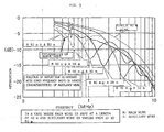
- Figure 3 is a view given in explanation of the relationship between length of the main wire 2 and auxiliary wire 7 and reflection frequency, in respect of a reflective surge suppressing cable 1 according to the present invention.
- This embodiment is an example of the case in which the main wire 2 is always of length 40 m and the auxiliary wire 7 is varied from 10 to 80 m. It can be seen from the Figure that the position of reflection can be matched with the surge frequency based on the length (characteristics) of the auxiliary wire.
- Figure 4 shows the results of a comparison of surge waveforms of a reflective surge suppressing cable according to the present invention and a conventional cable, at a cable length of 10 m.
- FIG. 5 shows the results of comparison of the surge waveforms of a reflective surge suppressing cable according to the present invention and a conventional cable, at a cable length of 40 m.
- the main wire and the auxiliary wire are of the same construction apart from the shielding 8, they need not necessarily be of the same construction and could be somewhat modified.
- the auxiliary wire should be provided with shielding on its outside, an auxiliary wire provided with no shielding may be used.
- the present invention of course may include various modifications.
- the present invention may be applied to surge suppressing cables of high impedance load systems typified by drive circuits, transmission cables and motors; as surges produced by impedance mismatching are suppressed in the cable itself, improvement can be achieved in respect of deterioration of transmission quality and, in addition, amelioration of the adverse effect on life produced by the insulation deterioration of cables and connecting equipment etc. and diminution of noise generation caused by surges can be achieved.
- the present invention offers excellent economy, ease of use, productivity and practicability and has a wide range of application.
Landscapes
- Insulated Conductors (AREA)
- Communication Cables (AREA)
Applications Claiming Priority (2)
| Application Number | Priority Date | Filing Date | Title |
|---|---|---|---|
| JP2003272727A JP4131686B2 (ja) | 2003-07-10 | 2003-07-10 | 反射型サージ抑制ケーブル |
| JP2003272727 | 2003-07-10 |
Publications (2)
| Publication Number | Publication Date |
|---|---|
| EP1496524A2 true EP1496524A2 (de) | 2005-01-12 |
| EP1496524A3 EP1496524A3 (de) | 2006-02-01 |
Family
ID=33448054
Family Applications (1)
| Application Number | Title | Priority Date | Filing Date |
|---|---|---|---|
| EP04254122A Withdrawn EP1496524A3 (de) | 2003-07-10 | 2004-07-09 | Reflektierendes Überspannungsunterdrückendes Kabel. |
Country Status (4)
| Country | Link |
|---|---|
| US (1) | US20050006130A1 (de) |
| EP (1) | EP1496524A3 (de) |
| JP (1) | JP4131686B2 (de) |
| CN (1) | CN1321425C (de) |
Families Citing this family (7)
| Publication number | Priority date | Publication date | Assignee | Title |
|---|---|---|---|---|
| JP4461120B2 (ja) * | 2006-06-26 | 2010-05-12 | 日立オートモティブシステムズ株式会社 | インバータ駆動回転機システム及びそれを用いる電動車両 |
| JP2008204705A (ja) * | 2007-02-19 | 2008-09-04 | Narimasa Saruwatari | 音声信号ケーブル |
| US8471149B2 (en) * | 2010-03-04 | 2013-06-25 | Technical Services For Electronics, Inc. | Shielded electrical cable and method of making the same |
| JP2012105493A (ja) * | 2010-11-12 | 2012-05-31 | Oki Electric Cable Co Ltd | 短尺対応サージ抑制ユニット |
| KR101439893B1 (ko) | 2013-10-16 | 2014-09-12 | 주식회사 한국서지연구소 | 스파이럴 안테나를 이용한 서지 보호 겸용 pci 보호기 |
| WO2016098941A1 (ko) * | 2014-12-18 | 2016-06-23 | 목영일 | 전선속 및 이의 제조방법 |
| JP6110440B2 (ja) * | 2015-07-10 | 2017-04-05 | 894トレーディング株式会社 | 伝送ケーブル及び当該伝送ケーブルを用いた音響ケーブル |
Family Cites Families (13)
| Publication number | Priority date | Publication date | Assignee | Title |
|---|---|---|---|---|
| US1307995A (en) * | 1919-06-24 | Mghtsotg-arresteb | ||
| JPS5229000B2 (de) * | 1974-07-16 | 1977-07-29 | ||
| NL7905279A (nl) * | 1979-07-06 | 1981-01-08 | Philips Nv | Verbindingskabel in digitale systemen. |
| US4719319A (en) * | 1986-03-11 | 1988-01-12 | Amp Incorporated | Spiral configuration ribbon coaxial cable |
| US4687882A (en) * | 1986-04-28 | 1987-08-18 | Stone Gregory C | Surge attenuating cable |
| US5218507A (en) * | 1990-09-06 | 1993-06-08 | Ashley James R | Overhead three-phase power line eliminating fringing electric and magnetic fields |
| US5384429A (en) * | 1993-06-24 | 1995-01-24 | Emerson Electric Co. | Low impedance surge protective device cables for power line usage |
| US5930100A (en) * | 1996-10-31 | 1999-07-27 | Marilyn A. Gasque | Lightning retardant cable |
| JPH10162658A (ja) * | 1996-11-28 | 1998-06-19 | Fujikura Ltd | 金属被架橋ポリエチレン絶縁電力ケーブル |
| US6204445B1 (en) * | 1997-02-06 | 2001-03-20 | Commscope Properties, Llc | Aerially installed communications cable |
| IL121233A0 (en) * | 1997-07-04 | 1998-01-04 | Girit Communication Engineerin | Device for protecting electric and electronic appliances from overvoltages |
| US6414239B1 (en) * | 2000-02-23 | 2002-07-02 | Mag Holdings, Inc. | Method and apparatus for reducing the magnetic field associated with an energized power cable |
| CN2492932Y (zh) * | 2001-06-29 | 2002-05-22 | 方植宁 | 带有抗干扰保护器的电源线 |
-
2003
- 2003-07-10 JP JP2003272727A patent/JP4131686B2/ja not_active Expired - Fee Related
-
2004
- 2004-07-09 EP EP04254122A patent/EP1496524A3/de not_active Withdrawn
- 2004-07-09 US US10/886,697 patent/US20050006130A1/en not_active Abandoned
- 2004-07-09 CN CNB2004100697252A patent/CN1321425C/zh not_active Expired - Lifetime
Also Published As
| Publication number | Publication date |
|---|---|
| JP2005032663A (ja) | 2005-02-03 |
| JP4131686B2 (ja) | 2008-08-13 |
| CN1321425C (zh) | 2007-06-13 |
| US20050006130A1 (en) | 2005-01-13 |
| EP1496524A3 (de) | 2006-02-01 |
| CN1577639A (zh) | 2005-02-09 |
Similar Documents
| Publication | Publication Date | Title |
|---|---|---|
| US6677518B2 (en) | Data transmission cable | |
| US6954346B2 (en) | Filter assembly | |
| US20010042632A1 (en) | Filter for wire and cable | |
| US3824431A (en) | High voltage suppressor for transmission lines | |
| US5510578A (en) | Audio loudspeaker cable assembly | |
| US20140232505A1 (en) | Coil structure and electronic device | |
| US6023201A (en) | Electrical signal transmission device protected against electromagnetic interference | |
| EP1496524A2 (de) | Reflektierendes Überspannungsunterdrückendes Kabel. | |
| JP3835420B2 (ja) | アンテナ装置、及びアンテナ装置の製造方法 | |
| JPH08153545A (ja) | シールドケーブルの接続方法 | |
| JP4093539B2 (ja) | サージ抑制型高速メタリックケーブル | |
| KR20220111548A (ko) | 차량용 이더넷 케이블 | |
| CN1193379C (zh) | 改善了传输特性的同轴电缆 | |
| JPH09199237A (ja) | コネクタ付きシールドケーブル | |
| HUP0000796A2 (en) | Lightning retardant cable | |
| CN112449492B (zh) | 具有高速线材的电路板组件 | |
| JP3938373B2 (ja) | サージ抑制ユニット品 | |
| CN100386951C (zh) | 电动机 | |
| JP2007074811A (ja) | サージ抑制ユニット組み合せ体 | |
| JPH09199238A (ja) | コネクタ付きケーブル | |
| JP4656528B2 (ja) | インダクタンス素子 | |
| JP2009272209A (ja) | ケーブル | |
| JPS63190516A (ja) | 保安器 | |
| JPH0546173B2 (de) | ||
| JPS58186234A (ja) | 誘導対策通信線路 |
Legal Events
| Date | Code | Title | Description |
|---|---|---|---|
| PUAI | Public reference made under article 153(3) epc to a published international application that has entered the european phase |
Free format text: ORIGINAL CODE: 0009012 |
|
| AK | Designated contracting states |
Kind code of ref document: A2 Designated state(s): AT BE BG CH CY CZ DE DK EE ES FI FR GB GR HU IE IT LI LU MC NL PL PT RO SE SI SK TR |
|
| AX | Request for extension of the european patent |
Extension state: AL HR LT LV MK |
|
| PUAL | Search report despatched |
Free format text: ORIGINAL CODE: 0009013 |
|
| AK | Designated contracting states |
Kind code of ref document: A3 Designated state(s): AT BE BG CH CY CZ DE DK EE ES FI FR GB GR HU IE IT LI LU MC NL PL PT RO SE SI SK TR |
|
| AX | Request for extension of the european patent |
Extension state: AL HR LT LV MK |
|
| 17P | Request for examination filed |
Effective date: 20060726 |
|
| AKX | Designation fees paid |
Designated state(s): DE |
|
| 17Q | First examination report despatched |
Effective date: 20100115 |
|
| STAA | Information on the status of an ep patent application or granted ep patent |
Free format text: STATUS: THE APPLICATION IS DEEMED TO BE WITHDRAWN |
|
| 18D | Application deemed to be withdrawn |
Effective date: 20100526 |