EP1496550A2 - Système de montage pour des modules de photovoltaique - Google Patents
Système de montage pour des modules de photovoltaique Download PDFInfo
- Publication number
- EP1496550A2 EP1496550A2 EP04015050A EP04015050A EP1496550A2 EP 1496550 A2 EP1496550 A2 EP 1496550A2 EP 04015050 A EP04015050 A EP 04015050A EP 04015050 A EP04015050 A EP 04015050A EP 1496550 A2 EP1496550 A2 EP 1496550A2
- Authority
- EP
- European Patent Office
- Prior art keywords
- mounting
- frame
- mounting system
- module
- rails
- Prior art date
- Legal status (The legal status is an assumption and is not a legal conclusion. Google has not performed a legal analysis and makes no representation as to the accuracy of the status listed.)
- Withdrawn
Links
Images

Classifications
-
- H—ELECTRICITY
- H02—GENERATION; CONVERSION OR DISTRIBUTION OF ELECTRIC POWER
- H02S—GENERATION OF ELECTRIC POWER BY CONVERSION OF INFRARED RADIATION, VISIBLE LIGHT OR ULTRAVIOLET LIGHT, e.g. USING PHOTOVOLTAIC [PV] MODULES
- H02S20/00—Supporting structures for PV modules
-
- F—MECHANICAL ENGINEERING; LIGHTING; HEATING; WEAPONS; BLASTING
- F24—HEATING; RANGES; VENTILATING
- F24S—SOLAR HEAT COLLECTORS; SOLAR HEAT SYSTEMS
- F24S25/00—Arrangement of stationary mountings or supports for solar heat collector modules
- F24S25/30—Arrangement of stationary mountings or supports for solar heat collector modules using elongate rigid mounting elements extending substantially along the supporting surface, e.g. for covering buildings with solar heat collectors
- F24S25/33—Arrangement of stationary mountings or supports for solar heat collector modules using elongate rigid mounting elements extending substantially along the supporting surface, e.g. for covering buildings with solar heat collectors forming substantially planar assemblies, e.g. of coplanar or stacked profiles
-
- F—MECHANICAL ENGINEERING; LIGHTING; HEATING; WEAPONS; BLASTING
- F24—HEATING; RANGES; VENTILATING
- F24S—SOLAR HEAT COLLECTORS; SOLAR HEAT SYSTEMS
- F24S25/00—Arrangement of stationary mountings or supports for solar heat collector modules
- F24S25/60—Fixation means, e.g. fasteners, specially adapted for supporting solar heat collector modules
- F24S25/63—Fixation means, e.g. fasteners, specially adapted for supporting solar heat collector modules for fixing modules or their peripheral frames to supporting elements
- F24S25/632—Side connectors; Base connectors
-
- F—MECHANICAL ENGINEERING; LIGHTING; HEATING; WEAPONS; BLASTING
- F24—HEATING; RANGES; VENTILATING
- F24S—SOLAR HEAT COLLECTORS; SOLAR HEAT SYSTEMS
- F24S25/00—Arrangement of stationary mountings or supports for solar heat collector modules
- F24S25/60—Fixation means, e.g. fasteners, specially adapted for supporting solar heat collector modules
- F24S25/63—Fixation means, e.g. fasteners, specially adapted for supporting solar heat collector modules for fixing modules or their peripheral frames to supporting elements
- F24S25/634—Clamps; Clips
-
- H—ELECTRICITY
- H02—GENERATION; CONVERSION OR DISTRIBUTION OF ELECTRIC POWER
- H02S—GENERATION OF ELECTRIC POWER BY CONVERSION OF INFRARED RADIATION, VISIBLE LIGHT OR ULTRAVIOLET LIGHT, e.g. USING PHOTOVOLTAIC [PV] MODULES
- H02S30/00—Structural details of PV modules other than those related to light conversion
- H02S30/10—Frame structures
-
- F—MECHANICAL ENGINEERING; LIGHTING; HEATING; WEAPONS; BLASTING
- F24—HEATING; RANGES; VENTILATING
- F24S—SOLAR HEAT COLLECTORS; SOLAR HEAT SYSTEMS
- F24S25/00—Arrangement of stationary mountings or supports for solar heat collector modules
- F24S25/60—Fixation means, e.g. fasteners, specially adapted for supporting solar heat collector modules
- F24S2025/6004—Fixation means, e.g. fasteners, specially adapted for supporting solar heat collector modules by clipping, e.g. by using snap connectors
-
- F—MECHANICAL ENGINEERING; LIGHTING; HEATING; WEAPONS; BLASTING
- F24—HEATING; RANGES; VENTILATING
- F24S—SOLAR HEAT COLLECTORS; SOLAR HEAT SYSTEMS
- F24S25/00—Arrangement of stationary mountings or supports for solar heat collector modules
- F24S2025/80—Special profiles
- F24S2025/801—Special profiles having hollow parts with closed cross-section
-
- F—MECHANICAL ENGINEERING; LIGHTING; HEATING; WEAPONS; BLASTING
- F24—HEATING; RANGES; VENTILATING
- F24S—SOLAR HEAT COLLECTORS; SOLAR HEAT SYSTEMS
- F24S25/00—Arrangement of stationary mountings or supports for solar heat collector modules
- F24S2025/80—Special profiles
- F24S2025/807—Special profiles having undercut grooves
-
- Y—GENERAL TAGGING OF NEW TECHNOLOGICAL DEVELOPMENTS; GENERAL TAGGING OF CROSS-SECTIONAL TECHNOLOGIES SPANNING OVER SEVERAL SECTIONS OF THE IPC; TECHNICAL SUBJECTS COVERED BY FORMER USPC CROSS-REFERENCE ART COLLECTIONS [XRACs] AND DIGESTS
- Y02—TECHNOLOGIES OR APPLICATIONS FOR MITIGATION OR ADAPTATION AGAINST CLIMATE CHANGE
- Y02E—REDUCTION OF GREENHOUSE GAS [GHG] EMISSIONS, RELATED TO ENERGY GENERATION, TRANSMISSION OR DISTRIBUTION
- Y02E10/00—Energy generation through renewable energy sources
- Y02E10/40—Solar thermal energy, e.g. solar towers
- Y02E10/47—Mountings or tracking
-
- Y—GENERAL TAGGING OF NEW TECHNOLOGICAL DEVELOPMENTS; GENERAL TAGGING OF CROSS-SECTIONAL TECHNOLOGIES SPANNING OVER SEVERAL SECTIONS OF THE IPC; TECHNICAL SUBJECTS COVERED BY FORMER USPC CROSS-REFERENCE ART COLLECTIONS [XRACs] AND DIGESTS
- Y02—TECHNOLOGIES OR APPLICATIONS FOR MITIGATION OR ADAPTATION AGAINST CLIMATE CHANGE
- Y02E—REDUCTION OF GREENHOUSE GAS [GHG] EMISSIONS, RELATED TO ENERGY GENERATION, TRANSMISSION OR DISTRIBUTION
- Y02E10/00—Energy generation through renewable energy sources
- Y02E10/50—Photovoltaic [PV] energy
Definitions
- the present invention relates to a mounting system, in particular for fastening of framed photovoltaic modules, with a frame in which a plate-shaped Module element is bordered, wherein the frame at least two Support rails is supported.
- photovoltaic modules bordered by a frame are, the frame is mounted on rails, on a roof or a facade.
- photovoltaic modules usually exist made of multilayer boards, ie photovoltaic elements, a glass pane and a lower cover, and are usually mounted on roofs.
- Such Photovoltaic module is subject to a certain deflection within the frame. Therefore, from a certain size the risk of breakage, especially the Glass pane, relatively large, so for safety reasons a maximum size for the plate-shaped photovoltaic modules may not be exceeded.
- the Size can only be varied by thicker glass panes, which, however the cost of the module element and its weight increase. Especially in countries with colder climatic conditions, such as Austria and Switzerland, the maximum sizes are due to be considered Snow loads only relatively low.
- the module element is within the frame at one or more Places supported. This allows the deflection of the module element limit even with large areas, so that the risk of breakage is minimized. Thereby The size of the module element can be increased and for documenting A roof area requires a relatively small number of frames.
- the module element is supported by a mounting element that on is fixed to the mounting rails.
- a mounting element that on is fixed to the mounting rails.
- the mounting element can be attached in a simple manner to the mounting rail so that the assembly is easy to carry out. For a good support of the mounting element, this preferably extends parallel to the mounting rail and is located on the same.
- mounting element locking elements which with locking means can be connected to the mounting rails.
- the mounting elements only one Section within the module element, for example, only center.
- the mounting elements can also be glued to the module elements, for example be connected with silicone, or with mechanical fasteners. This results in the additional benefit that also acts on the module element Suction forces are absorbed.
- the mounting element by an aluminum extruded profile be formed that can be separated in any length. It can the mounting member also have the same width as the mounting rail, so the visible from below section of the mounting rail is not increased.
- a mounting system 1 comprises a module element 2 in the form of a photovoltaic module, that of several layers, for example with photovoltaic elements, one Glass panel and a lower cover, sandwiched.
- the module element 2 is enclosed in a peripheral frame 3, wherein the frame 3 has a slightly greater height than the module element 2.
- the frame 3 lies on two support rails 4, which are spaced from each other in parallel.
- the mounting rails 4 can be mounted on a roof truss and it can also be more than two mounting rails 4 are used. Furthermore, the mounting rails 4 vertical, be arranged horizontally or inclined.
- the frame 3 rests on the support rails 4 and can be mounted there via known fasteners.
- the module element 2 has a lower height than the height H of the frame 3 and bends without support down through, as shown by the dashed lines. That so sagging modular element 2 'according to the prior art can easily break, the maximum deflection is limited.
- the deflection can be achieved by means of the invention At least reduce mounting elements 5.
- the mounting elements 5 are connected to the Guide rails 4 set and extend at least over part of the length the support rails 4 within the frame 3.
- the module element 2 lies on the Mounting elements 5 and the distance between two support points on Frame or the mounting elements 5 is reduced such that the deflection is almost avoided.
- the mounting elements 5 on the entire length to run within the frame 3 or only selectively set individual points on the mounting rails 4.
- the mounting elements 5 also at an angle to the mounting rails 4, for example between two Mounting rails 4 to be mounted.
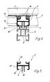
- the support rail 4 is formed of an extruded profile, on which a mounting element 5 as extruded aluminum or Plastic is mounted.
- the mounting rail 6 has an undercut groove 6, on the side inwards protruding ridges 7 are formed. Furthermore, outwardly directed webs are 8 provided on which the frame 3 is supported on the underside. In the groove 6 engage two elastic webs 9 on the mounting member 5, a thickened Have head section 10. The mounting element 5 can thus be on the mounting rail Lock 4 by the thickened head sections 10 in the undercut Groove 6 are inserted by clamping.
- the mounting member 5 also has two laterally folded webs 11, the on the webs 8 of the support rail 4 rest.
- the elastic Seal members 14 may have different heights as needed and are preferably formed as conventional glass plant seals made of EPDM. By the sealing elements 14 different height frame 3 and different thickness module elements 2 are used, since by means of the sealing elements 14 a height compensation can be made.
- the mounting member 5 is shown without sealing elements in detail.
- the Webs 9 project laterally beyond the webs and the folded surface 15 and can thus engage in the groove 6 on the support rail 4.
- an open hollow profile as a mounting element provided that cut off in any length and on a mounting rail 4 can be set. It is also possible other mounting elements, for example closed hollow sections, full profiles or other components to use. Furthermore, it is possible for the attachment of the mounting elements to the Guide rails to use other fasteners. Instead of the strip-shaped contact surfaces By the strip-shaped sealing elements, it is possible round sealing elements to provide for a more punctual edition.
Landscapes
- Engineering & Computer Science (AREA)
- Physics & Mathematics (AREA)
- Life Sciences & Earth Sciences (AREA)
- Sustainable Development (AREA)
- Sustainable Energy (AREA)
- Thermal Sciences (AREA)
- Chemical & Material Sciences (AREA)
- Combustion & Propulsion (AREA)
- Mechanical Engineering (AREA)
- General Engineering & Computer Science (AREA)
- Photovoltaic Devices (AREA)
- Roof Covering Using Slabs Or Stiff Sheets (AREA)
Applications Claiming Priority (2)
| Application Number | Priority Date | Filing Date | Title |
|---|---|---|---|
| DE20310760U DE20310760U1 (de) | 2003-07-11 | 2003-07-11 | Montagesystem |
| DE20310760U | 2003-07-11 |
Publications (2)
| Publication Number | Publication Date |
|---|---|
| EP1496550A2 true EP1496550A2 (fr) | 2005-01-12 |
| EP1496550A3 EP1496550A3 (fr) | 2007-11-14 |
Family
ID=33441932
Family Applications (1)
| Application Number | Title | Priority Date | Filing Date |
|---|---|---|---|
| EP04015050A Withdrawn EP1496550A3 (fr) | 2003-07-11 | 2004-06-26 | Système de montage pour des modules de photovoltaique |
Country Status (2)
| Country | Link |
|---|---|
| EP (1) | EP1496550A3 (fr) |
| DE (1) | DE20310760U1 (fr) |
Cited By (13)
| Publication number | Priority date | Publication date | Assignee | Title |
|---|---|---|---|---|
| WO2007143983A3 (fr) * | 2006-06-15 | 2008-04-03 | Haticon Gmbh | Système de montage, en particulier pour modules solaires |
| EP1947402A1 (fr) * | 2007-01-18 | 2008-07-23 | Aplisun Develop, S.L. | Cadre de support pour panneaux solaires |
| WO2009092401A3 (fr) * | 2008-01-25 | 2010-04-15 | Solarmarkt Ag | Système de fixation de modules solaires |
| WO2010006735A3 (fr) * | 2008-07-14 | 2010-04-22 | Gehrlicher Solar Ag | Structure de fixation destinée à un module solaire de grande surface et module solaire |
| EP2182303A2 (fr) * | 2008-10-22 | 2010-05-05 | Michelberger Energietechnik GmbH | Système de montage |
| ITPD20080379A1 (it) * | 2008-12-22 | 2010-06-23 | Fischer Italia S R L Unipersonal E | Sostegno antiscivolamento per pannelli solari e simili |
| DE202009012001U1 (de) | 2009-09-04 | 2011-02-03 | Mp System Gmbh | Tragkonstruktion für Bauelemente, insbesondere für Photovoltaikpaneele |
| FR2949494A1 (fr) * | 2009-08-25 | 2011-03-04 | Avancis Gmbh & Co Kg | Dispositif de fixation et procede de montage de modules solaires |
| FR2949487A1 (fr) * | 2009-08-26 | 2011-03-04 | Delph | Structure d'integration de panneaux photovoltaiques, profil filant, traverses et pinces pour une telle structure |
| WO2011023777A3 (fr) * | 2009-08-28 | 2011-10-06 | Schüco Tf Gmbh & Co. Kg | Dispositif, système comportant au moins deux dispositifs de ce type et procédé pour équiper une installation photovoltaïque |
| WO2011138344A3 (fr) * | 2010-05-03 | 2013-01-24 | Abakus Solar Ag | Sous-structure pour installation solaire |
| BE1020798A3 (fr) * | 2012-07-20 | 2014-05-06 | Marc Crombez | Ensemble, systeme et procede de fixations de panneaux solaires. |
| CN108377121A (zh) * | 2016-11-25 | 2018-08-07 | 阿特斯阳光电力集团有限公司 | 双玻光伏组件安装支架 |
Families Citing this family (6)
| Publication number | Priority date | Publication date | Assignee | Title |
|---|---|---|---|---|
| RU2281584C1 (ru) * | 2004-12-23 | 2006-08-10 | Общество с ограниченной ответственностью Научно-производственный центр завода "Красное знамя" | Профиль для составного солнечного модуля |
| US8347564B2 (en) | 2007-04-24 | 2013-01-08 | Mitsubishi Electric Corporation | Solar cell module |
| DE102008032985A1 (de) * | 2008-07-14 | 2010-01-21 | Gehrlicher Solar Ag | Befestigungsstruktur für ein großflächiges Solarmodul und Solarmodul |
| DE102009037341A1 (de) * | 2009-08-14 | 2011-02-17 | Ornamin-Kunststoffwerke W. Zschetzsche Gmbh & Co Kg | Aufständerung für Solarkollektoren oder -module |
| DE102015107587A1 (de) * | 2015-05-13 | 2016-12-08 | Hanwha Q Cells Gmbh | Verfahren zur Montage eines gerahmten Solarmoduls |
| US10547270B2 (en) | 2016-02-12 | 2020-01-28 | Solarcity Corporation | Building integrated photovoltaic roofing assemblies and associated systems and methods |
Citations (2)
| Publication number | Priority date | Publication date | Assignee | Title |
|---|---|---|---|---|
| JP2003105940A (ja) | 2001-09-28 | 2003-04-09 | Sekisui Chem Co Ltd | 太陽電池モジュールの設置構造 |
| WO2003045764A1 (fr) * | 2001-11-14 | 2003-06-05 | Enno Roggemann Gmbh & Co. Kg | Module de plancher conçu pour un vehicule |
Family Cites Families (7)
| Publication number | Priority date | Publication date | Assignee | Title |
|---|---|---|---|---|
| US4611090A (en) * | 1984-12-28 | 1986-09-09 | Standard Oil Company | Semirigid photovoltaic module assembly and structural support therefor |
| DE29503314U1 (de) * | 1995-02-14 | 1995-04-27 | Energiebiss Gesellschaft für Sonnenenergienutzung mbH Berlin, 10777 Berlin | Befestigungsvorrichtung zur definierten Positionierung von Solarmodulen auf Schrägdächern |
| JPH1054118A (ja) * | 1996-08-08 | 1998-02-24 | Canon Inc | 太陽電池モジュール |
| US6201179B1 (en) * | 1997-10-03 | 2001-03-13 | Nick Dalacu | Array of photovoltaic modules for an integrated solar power collector system |
| US6365824B1 (en) * | 1999-07-21 | 2002-04-02 | Kaneka Corporation | Roof tile-cum-solar battery module |
| DE20110896U1 (de) * | 2001-07-04 | 2001-10-18 | Heisterkamp, Andrea, 46354 Südlohn | Auflageleiste für Fassadenelemente und Anordnung von Fassadenelementen |
| DE20119629U1 (de) * | 2001-11-27 | 2002-03-07 | Abs Gmbh Storkow | Ständer, insbesondere Dachaufständer für Photovoltaik- und thermische Module |
-
2003
- 2003-07-11 DE DE20310760U patent/DE20310760U1/de not_active Expired - Lifetime
-
2004
- 2004-06-26 EP EP04015050A patent/EP1496550A3/fr not_active Withdrawn
Patent Citations (2)
| Publication number | Priority date | Publication date | Assignee | Title |
|---|---|---|---|---|
| JP2003105940A (ja) | 2001-09-28 | 2003-04-09 | Sekisui Chem Co Ltd | 太陽電池モジュールの設置構造 |
| WO2003045764A1 (fr) * | 2001-11-14 | 2003-06-05 | Enno Roggemann Gmbh & Co. Kg | Module de plancher conçu pour un vehicule |
Cited By (18)
| Publication number | Priority date | Publication date | Assignee | Title |
|---|---|---|---|---|
| JP2009540161A (ja) * | 2006-06-15 | 2009-11-19 | ハティコン ゲゼルシャフト ミット ベシュレンクター ハフトゥンク | 特に太陽光モジュール用の据え付けシステム |
| US8936224B2 (en) | 2006-06-15 | 2015-01-20 | Sapa Holding Gmbh | Mounting system, especially for solar modules |
| WO2007143983A3 (fr) * | 2006-06-15 | 2008-04-03 | Haticon Gmbh | Système de montage, en particulier pour modules solaires |
| EP1947402A1 (fr) * | 2007-01-18 | 2008-07-23 | Aplisun Develop, S.L. | Cadre de support pour panneaux solaires |
| WO2009092401A3 (fr) * | 2008-01-25 | 2010-04-15 | Solarmarkt Ag | Système de fixation de modules solaires |
| CN102119305B (zh) * | 2008-07-14 | 2014-05-28 | 格尔丽舍太阳能有限公司 | 用于大型太阳能模组的固定结构和太阳能模组 |
| WO2010006735A3 (fr) * | 2008-07-14 | 2010-04-22 | Gehrlicher Solar Ag | Structure de fixation destinée à un module solaire de grande surface et module solaire |
| EP2182303A2 (fr) * | 2008-10-22 | 2010-05-05 | Michelberger Energietechnik GmbH | Système de montage |
| ITPD20080379A1 (it) * | 2008-12-22 | 2010-06-23 | Fischer Italia S R L Unipersonal E | Sostegno antiscivolamento per pannelli solari e simili |
| FR2949494A1 (fr) * | 2009-08-25 | 2011-03-04 | Avancis Gmbh & Co Kg | Dispositif de fixation et procede de montage de modules solaires |
| WO2011023902A3 (fr) * | 2009-08-25 | 2011-12-22 | Saint-Gobain Glass France | Dispositif de fixation et procede de montage de modules solaires |
| US8887454B2 (en) | 2009-08-25 | 2014-11-18 | Saint-Gobain Glass France | Solar module attachment device and mounting method |
| FR2949487A1 (fr) * | 2009-08-26 | 2011-03-04 | Delph | Structure d'integration de panneaux photovoltaiques, profil filant, traverses et pinces pour une telle structure |
| WO2011023777A3 (fr) * | 2009-08-28 | 2011-10-06 | Schüco Tf Gmbh & Co. Kg | Dispositif, système comportant au moins deux dispositifs de ce type et procédé pour équiper une installation photovoltaïque |
| DE202009012001U1 (de) | 2009-09-04 | 2011-02-03 | Mp System Gmbh | Tragkonstruktion für Bauelemente, insbesondere für Photovoltaikpaneele |
| WO2011138344A3 (fr) * | 2010-05-03 | 2013-01-24 | Abakus Solar Ag | Sous-structure pour installation solaire |
| BE1020798A3 (fr) * | 2012-07-20 | 2014-05-06 | Marc Crombez | Ensemble, systeme et procede de fixations de panneaux solaires. |
| CN108377121A (zh) * | 2016-11-25 | 2018-08-07 | 阿特斯阳光电力集团有限公司 | 双玻光伏组件安装支架 |
Also Published As
| Publication number | Publication date |
|---|---|
| EP1496550A3 (fr) | 2007-11-14 |
| DE20310760U1 (de) | 2004-11-18 |
Similar Documents
| Publication | Publication Date | Title |
|---|---|---|
| EP1496550A2 (fr) | Système de montage pour des modules de photovoltaique | |
| DE102007027997B4 (de) | Befestigungseinrichtung für an einem Gestellaufbau anzuordnende flächige rahmenlose Bauteile, insbesondere Solarmodule | |
| EP2238393B1 (fr) | Système de fixation de modules solaires | |
| DE102004055187B4 (de) | Profilleistenpaar für Photovoltaik-Module | |
| DE19632493A1 (de) | Befestigungselement zum Befestigen eines flachen plattenförmigen Körpers auf einer Unterlage | |
| EP2304124B1 (fr) | Structure de toit | |
| DE202014006016U1 (de) | Montageklammer | |
| DE102014011022A1 (de) | Montageklammer | |
| DE3423227A1 (de) | Haltevorrichtung mit halterung fuer sonnenkollektoren | |
| EP2666948A1 (fr) | Agencement de cadre pour un panneau de porte sectionnelle | |
| DE102014011364B4 (de) | Befestigungssystem zur Befestigung von plattenförmigen Fassadenelementen | |
| DE202010017422U1 (de) | Solarmodulanordnung | |
| DE202018106077U1 (de) | Glasträgerkonstruktion und Rahmenkonstruktion | |
| DE102021101997A1 (de) | Leistenanordnung zum Füllen eines Spaltbereichs | |
| DE102017011043A1 (de) | Befestigungsvorrichtung für eine komfortable Befestigung von Leichtbau-Platten als Dach- und Fassadenplattensystemen sowie Leichtbau-Platte in Sandwichbauweise mit Befestigungsvorrichtung | |
| EP3591158B1 (fr) | Composant pour construction | |
| DE2806025A1 (de) | Fenster- oder tuerrahmen | |
| DE9104769U1 (de) | Haltevorrichtung | |
| DE102012102243A1 (de) | Rahmenbausatz, Solarmodulvorrichtung und Solarmodul-Montageverfahren | |
| DE19520419A1 (de) | Befestigungsvorrichtung für Balkonverkleidungselemente | |
| DE102020101708A1 (de) | Befestigungsvorrichtung und Fassade | |
| DE102021115302A1 (de) | PV-Modulfassadenkonstruktion zur Integration in bestehende Fassadenoberfläche | |
| DE9305802U1 (de) | Konsole zur Halterung von flächigen Bauteilen, insbesondere Glasscheiben | |
| DE102017100617B4 (de) | Pfosten-Riegel-Konstruktion | |
| EP2896909B1 (fr) | Système de montage en toiture de modules solaires |
Legal Events
| Date | Code | Title | Description |
|---|---|---|---|
| PUAI | Public reference made under article 153(3) epc to a published international application that has entered the european phase |
Free format text: ORIGINAL CODE: 0009012 |
|
| AK | Designated contracting states |
Kind code of ref document: A2 Designated state(s): AT BE BG CH CY CZ DE DK EE ES FI FR GB GR HU IE IT LI LU MC NL PL PT RO SE SI SK TR |
|
| AX | Request for extension of the european patent |
Extension state: AL HR LT LV MK |
|
| PUAL | Search report despatched |
Free format text: ORIGINAL CODE: 0009013 |
|
| AK | Designated contracting states |
Kind code of ref document: A3 Designated state(s): AT BE BG CH CY CZ DE DK EE ES FI FR GB GR HU IE IT LI LU MC NL PL PT RO SE SI SK TR |
|
| AX | Request for extension of the european patent |
Extension state: AL HR LT LV MK |
|
| 17P | Request for examination filed |
Effective date: 20080425 |
|
| AKX | Designation fees paid |
Designated state(s): AT BE BG CH CY CZ DE DK EE ES FI FR GB GR HU IE IT LI LU MC NL PL PT RO SE SI SK TR |
|
| 17Q | First examination report despatched |
Effective date: 20080718 |
|
| STAA | Information on the status of an ep patent application or granted ep patent |
Free format text: STATUS: THE APPLICATION IS DEEMED TO BE WITHDRAWN |
|
| 18D | Application deemed to be withdrawn |
Effective date: 20140103 |