EP1496600B1 - Linearantrieb - Google Patents
Linearantrieb Download PDFInfo
- Publication number
- EP1496600B1 EP1496600B1 EP04015931A EP04015931A EP1496600B1 EP 1496600 B1 EP1496600 B1 EP 1496600B1 EP 04015931 A EP04015931 A EP 04015931A EP 04015931 A EP04015931 A EP 04015931A EP 1496600 B1 EP1496600 B1 EP 1496600B1
- Authority
- EP
- European Patent Office
- Prior art keywords
- rotor
- bearing
- linear drive
- linear
- drive system
- Prior art date
- Legal status (The legal status is an assumption and is not a legal conclusion. Google has not performed a legal analysis and makes no representation as to the accuracy of the status listed.)
- Expired - Lifetime
Links
- 230000033001 locomotion Effects 0.000 claims description 19
- 230000008878 coupling Effects 0.000 claims description 18
- 238000010168 coupling process Methods 0.000 claims description 18
- 238000005859 coupling reaction Methods 0.000 claims description 18
- 238000000034 method Methods 0.000 claims 1
- 238000005096 rolling process Methods 0.000 description 6
- 230000008901 benefit Effects 0.000 description 5
- 238000005516 engineering process Methods 0.000 description 5
- 238000004519 manufacturing process Methods 0.000 description 4
- 230000005540 biological transmission Effects 0.000 description 2
- 239000000463 material Substances 0.000 description 2
- 239000002184 metal Substances 0.000 description 2
- 230000009467 reduction Effects 0.000 description 2
- XLYOFNOQVPJJNP-UHFFFAOYSA-N water Substances O XLYOFNOQVPJJNP-UHFFFAOYSA-N 0.000 description 2
- 238000003466 welding Methods 0.000 description 2
- 229910001369 Brass Inorganic materials 0.000 description 1
- 229910000906 Bronze Inorganic materials 0.000 description 1
- 238000005299 abrasion Methods 0.000 description 1
- 230000009471 action Effects 0.000 description 1
- 230000006978 adaptation Effects 0.000 description 1
- 230000004323 axial length Effects 0.000 description 1
- 239000010951 brass Substances 0.000 description 1
- 239000010974 bronze Substances 0.000 description 1
- 230000008859 change Effects 0.000 description 1
- 238000006243 chemical reaction Methods 0.000 description 1
- KUNSUQLRTQLHQQ-UHFFFAOYSA-N copper tin Chemical compound [Cu].[Sn] KUNSUQLRTQLHQQ-UHFFFAOYSA-N 0.000 description 1
- 238000009795 derivation Methods 0.000 description 1
- 238000009826 distribution Methods 0.000 description 1
- 238000004806 packaging method and process Methods 0.000 description 1
- 230000000149 penetrating effect Effects 0.000 description 1
- 239000004033 plastic Substances 0.000 description 1
- 238000000926 separation method Methods 0.000 description 1
- 239000004575 stone Substances 0.000 description 1
- 238000003860 storage Methods 0.000 description 1
Images

Classifications
-
- H—ELECTRICITY
- H02—GENERATION; CONVERSION OR DISTRIBUTION OF ELECTRIC POWER
- H02K—DYNAMO-ELECTRIC MACHINES
- H02K7/00—Arrangements for handling mechanical energy structurally associated with dynamo-electric machines, e.g. structural association with mechanical driving motors or auxiliary dynamo-electric machines
- H02K7/06—Means for converting reciprocating motion into rotary motion or vice versa
Definitions
- the invention relates to a linear drive for adjusting operations for generating translational feed movements.
- Linear motors and linear spindle motors are known as linear drives from the prior art. While in a linear motor in operation a traveling field between the current-carrying primary part and the reaction part is formed in the linear spindle motor, however, a rotating field is generated that is used to convert a rotational movement of the rotor in a translational movement of the threaded spindle.
- Linear spindle motors have a current-carrying stator and a rotating rotor in which a rotating field is induced. On or in the rotor, a threaded nut is arranged, which drives a suitable screw or threaded spindle during rotation of the rotor. The axial feed movement of the spindle is used to perform an actuating movement of an actuator.
- Such linear spindle motors are used in practice in the field of laboratory and medical technology, sorting technology, the food industry, in machine tool manufacturing, in home and building technology, the packaging industry and in the automotive sector and consumer electronics.
- the drive unit consists of energizable coils and a rotor which is designed as a hollow shaft.
- the rotor is mounted twice using radial bearings.
- the rotor is coupled by means of connecting elements with a spindle.
- an adjusting rod is provided with internal thread, which slides axially on the spindle.
- the axial and outboard end of the control rod can be coupled with a functional element for welding.
- the control rod is fully equipped over its longitudinal extent with the already mentioned internal thread.
- unspecified bearing plate is arranged, which is penetrated by an axial end of the spindle. At this axial end of the spindle, a screw is arranged to operate the spindle and thus also the spindle completely enclosing the control rod, if necessary, manually.
- linear spindle motors have a large design length due to the design and cause a considerable noise emission.
- the reason for this is to call the bearing of the rotor by means of a rolling bearing and designed as a plain bearing emergency camp.
- the rolling bearing generates a tilting moment, which means that the rotor is no longer guided parallel to the stator. Tipping may cause the rotor to rub against the stator.
- the object of the invention is to develop a linear actuator for actuating operations, which is cheaper to manufacture at the same functional size, which is formed more compact and has a higher smoothness.
- the rotor which has an axially disposed and an external thread having rotor shaft, bell-shaped with an open end and a closed end face is formed, and at least partially enclosing the rotor shaft and led out to the open end of the rotor control rod is provided for the linear movement, whose rotor located in the first end has a passable, seated on the rotor shaft with external thread threaded nut.
- the bearing of the rotor shaft is effected by at its axial ends beyond both end faces of the bell-shaped rotor also reaching sliding journals, which are each guided in a sliding bearing and which are placed on or inside the end shields.
- the bell-shaped rotor extends frontally between the end shields of the housing, wherein the open end side of the rotor in the direction of the drive bearing plate and the closed end face of the rotor in the direction of the Nodrive bearing plate has.
- the rotor shaft protruding at least on the open end side of the rotor, which is provided with an external thread, arranged axially, wherein the protruding from the open end of the rotor and the rotor shaft at least partially enclosing the adjusting rod with its threaded nut fitted passably.
- the fork-shaped or hollow cylinder segment-shaped adjusting rod which at least partially encloses the rotor shaft in its longitudinal extension, has a first end, which is designed as a threaded nut and is in axial operative connection with the rotor shaft.
- the adjoining region of the control rod has the form of hollow cylinder segments, the ends of which also extend in the retracted position of the control rod beyond the region of the drive end shield.
- the first end and the second end of the control rod are non-positively and / or positively connected by at least one fork leg or by hollow cylinder segments.
- the fork legs are formed in pairs and arranged diametrically for reasons of uniform power distribution and transmission.
- the fork leg (s) penetrate the drive end shield, so that a linear movement in the direction of the drive end shield can be realized.
- the cross-section of the fork leg or the hollow cylinder segments of the control rod of the cross-sectional shape of a breakthrough in the drive bearing plate is adjusted so that the control rod is torsion and positively guided with a clearance fit in the opening of the drive bearing plate and supported.
- the breakthrough of the drive end shield is therefore designed as anti-rotation and linear guide to prevent tilting of the control rod (threaded nut).
- the rotor shaft attached to the rotor shaft is mounted in contrast to conventional rotors by means of two identically designed plain bearings, which brings several advantages. On the one hand can be dispensed with a costly rolling bearings and on the other hand, the rotor tends during rotation to no tilting play.
- the rotor shaft has only one thanks to the stable bearing Degree of freedom.
- the axial ends of the rotor shaft are designed as plain bearing journals that extend beyond the end faces of the bell-shaped rotor.
- Another not to be underestimated advantage of this plain bearing is that the air gap between the stator and the rotor in the direction of the longitudinal extension of the rotor of the linear drive is constant. The air gap is between 0.1 mm and 0.4 mm.
- the plain bearings are designed as combined transverse and longitudinal bearings and can thus absorb radial and axial forces.
- the radial force application of the rotor shaft is counteracted by means of two bearing shells or a bearing bush in which the lateral surfaces of the end regions of the rotor shaft slide. These end regions are preferably designed as plain bearing journals.
- thrust bearings are used for the derivation of the axial forces u.a. are generated by the axial movement play of the rotor shaft.
- These axial bearings preferably have bearing plates, for example of stone or metal, which surround and contact the end faces of the plain bearing journal of the rotor shaft. These bearing plates are each formed with a flat and a spherical surface.
- a ball is used instead of a track plate. Due to their shape, balls are particularly well suited for reducing the Hertzian pressure which occurs during rotation, which occurs between the plain bearing journal and the sliding bearing. In addition, commercially available metal balls can be used, which are much cheaper to manufacture than bearing plates.
- the plain bearings can be made of all common bearing materials, such. B. sintered bronze, plastic or brass. In order to avoid abrasion on the plain bearing journal of the rotor shaft at high load cycle and to achieve good coefficients of friction, these are preferably made of a harder material such as the plain bearings.
- the linear actuating movement of the control rod is transmitted via a coupling point to an application-specific functional element.
- the coupling point is preferably arranged outside the housing for reasons of interchangeability.
- the actuating rod thus extends from the housing interior to the coupling point, during which the functional element extends from the coupling point to an actuator.
- the coupling point may be formed as a separate component or formed on the control rod. It has proved to be particularly advantageous with respect to the axial force transmission when the adjusting rod is brought into engagement with the functional element by means of bayonet or snap connections or comparable form-locking connecting elements.
- brackets are used which transmit high tensile and shear forces.
- a particular advantage of the linear drive according to the invention is that the formed with a threaded nut first end of the control rod is guided axially movable only within the bell-shaped rotor, which contributes to a significant reduction in length of the linear drive.
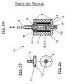
- the Fig. 1 a shows a schematic representation of a linear spindle motor 14 of the prior art in cross section.
- the linear spindle motor 14 includes the stator 10, the housing 11, the front side of the housing 11 comprehensive bearing plates 5, the rotor 2 with attached nut 4.3, the threaded spindle 15 and the control rod 4.
- the threaded spindle 15 has an external thread 3.1, the maximum to extends to the drive end shield 5.1.
- the threaded spindle 15 is positively and / or positively connected to an actuating rod 4 in axial operative connection.
- the control rod 4 is formed directly in the region of the drive bearing plate 5.1 as a square and is secured by one of the cross section of this square corresponding implementation by twisting.
- control rod 4 is formed in the area outside the anti-rotation 8 as a rod or rod with a smooth surface, wherein the outside of the housing 11 located axial end of the control rod 4 is formed simultaneously as a non-illustrated functional element 13.
- the bearing of the cylindrical rotor 2 takes place indirectly via the control rod 4 and the threaded spindle 15th
- the threaded spindle 15 is supported by means of an emergency bearing 17 and standing with this threaded spindle 15 in axial operative connection actuating rod 4 by means of a rolling bearing.
- the roller bearing 16 is usually arranged in the region of the drive bearing plate 5.1, during which the emergency bearing 17 designed as a sliding bearing is arranged in the region of the Nodrive bearing plate 5.2.
- the emergency bearing 17 is designed to ensure the axial play of movement of the threaded spindle 15 in each operating condition. As operating state, each position of the threaded spindle 15 should be understood, which it can assume during its linear movement. As in Fig. 2b can be seen, the Nodrive bearing plate 5.2 is stepped concentric and thus has no flat outer surface.
- the axial length of the linear spindle motor 14 is determined by the maximum possible travel of the threaded spindle 15 and control rod 4.
- the Fig. 1b and 1c illustrate a schematic representation of the drive bearing plate 5.1 of a linear spindle motor 14 of the prior art in the axial and cross section.
- the drive bearing plate 5.1 has a central opening in the form of a circular bore.
- the diameter of the bore corresponds to the outer diameter of a threaded spindle 15, which is guided axially through the bore.
- the bore may have an annular seal.
- the outside of the drive bearing plate 5.1 arranged anti-rotation 8 is only indicated by a coaxial circle.
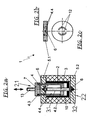
- the Fig. 2a shows a schematic representation of the linear drive 1 according to the invention in cross section. It is particularly noticeable that the threaded nut is not connected to the rotor 2 as in conventional linear spindle motors 14 and is therefore subject to relative movement relative to the stator 10, but is fastened to one end of the fork-shaped or hollow cylinder segment-shaped axially movable control rod 4 within the linear drive 1, and thus facing an absolute movement the stator 10 is subjected.
- a first end 4.2 of the control rod 4, which is arranged within the rotor 2, is cylindrical in shape and has a threaded nut, which is driven axially and positively by a rotor shaft 3.
- a second end 4.3 of the control rod 4 has in cross section two diametrically opposed segments of a circular ring, wherein the two ends 4.2, 4.3 of the control rod 4 are interconnected by two fork legs or hollow segments 4.4. These fork legs 4.4 are guided through the opening of the drive bearing plate 5.1.
- the outside of the housing located second end 4.3 of the fork-shaped control rod 4 is also formed as a coupling point 7.
- the illustrated coupling point 7 is connected to a functional element 13 in axial operative connection, wherein the functional element 13 may be formed on the application-specific tasks in a special way in its shape.
- this functional element 13 may have a ball or a flange formed as a driver at its end facing away from the coupling point 7.
- Fig. 2b and 2c illustrate a schematic representation of the drive bearing plate 5.1 of the linear drive 1 according to the invention in the axial and cross section. It can be seen that the drive bearing plate 5.1 has a central opening through which the in the Fig. 2a shown fork-shaped control rod 4 is guided and held. The breakthrough is simultaneously formed as anti-rotation 12.
- the shape of the opening corresponds to the cross section of the fork legs 4.4 of the control rod 4.
- the exiting through the end plate 5.1 fork legs 4.4 or hollow cylinder segments are outside of the housing 11 by a coupling element 7 shown here or by a non-illustrated web (in cross-section Double T-shape having) connected to each other.
- a non-illustrated seal can be formed, which seals the linear drive 1 against the environment protected against water.
- the linear actuator 1 can be used easily in areas prone to splash water.
- FIG. 3 the linear drive 1 according to the invention is shown in axial section.
- the linear drive 1 has coaxially arranged stator coils 10, a housing 11, an axially arranged rotor 2 with rotor shaft 3, a standing with the rotor shaft 3 operatively connected control rod 4 and the housing 11 frontally limiting end shields 5.
- the rotor 2 is bell-shaped with an axially arranged rotor shaft 3 with external thread 3.1.
- the rotor 2 extends within the housing 11 of the linear drive 1 between the bearing plates 5 and has an open end 2.1 and a closed end 2.2.
- the open end 2.1 of the rotor 2 is formed in the direction of the drive bearing plate 5.1 and the closed end 2.2 of the rotor 2 in the direction of the Nodrive bearing plate 5.2.
- the rotor shaft 3 is fixed, which extends in its longitudinal extent beyond the end faces 2.1, 2.2 of the bell-shaped rotor 2 addition.
- the axial ends of the rotor shaft 3 are designed as plain bearing journals 3.2, which engage in the bearings 5 arranged on the plain bearings 6.
- Each end shield 5.1, 5.2 each has a plain bearing 6.
- the plain bearings 6 are designed as combined transverse and longitudinal bearings such that they can absorb both radial and axial forces alike.
- a conventional slide bearing 6, which bearing bushes or bearing shells has been supplemented by a commercial ball.
- This ball is disposed within the sliding bearing 6 and contacted the front side, the flat axial ends of the sliding bearing journal 3.2.
- a ball and a bearing plate can be used, which has a flat and a spherical surface. Due to the fact that the two slide bearings 6 can each accommodate radial and axial forces, it was possible to use an expensive rolling bearing 16 be waived.
- This constancy relates on the one hand to the distance between stator 10 and rotor 2 in the longitudinal extent of the rotor 2, wherein this air gap 9 is preferably 0.2 mm.
- this air gap 9 also does not change in the load state, that is to say when the linear drive 1 is energized.
- the rotor shaft 3 having an external thread 3.1 is in operative connection with a control rod 4 having a passable internal thread 4.1 in such a manner that a rotational movement is converted into a translatory feed motion.
- the first end 4.2 of the control rod 4 is cylindrical with a threaded nut and the adjoining region with the second end 4.3 of the control rod 4 has the form of hollow cylinder segments, here in the embodiment as two diametrically opposed segments of a circular ring on. These hollow cylinder segments 4.4 connect as fork legs 4.4 both ends 4.2, 4.3 of the control rod 4 with each other.
- the cylindrical first end 4.2 of the control rod 4 engages positively and non-positively in the rotor shaft 3, during which the hollow cylindrical second end 4.3 of the control rod 4 outside the housing 11 of the linear drive 1 is coupled to a functional element 13.
- the drive end shield 5.1 through which the fork legs 4.4 of the control rod 4 are guided, is formed with a cross-sectional shape of the fork leg 4.4 corresponding breakthrough.
- This breakthrough points according to Fig. 3 two identical slots or grooves, said slots or grooves are arranged diametrically opposite each other and curved in a defined radius around the sliding bearing 6.
- the breakthrough serves not only as a guide of the control rod 4, but also as anti-rotation 8. Since the fork legs 4.4 of the control rod 4 and the breakthrough in accordance with Fig. 2a to 2c have an identical cross section, the adjusting rod 4 is thus guided and held during their axial movement.
- the actuating rod 4 is in axial operative connection with a functional element 13, not shown, wherein the coupling point 7 is formed between the actuating rod 4 and the functional element 13 outside of the housing 11 of the linear drive 1.
- This coupling point 7 serves as an interface between the control rod 4 and the functional element 13.
- the functional element 13 serves various purposes, for example for opening and closing a valve or the adjustment of a headlamp in motor vehicles.
- the linear drive 1 is thus universally applicable for different tasks, because an adaptation of the linear actuator 1 according to the invention to the desired task requires only the coupling of a correspondingly formed functional element 13 to the outside of the housing of the linear actuator 1 located second end 4.3 of the control rod 4 by means of the coupling point. 7 This is preferably designed as a bayonet to avoid high assembly forces on the rotor 2.
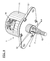
- FIG. 4 An overall perspective view of the linear drive 1 according to the invention Fig. 4
- the power supply of the linear drive 1 is effected by means of an electrical connection 18 penetrating the housing of the linear drive 1.
- the actuating rod 4 which is in axial operative connection with the functional element 13, is coupled by means of a coupling element 7.
- the fork legs 4.4 of the control rod 4 are guided by the formed as anti-rotation 12 breakthrough the drive bearing plate 5.1 form-fitting and supported.
Landscapes
- Engineering & Computer Science (AREA)
- Power Engineering (AREA)
- Transmission Devices (AREA)
- Connection Of Motors, Electrical Generators, Mechanical Devices, And The Like (AREA)
Description
- Die Erfindung betrifft einen Linearantrieb für Stellvorgänge zur Erzeugung translatorischer Vorschubbewegungen.
- Aus dem Stand der Technik sind Linearmotoren und Linearspindelmotoren als Linearantriebe bekannt. Während bei einem Linearmotor im Betrieb ein Wanderfeld zwischen dem stromdurchflossenen Primärteil und dem Reaktionsteil entsteht, wird beim Linearspindelmotor hingegen ein Drehfeld erzeugt, dass zur Umwandlung einer Rotationsbewegung des Rotors in eine Translationsbewegung der Gewindespindel genutzt wird.
- Linearspindelmotoren weisen einen stromdurchflossenen Stator und einen rotierenden Rotor auf, in dem ein Drehfeld induziert wird. Am oder im Rotor ist eine Gewindemutter angeordnet, die bei Rotation des Rotors eine passfähige Schraube oder Gewindespindel antreibt. Die axiale Vorschubbewegung der Spindel wird genutzt, um eine Stellbewegung eines Stellorgans auszuführen.
- Derartige Linearspindelmotoren werden in der Praxis im Bereich der Laborund Medizintechnik, der Sortiertechnik, der Lebensmittelindustrie, im Werkzeugmaschinenbau, in der Haus- und Gebäudetechnik, der Verpackungsindustrie sowie im Kraftfahrzeugbereich und der Unterhaltungselektronik eingesetzt.
- Beispielsweise wird im Bereich der Kraftfahrzeugtechnik die Verstellung der Scheinwerfer und im Bereich der Medizin- und Labortechnik das Öffnen und Schließen der Ventile oder anderer Drosseleinrichtungen durch Linearspindelmotoren realisiert.
- In der Druckschrift
US 6,223,971 B1 ist eine Antriebseinheit für eine Schweißmaschine offenbart. Hierbei besteht die Antriebeinheit aus bestrombaren Spulen und einem Rotor, der als Hohlwelle ausgebildet ist. Die Lagerung des Rotors erfolgt zweifach unter Verwendung von Radiallagern.
Der Rotor ist mittels Verbindungselementen mit einer Spindel gekoppelt. Ferner ist eine Stellstange mit Innengewinde vorgesehen, die auf der Spindel axial gleitet. Das axiale und außerhalb liegende Ende der Stellstange kann mit einem Funktionselement für Schweißarbeiten gekoppelt werden. Dabei ist die Stellstange vollständig über ihre Längserstreckung mit dem bereits erwähnten Innengewinde ausgestattet. An der Nodrive-Seite der Antriebseinheit ist ein nicht näher bezeichnetes Lagerschild angeordnet, welches von einem axialen Ende der Spindel durchdrungen wird. An diesem axialen Ende der Spindel ist eine Stellschraube angeordnet, um die Spindel und somit auch die die Spindel vollständig umschließende Stellstange im Bedarfsfall manuell bedienen zu können. - Der Nachteil dieser Linearspindelmotoren besteht vor allem darin, dass sie konstruktionsbedingt eine große Baulänge aufweisen und eine nicht unerhebliche Geräuschemission verursachen. Ursächlich dafür ist die Lagerung des Rotors mittels eines Wälzlagers und eines als Gleitlager ausgebildeten Notlagers zu nennen. Während der Bestromung des Linearmotors erzeugt das Wälzlager ein Kippmoment, was dazu führt, dass der Rotor nicht mehr parallel zum Stator geführt wird. Durch eine Kippung kann ein Schleifen des Rotors am Stator auftreten.
- Ein weiterer signifikanter Nachteil eines Bauteils des Linearspindelmotors, speziell der Gewindespindel, besteht darin, dass ihre Fertigung sehr aufwendig ist. Während die Gewindespindel im Wirkungsbereich der Gewindemutter ein Außengewinde aufweisen muss, ist sie im Bereich der Verdrehsicherung üblicherweise als Vierkant und außerhalb der Verdrehsicherung als kreisrunder Stab oder Stange ausgebildet.
- Es besteht seit geraumer Zeit bei Betreibern der Wunsch, Linearantriebe zu entwickeln, die zur Funktionserfüllung nur ein geringes Spaltmaß zwischen Rotor und Stator benötigen und dadurch einen höheren Wirkungsgrad sowie eine erhöhte Laufruhe sicherstellen.
- Aufgabe der Erfindung ist es, einen Linearantrieb für Stellvorgänge zu entwickeln, der bei gleichem Funktionsumfang preisgünstiger zu fertigen ist, der kompakter ausgebildet ist und der eine höhere Laufruhe aufweist.
- Diese Aufgabe wird erfindungsgemäß dadurch gelöst, indem der Rotor, der eine axial angeordnete sowie ein Außengewinde aufweisende Rotorwelle besitzt, glockenförmig mit einer offenen Stirnseite und einer geschlossenen Stirnseite ausgebildet ist, und eine die Rotorwelle mindestens teilweise einschließende und an der offenen Stirnseite des Rotors herausgeführte Stellstange für die Linearbewegung vorgesehen ist, deren im Rotor befindliches erstes Ende eine passfähige, auf der Rotorwelle mit Außengewinde aufsitzende Gewindemutter aufweist. Die Lagerung der Rotorwelle erfolgt durch an ihren axialen Enden über beide Stirnseiten des glockenförmigen Rotors hinaus reichende Gleitlagerzapfen, die jeweils in einem Gleitlager geführt sind und die an oder innerhalb der Lagerschilde platziert sind..
- Der glockenförmig ausgebildete Rotor erstreckt sich stirnseitig zwischen den Lagerschilden des Gehäuses, wobei die offene Stirnseite des Rotors in Richtung des Drive-Lagerschildes und die geschlossene Stirnseite des Rotors in Richtung des Nodrive-Lagerschildes weist. Innerhalb des glockenförmigen Rotors ist die mindestens an der offenen Stirnseite des Rotors überstehende Rotorwelle, die mit einem Außengewinde versehen ist, axial angeordnet, wobei die aus der offenen Stirnseite des Rotors herausragende und die Rotorwelle mindestens teilweise umschließende Stellstange mit ihrer Gewindemutter passfähig aufsitzt.
- Die gabelförmige bzw. hohlzylindersegmentförmige Stellstange, die in ihrer Längserstreckung die Rotorwelle mindestens teilweise einschließt, weist ein erstes Ende auf, das als Gewindemutter ausgebildet ist und mit der Rotorwelle in axialer Wirkverbindung steht. Der sich daran anschließende Bereich der Stellstange weist die Form von Hohlzylindersegmenten auf, deren Enden sich auch in eingezogener Position der Stellstange über den Bereich des Drive-Lagerschildes hinaus erstrecken.
- Das erste Ende und das zweite Ende der Stellstange sind kraftschlüssig und/oder formschlüssig durch mindestens einen Gabelschenkel oder durch Hohlzylindersegmente miteinander verbunden. In einer bevorzugten Ausführungsform sind jedoch aus Gründen einer gleichmäßigen Kraftverteilung und -übertragung die Gabelschenkel paarweise ausgebildet und diametral angeordnet.
- Der oder die Gabelschenkel durchdringen das Drive-Lagerschild, so dass eine Linearbewegung in Richtung des Drive-Lagerschilds realisiert werden kann.
- Erfindungsgemäß ist der Querschnitt des oder der Gabelschenkel oder der Hohlzylindersegmente der Stellstange der Querschnittsform eines Durchbruchs im Drive-Lagerschildes angepasst, so dass die Stellstange torsionssicher und formschlüssig mit Spielpassung im Durchbruch des Drive-Lagerschildes geführt und gehaltert ist. Der Durchbruch des Drive-Lagerschild ist demnach als Verdrehsicherung und Linearführung ausgebildet, um eine Verkippung der Stellstange (Gewindemutter) zu verhindern.
- Die an dem Rotor befestigte Rotorwelle ist im Gegensatz zu herkömmlichen Rotoren mittels zweier identisch ausgebildeter Gleitlager gelagert, was mehrere Vorteile mit sich bringt. Zum einen kann auf ein kostenintensives Wälzlager verzichtet werden und zum anderen neigt der Rotor bei der Rotation zu keinem Kippspiel. Die Rotorwelle besitzt durch die stabile Lagerung nur einen Freiheitsgrad. Die axialen Enden der Rotorwelle sind als Gleitlagerzapfen ausgebildet, die über die Stirnseiten des glockenförmigen Rotors hinaus reichen. Ein weiterer nicht zu unterschätzender Vorteil dieser Gleitlager besteht darin, dass der Luftspalt zwischen dem Stator und dem Rotor in Richtung der Längserstreckung des Rotors des Linearantriebs konstant ausgebildet ist. Der Luftspalt beträgt zwischen 0,1 mm und 0,4 mm. Dadurch, dass die Gleitlager zu keinem Kippspiel neigen, bleibt dieser Luftspalt zwischen Stator und Rotor auch während der Bestromung des Linearantriebs konstant, was zu einer erheblichen Geräuschreduzierung und damit Laufruhe gegenüber den Linearantrieben aus dem Stand der Technik führt.
- Die Gleitlager sind als kombinierte Quer- und Längslager ausgebildet und können somit radiale und axiale Kräfte aufnehmen. Dem radialen Kraftangriff der Rotorwelle wird mittels zweier Lagerschalen oder einer Lagerbuchse begegnet, in denen die Mantelflächen der Endbereiche der Rotorwelle gleiten. Diese Endbereiche sind bevorzugt als Gleitlagerzapfen ausgebildet. Zur Ableitung der axialen Kräfte, die u.a. durch das axiale Bewegungsspiel der Rotorwelle erzeugt werden, werden Axiallager eingesetzt. Diese Axiallager weisen vorzugsweise Lagerplatten, beispielsweise aus Stein oder Metall auf, die die Stirnseiten der Gleitlagerzapfen der Rotorwelle einfassen und kontaktieren. Diese Lagerplatten sind mit jeweils einer ebenen und einer balligen Fläche ausgebildet.
- In einer bevorzugten Ausgestaltung der Erfindung wird anstelle einer Spurplatte eine Kugel eingesetzt. Kugeln sind auf Grund ihrer Formgebung besonders gut geeignet, um die bei der Rotation auftretende Hertzsche Pressung, die zwischen den Gleitlagerzapfen und dem Gleitlager auftritt, zu verkleinern. Zudem können handelsübliche Metallkugeln eingesetzt werden, die wesentlich preiswerter als Lagerplatten zu fertigen sind.
- Die Gleitlager können aus allen üblichen Lagermaterialien, wie z. B. Sinter-Bronze, Kunststoff oder Messing gefertigt sein. Um bei hohem Lastspiel Abrieb an den Gleitlagerzapfen der Rotorwelle zu vermeiden und gute Reibwerte zu erzielen, sind diese vorzugsweise aus härteren Material wie die Gleitlager gefertigt.
- Nach der Konzeption der Erfindung wird die lineare Stellbewegung der Stellstange über eine Koppelstelle auf ein anwendungsspezifisches Funktionselement übertragen. Die Koppelstelle ist aus Gründen der Auswechselbarkeit vorzugsweise außerhalb des Gehäuses angeordnet.
- Die Stellstange erstreckt sich demnach vom Gehäuseinneren bis zur Koppelstelle, während dessen sich das Funktionselement von der Koppelstelle bis zu einem Stellorgan erstreckt.
- Die Koppelstelle kann als separates Bauteil ausgebildet oder an die Stellstange angeformt sein. Als besonders vorteilhaft in Bezug auf die axiale Kraftübertragung hat sich erwiesen, wenn die Stellstange mittels Bajonett- oder Schnappverbindungen oder vergleichbaren formschlüssigen Verbindungselementen mit dem Funktionselement in Eingriff gebracht wird. In einer bevorzugten Ausführungsform werden Klammern eingesetzt, welche hohe Zug- und Schubkräfte übertragen.
- Ein besonderer Vorteil des erfindungsgemäßen Linearantriebs besteht darin, dass das mit einer Gewindemutter ausgebildete erste Ende der Stellstange nur innerhalb des glockenförmigen Rotors axial beweglich geführt wird, was zu einer deutlichen Baulängenreduzierung des Linearantriebs beiträgt.
- Die signifikanten Vorteile und Merkmale der Erfindung gegenüber dem Stand der Technik sind im Wesentlichen:
- kompaktere Bauweise und kürzere Baulänge gegenüber herkömmlichen Linearspindelmotoren, da die Stellstange nur innerhalb des glockenförmigen Rotors bzw. des Drive-Lagerschildes axial beweglich ausgebildet ist, wobei durch eine Verlängerung des Drive-Lagerschildes eine Verlängerung des Stellweges der Stellstange erzielt,
- durch die Trennung der Axial- und Radiallagerung ist eine besonders preisgünstige Ausführung der Lagerelemente möglich,
- Luftspalt zwischen Rotor und Stator ist in Richtung der Längserstreckung des Linearmotors konstant, da anstelle eines Wälzlagers (Gefährdung durch Kippspiel !) zwei Gleitlager angeordnet sind, womit eine höhere Laufruhe entsteht und
- lineare Stellbewegung der Stellstange wird über eine Koppelstelle auf ein anwendungsspezifisches Funktionselement übertragen, wobei die Koppelstelle außerhalb des Linearmotors angeordnet ist und damit die Möglichkeit besteht, anwendungsspezifische Funktionselemente in besonders vorteilhafter Weise anzukoppeln, ohne die gesamte Stellstange oder wie bislang, die gesamte Spindel oder Schraube, auszutauschen zu müssen.
- Verschiedene Lösungen und Vorteile der Erfindung erschließen sich dem Fachmann des Weiteren aus der folgenden detaillierten Beschreibung einer bevorzugten Ausführungsform im Hinblick auf die anliegenden Zeichnungen; in diesen zeigen:
- Fig. 1a
- schematische Darstellung eines Linearspindelmotors aus dem Stand der Technik im Querschnitt
- Fig. 1b
- schematische Darstellung des Drive-Lagerschilds des Linearspindelmotors aus dem Stand der Technik im Axialschnitt
- Fig. 1c
- schematische Darstellung des Drive-Lagerschilds des Linearspindelmotors aus dem Stand der Technik im Querschnitt
- Fig. 2a
- schematische Darstellung des erfindungsgemäßen Linearantriebs im Querschnitt
- Fig. 2b
- schematische Darstellung des Drive-Lagerschilds des erfindungsgemäßen Linearantriebs im Axialschnitt
- Fig. 2c
- schematische Darstellung des Drive-Lagerschilds des erfindungsgemäßen Linearantriebs im Querschnitt
- Fig. 3
- Detaildarstellung des erfindungsgemäßen Linearantriebs
- Fig. 4
- perspektivische Gesamtdarstellung des erfindungsgemäßen Linearantriebs
- Die
Fig. 1 a zeigt eine schematische Darstellung eines Linearspindelmotors 14 aus dem Stand der Technik im Querschnitt. Der Linearspindelmotor 14 umfasst den Stator 10, das Gehäuse 11, die stirnseitig das Gehäuse 11 umfassenden Lagerschilde 5, den Rotor 2 mit angeschlossener Gewindemutter 4.3, die Gewindespindel 15 und die Stellstange 4. Die Gewindespindel 15 weist ein Außengewinde 3.1 auf, das sich maximal bis zum Drive-Lagerschild 5.1 erstreckt. Die Gewindespindel 15 steht kraft- und/oder formschlüssig mit einer Stellstange 4 in axialer Wirkverbindung. In Stellrichtung ist die Stellstange 4 unmittelbar im Bereich des Drive-Lagerschildes 5.1 als Vierkant ausgebildet und wird von einer des Querschnitts dieses Vierkants entsprechenden Durchführung durch Verdrehen gesichert. Diese Durchführung ist als Verdrehsicherung 8 ausgeführt. In Stellrichtung ist die Stellstange 4 im Bereich außerhalb der Verdrehsicherung 8 als Stab oder als Stange mit einer glatten Oberfläche ausgebildet, wobei das außerhalb des Gehäuses 11 befindliche axiale Ende der Stellstange 4 gleichzeitig als ein nicht näher dargestelltes Funktionselement 13 ausgebildet ist. Die Lagerung des zylinderförmigen Rotors 2 erfolgt mittelbar über die Stellstange 4 und die Gewindespindel 15. - Die Gewindespindel 15 ist dabei mittels eines Notlagers 17 und die mit dieser Gewindespindel 15 in axialer Wirkverbindung stehende Stellstange 4 mittels eines Wälzlagers gelagert.
Das Wälzlager 16 ist üblicherweise im Bereich des Drive-Lagerschildes 5.1 angeordnet, während dessen das als Gleitlager ausgebildete Notlager 17 im Bereich der Nodrive-Lagerschildes 5.2 angeordnet ist. Das Notlager 17 ist derart ausgebildet, um die das axiale Bewegungsspiel der Gewindespindel 15 in jedem Betriebszustand sicherzustellen. Als Betriebszustand soll jede Stellung der Gewindespindel 15 verstanden werden, die sie während ihrer Linearbewegung einnehmen kann. Wie inFig. 2b ersichtlich, ist das Nodrive-Lagerschild 5.2 konzentrisch abgestuft und weist damit keine ebene Außenfläche auf. Die axiale Baulänge des Linearspindelmotors 14 wird durch den maximal möglichen Stellweg der Gewindespindel 15 und Stellstange 4 bestimmt. - Die
Fig. 1b und 1c illustrieren eine schematische Darstellung des Drive-Lagerschilds 5.1 eines Linearspindelmotors 14 aus dem Stand der Technik im Axial- und Querschnitt. Das Drive-Lagerschild 5.1 weist einen zentralen Durchbruch in Form einer kreisrunden Bohrung auf. Der Durchmesser der Bohrung entspricht dem Außendurchmesser einer Gewindespindel 15, die durch die Bohrung axial geführt wird. Gegebenenfalls kann die Bohrung eine ringförmige Dichtung aufweisen. Die außerhalb des Drive-Lagerschildes 5.1 angeordnete Verdrehsicherung 8 ist mit einem koaxialen Kreis nur angedeutet. - Die
Fig. 2a zeigt eine schematische Darstellung des erfindungsgemäßen Linearantriebs 1 im Querschnitt. Besonders auffällig ist, dass die Gewindemutter nicht wie bei herkömmlichen Linearspindelmotoren 14 mit dem Rotor 2 verbunden ist und damit einer Relativbewegung gegenüber dem Stator 10 unterliegt, sondern an einem Ende der gabelförmigen bzw. hohlzylindersegmentförmigen axial beweglichen Stellstange 4 innerhalb des Linearantriebs 1 befestigt ist, und damit einer Absolutbewegung gegenüber dem Stator 10 unterworfen wird. Ein erstes Ende 4.2 der Stellstange 4, das innerhalb des Rotors 2 angeordnet ist, ist zylinderförmig ausgebildet und weist eine Gewindemutter auf, die kraft und formschlüssig von einer Rotorwelle 3 axial angetrieben wird. Ein zweites Ende 4.3 der Stellstange 4 weist im Querschnitt zwei diametral zueinander angeordnete Segmente eines Kreisrings auf, wobei die beiden Enden 4.2, 4.3 der Stellstange 4 durch zwei Gabelschenkel bzw. Hohlsegmente 4.4 miteinander verbunden sind. Diese Gabelschenkel 4.4 sind durch den Durchbruch des Drive-Lagerschilds 5.1 geführt. Das außerhalb des Gehäuses befindliche zweite Ende 4.3 der gabelförmigen Stellstange 4 ist zugleich als Koppelstelle 7 ausgebildet. Die dargestellte Koppelstelle 7 steht mit einem Funktionselement 13 in axialer Wirkverbindung, wobei das Funktionselement 13 an die anwendungsspezifischen Aufgaben in besonderer Weise in seiner Form ausgebildet sein kann. Beispielsweise kann dieses Funktionselement 13 an seinem der Koppelstelle 7 abgewandten Ende eine Kugel oder einen als Mitnehmer ausgebildeten Flansch aufweisen. Es ist weiterhin erkennbar, dass die Rotorwelle 3 mit dem Rotor 2 fest verbunden ist. Die Rotorwelle 3 ist an ihren axialen Enden mittels zweier Gleitlager 6 gelagert. Im Gegensatz zu einem herkömmlichen Wälzlager 16 in Verbindung mit einem Notlager 17 gemäßFig. 1a ist die Rotorwelle 3 nun stabiler gelagert und neigt nicht zu einem Kippspiel.
DieFig. 2b und 2c illustrieren eine schematische Darstellung des Drive-Lagerschilds 5.1 des erfindungsgemäßen Linearantriebs 1 im Axial- und Querschnitt. Es ist erkennbar, dass das Drive-Lagerschild 5.1 einen zentralen Durchbruch aufweist, durch den die in derFig. 2a dargestellte gabelförmige Stellstange 4 geführt und gehaltert wird. Der Durchbruch ist gleichzeitig als Verdrehsicherung 12 ausgebildet. Die Form des Durchbruchs entspricht dem Querschnitt der Gabelschenkel 4.4 der Stellstange 4. Die durch das Lagerschild 5.1 austretenden Gabelschenkel 4.4 bzw. Hohlzylindersegmente werden außerhalb des Gehäuses 11 durch ein hier dargestelltes Koppelelement 7 oder durch einen nichtdargestellten Steg (im Querschnitt Doppel-T-Form aufweisend) miteinander verbunden. Zwischen Stellstange 4 und Durchbruch kann eine nichtdargestellte Dichtung ausgebildet sein, die den Linearantrieb 1 gegenüber der Umgebung wassergeschützt abdichtet. Somit kann der Linearantrieb 1 auch in spritzwassergefährdeten Bereichen problemlos eingesetzt werden. - In
Fig. 3 ist der erfindungsgemäße Linearantrieb 1 im Axialschnitt dargestellt. Der Linearantrieb 1 weist koaxial angeordnete Statorspulen 10, ein Gehäuse 11, einen axial angeordneten Rotor 2 mit Rotorwelle 3, eine mit der Rotorwelle 3 in Wirkverbindung stehende Stellstange 4 sowie das Gehäuse 11 stirnseitig begrenzende Lagerschilde 5 auf. Der Rotor 2 ist glockenförmig mit einer axial angeordneten Rotorwelle 3 mit Außengewinde 3.1 ausgebildet. Der Rotor 2 erstreckt sich innerhalb des Gehäuses 11 des Linearantriebes 1 zwischen den Lagerschilden 5 und weist eine offene Stirnseite 2.1 und eine geschlossene Stirnseite 2.2 auf. Die offene Stirnseite 2.1 des Rotors 2 ist dabei in Richtung des Drive-Lagerschildes 5.1 und die geschlossene Stirnseite 2.2 des Rotors 2 in Richtung des Nodrive-Lagerschildes 5.2 ausgebildet.
An der geschlossenen Stirnseite 2.2 des Rotors 2 ist die Rotorwelle 3 befestigt, die in ihrer Längserstreckung über die Stirnseiten 2.1, 2.2 des glockenförmigen Rotors 2 hinaus reicht. Die axialen Enden der Rotorwelle 3 sind als Gleitlagerzapfen 3.2 ausgebildet, die in die an den Lagerschilden 5 angeordneten Gleitlagern 6 eingreifen. Jedes Lagerschild 5.1, 5.2 weist jeweils ein Gleitlager 6 auf. Die Gleitlager 6 sind als kombinierte Quer- und Längslager derart ausgebildet, dass sie radiale und axiale Kräfte gleichermaßen aufnehmen können. Hierbei wurde ein herkömmliches Gleitlager 6, welches Lagerbuchsen oder Lagerschalen aufweist, um eine handelsübliche Kugel ergänzt. Diese Kugel ist innerhalb des Gleitlagers 6 angeordnet und kontaktiert stirnseitig die ebenen axialen Enden der Gleitlagerzapfen 3.2. Anstelle einer Kugel kann auch eine Lagerplatte eingesetzt werden, die eine ebene und eine ballige Fläche aufweist. Dadurch, dass die beiden Gleitlager 6 jeweils radiale und axiale Kräfte aufnehmen können, konnte auf ein teures Wälzlager 16 verzichtet werden. Ferner bildet sich durch die beidseitige Lagerung der Rotorwelle 3 mit gleichartigen Gleitlagern 6 ein konstanter Luftspalt 9 zwischen Stator 10 und Rotor 2 aus. Diese Konstanz bezieht sich einerseits auf den Abstand zwischen Stator 10 und Rotor 2 in Längserstreckung des Rotors 2, wobei dieser Luftspalt 9 bevorzugt 0,2 mm beträgt. Andererseits verändert sich dieser Luftspalt 9 auch nicht im Lastzustand, also bei Strombeaufschlagung des Linearantriebs 1. Die ein Außengewinde 3.1 aufweisende Rotorwelle 3 steht erfindungsgemäß mit einer ein passfähiges Innengewinde 4.1 aufweisenden Stellstange 4 derart in Wirkverbindung, dass eine Rotationsbewegung in eine translatorische Vorschubbewegung umgesetzt wird. Das erste Ende 4.2 der Stellstange 4 ist zylinderförmig mit einer Gewindemutter ausgebildet und der sich daran anschließende Bereich mit dem zweiten Ende 4.3 der Stellstange 4 weist die Form von Hohlzylindersegmenten, hier in der Ausführung als zwei diametral zueinander angeordnete Segmente eines Kreisrings, auf. Diese Hohlzylindersegmente 4.4 verbinden als Gabelschenkel 4.4 beide Enden 4.2, 4.3 der Stellstange 4 miteinander.
Das zylinderförmige erste Ende 4.2 der Stellstange 4 greift form- und kraftschlüssig in die Rotorwelle 3 ein, während dessen das hohlzylinderförmige zweite Ende 4.3 der Stellstange 4 außerhalb des Gehäuses 11 des Linearantriebs 1 mit einem Funktionselement 13 gekoppelt ist. Das Drive-Lagerschild 5.1, durch welches die Gabelschenkel 4.4 der Stellstange 4 geführt sind, ist mit einem der Querschnittsform der Gabelschenkel 4.4 entsprechenden Durchbruch ausgebildet. Dieser Durchbruch weist gemäßFig. 3 zwei identische Schlitze bzw. Nuten auf, wobei diese Schlitze bzw. Nuten diametral zueinander angeordnet und in einem definierten Radius um das Gleitlager 6 gekrümmt ausgebildet sind. Der Durchbruch dient nicht nur als Führung der Stellstange 4, sondern auch als Verdrehsicherung 8. Da die Gabelschenkel 4.4 der Stellstange 4 und der Durchbruch gemäß denFig. 2a bis 2c einen identischen Querschnitt aufweisen, wird die Stellstange 4 während ihrer Axialbewegung folglich geführt und gehaltert. - Die Stellstange 4 steht in axialer Wirkverbindung mit einem nicht näher dargestellten Funktionselement 13, wobei die Koppelstelle 7 zwischen der Stellstange 4 und des Funktionselements 13 außerhalb des Gehäuses 11 des Linearantriebs 1 ausgebildet ist. Diese Koppelstelle 7 dient als Schnittstelle zwischen der Stellstange 4 und dem Funktionselement 13. Das Funktionselement 13 dient verschiedenen Aufgaben, beispielsweise zur Öffnen und Schließen eines Ventils oder der Verstellung eines Scheinwerfers bei Kraftfahrzeugen.
Der Linearantrieb 1 ist damit universell für verschiedene Aufgabenfelder einsetzbar, denn eine Adaption des erfindungsgemäßen Linearantriebs 1 an die gewünschte Aufgabenstellung erfordert nur das Ankoppeln eines entsprechend ausgebildeten Funktionselements 13 an das außerhalb des Gehäuses des Linearantriebs 1 befindliche zweite Ende 4.3 der Stellstange 4 mittels der Koppelstelle 7. Diese ist bevorzugt als Bajonett ausgebildet, um hohe Montagekräfte auf den Rotor 2 zu vermeiden. - Eine perspektivische Gesamtdarstellung des erfindungsgemäßen Linearantriebs 1 stellt
Fig. 4 dar. Die Stromversorgung des Linearantriebs 1 erfolgt mittels eines das Gehäuse des Linearantriebs 1 durchdringenden elektrischen Anschlusses 18. Es ist erkennbar, dass die mit dem Funktionselement 13 in axialer Wirkverbindung stehende Stellstange 4 mittels eines Koppelelements 7 gekoppelt ist. Die Gabelschenkel 4.4 der Stellstange 4 sind durch den als Verdrehsicherung 12 ausgebildeten Durchbruch das Drive-Lagerschild 5.1 formschlüssig geführt und gehaltert. -
- 1
- Linearantrieb
- 2
- Rotor
- 2.1
- offene Stirnseite des Rotors
- 2.2
- geschlossene Stirnseite des Rotors
- 3
- Rotorwelle
- 3.1
- Außengewinde
- 3.2
- Gleitlagerzapfen
- 4
- Stellstange
- 4.1
- Innengewinde
- 4.2
- erstes Ende der Stellstange
- 4.3
- zweites Ende der Stellstange
- 4.4
- Gabelschenkel, Hohlzylindersegmente
- 5
- Lagerschilde
- 5.1
- Drive-Lagerschild
- 5.2
- Nodrive-Lagerschild
- 6
- Gleitlager
- 6.1
- Kugel
- 7
- Koppelstelle
- 8
- Verdrehsicherung im Stand der Technik
- 9
- Luftspalt
- 10
- Stator
- 11
- Gehäuse
- 12
- Verdrehsicherung, Durchbruch
- 13
- Funktionselement
- 14
- Linearspindelmotor
- 15
- Gewindespindel
- 16
- Wälzlager
- 17
- Notlager
- 18
- elektrischer Anschluss
Claims (8)
- Linearantrieb für Stellvorgänge zur Erzeugung translatorischer Vorschubbewegungen, mindestens aufweisend ein Gehäuse (11), Lagerschilde (5), die dieses Gehäuse (11) stirnseitig begrenzen, einen Stator (10), einen Rotor (2) mit einer axial angeordneten mit einem Außengewinde (3.1) ausgebildeten Rotorwelle (3), eine Gewindemutter und eine bewegliche Schraube/Spindel, dadurch gekennzeichnet, dass der Rotor (2) glockenförmig mit einer offenen Stirnseite (2.1) und einer geschlossenen Stirnseite (2.2) ausgebildet ist, und eine die Rotorwelle (3) mindestens teilweise einschließende und an der offenen Stirnseite (2.1) des Rotors (2) herausgeführte Stellstange (4) für die Linearbewegung vorgesehen ist, wobei deren im Rotor befindliches erstes Ende (4.2) eine passfähige auf der Rotorwelle (3) mit Außengewinde (3.1) aufsitzende Gewindemutter aufweist, und die Rotorwelle an ihren axialen Enden über beide Stirnseiten (2.1, 2.2) des glockenförmigen Rotors (2) hinaus reichende Gleitlagerzapfen (3.2) aufweist, die jeweils in einem Gleitlager (6) geführt sind und die an oder innerhalb der Lagerschilde (5) platziert sind.
- Linearantrieb nach Anspruch 1, dadurch gekennzeichnet, dass die Stellstange (4) gabelförmig oder hohlsegmentförmig ausgebildet ist und das erste Ende (4.2) sowie das zweite Ende (4.3) der Stellstange (4) durch mindestens einen Gabelschenkel (4.4) miteinander verbunden sind.
- Linearantrieb nach Anspruch 1 oder 2, dadurch gekennzeichnet, dass der oder die als Hohlzylindersegmente ausgebildeten Gabelschenkel (4.4) durch einen dem Querschnitt des oder der Gabelschenkel(s) (4.4) angepassten Durchbruch (12) des Drive-Lagerschildes (5.1) torsionssicher und formschlüssig mit einer Spielpassung geführt sind.
- Linearantrieb nach einem der Ansprüche 1 bis 3, dadurch gekennzeichnet, dass der Durchbruch des Drive-Lagerschild (5.1) als Verdrehsicherung (8) ausgebildet ist.
- Linearantrieb nach Anspruch 1, dadurch gekennzeichnet, dass die Mantelflächen der Gleitlagerzapfen (3.2) der Rotorwelle (3) in einer Lagerbuchse oder in Lagerschalen des Gleitlagers (6) gleiten und die Stirnseiten der Gleitlagerzapfen durch Lagerplatten axial im Gleitlager (6) eingefasst sind.
- Linearantrieb nach Anspruch 5, dadurch gekennzeichnet, dass anstelle einer Lagerplatte eine Kugel verwendet wird, die stirnseitig den Gleitlagerzapfen (3.2) einfasst und kontaktiert.
- Linearantrieb nach einem der Ansprüche 1 bis 6, dadurch gekennzeichnet, dass der Luftspalt (9) zwischen Stator (10) und Rotor (2) in Richtung der Längserstreckung des Rotors (2) konstant ausgebildet ist und zwischen 0,1 und 0,3 mm beträgt.
- Linearantrieb nach einem der Ansprüche 1 bis 7, dadurch gekennzeichnet, dass die Stellstange (4) in axialer Wirkverbindung mit einem Funktionselement (13) gekoppelt ist, wobei die Koppelstelle (7) zwischen der Stellstange (4) und dem Funktionselement (13) außerhalb des Gehäuses (11) des Linearantriebs (1) ausgebildet ist.
Applications Claiming Priority (2)
| Application Number | Priority Date | Filing Date | Title |
|---|---|---|---|
| DE10332389 | 2003-07-11 | ||
| DE10332389A DE10332389B4 (de) | 2003-07-11 | 2003-07-11 | Linearantrieb |
Publications (3)
| Publication Number | Publication Date |
|---|---|
| EP1496600A2 EP1496600A2 (de) | 2005-01-12 |
| EP1496600A3 EP1496600A3 (de) | 2006-10-11 |
| EP1496600B1 true EP1496600B1 (de) | 2012-05-02 |
Family
ID=33441768
Family Applications (1)
| Application Number | Title | Priority Date | Filing Date |
|---|---|---|---|
| EP04015931A Expired - Lifetime EP1496600B1 (de) | 2003-07-11 | 2004-07-07 | Linearantrieb |
Country Status (4)
| Country | Link |
|---|---|
| EP (1) | EP1496600B1 (de) |
| AT (1) | ATE556477T1 (de) |
| DE (1) | DE10332389B4 (de) |
| ES (1) | ES2385478T3 (de) |
Families Citing this family (10)
| Publication number | Priority date | Publication date | Assignee | Title |
|---|---|---|---|---|
| DE102009010085B3 (de) * | 2009-02-24 | 2010-07-01 | Saia-Burgess Dresden Gmbh | Linear-Aktuator |
| EP2249461B1 (de) | 2009-05-05 | 2017-02-01 | PARKER-ORIGA GmbH | Elektromechanischer Linearantrieb |
| CN104852508A (zh) * | 2015-05-15 | 2015-08-19 | 燕山大学 | 一种双出杆电动缸 |
| DE102017102631B4 (de) | 2017-02-09 | 2020-06-25 | Johnson Electric Germany GmbH & Co. KG | Linearschrittmotor mit einer in einem Gehäuse längsverschieblichen Stellstange |
| DE102017102629B4 (de) | 2017-02-09 | 2022-12-29 | Johnson Electric Germany GmbH & Co. KG | Stator für einen Linearschrittmotor und Verfahren zu seiner Herstellung |
| DE202017100708U1 (de) | 2017-02-09 | 2017-05-03 | Johnson Electric Germany GmbH & Co. KG | Linearschrittmotor mit einer Rotorspindel für einen linear geführten Stellantrieb |
| DE102017102630B4 (de) | 2017-02-09 | 2020-08-06 | Johnson Electric Germany GmbH & Co. KG | Linearschrittmotor, sowie Vorrichtung und Verfahren zur Herstellung eines Linearschrittmotors mit kugelgelagerter Rotorwelle |
| DE102017102628B4 (de) | 2017-02-09 | 2020-06-25 | Johnson Electric Germany GmbH & Co. KG | Linearschrittmotor mit einem koppelbaren Funktionskopf |
| US10666124B2 (en) * | 2017-02-09 | 2020-05-26 | Johnson Electric International AG | Linear stepper motor and valve utilizing the same |
| DE102019122140A1 (de) * | 2019-08-17 | 2021-02-18 | Johnson Electric Germany GmbH & Co. KG | Anordnung zur Geräuschminderung bei Linearantrieben |
Family Cites Families (8)
| Publication number | Priority date | Publication date | Assignee | Title |
|---|---|---|---|---|
| US3548227A (en) * | 1969-04-03 | 1970-12-15 | Usm Corp | Electromagnetic linear drives |
| JPS62203528A (ja) * | 1986-02-28 | 1987-09-08 | Mitsubishi Heavy Ind Ltd | ステツプモ−タ−アクチユエ−タ− |
| FR2630595B1 (fr) * | 1988-04-26 | 1990-08-24 | Roudaut Philippe | Pince electrique a maintien magnetique |
| DE4107053A1 (de) * | 1991-03-06 | 1992-09-10 | Bosch Gmbh Robert | Stelleinrichtung fuer ein drosselorgan einer brennkraftmaschine |
| DE19807147A1 (de) * | 1998-02-20 | 1999-08-26 | Pierburg Ag | Linearsteller |
| CA2321585C (en) * | 1998-02-26 | 2007-09-04 | Tri-Tech, Inc. | Linear/rotary motor and method of use |
| DE29818691U1 (de) * | 1998-10-21 | 1999-02-11 | OKIN Gesellschaft für Antriebstechnik mbH & Co. KG, 51645 Gummersbach | Linearantrieb |
| US6223971B1 (en) * | 1999-11-24 | 2001-05-01 | Obara Corporation | Driving unit of a welding equipment |
-
2003
- 2003-07-11 DE DE10332389A patent/DE10332389B4/de not_active Expired - Fee Related
-
2004
- 2004-07-07 AT AT04015931T patent/ATE556477T1/de active
- 2004-07-07 EP EP04015931A patent/EP1496600B1/de not_active Expired - Lifetime
- 2004-07-07 ES ES04015931T patent/ES2385478T3/es not_active Expired - Lifetime
Also Published As
| Publication number | Publication date |
|---|---|
| EP1496600A2 (de) | 2005-01-12 |
| EP1496600A3 (de) | 2006-10-11 |
| DE10332389A1 (de) | 2005-03-10 |
| ATE556477T1 (de) | 2012-05-15 |
| DE10332389B4 (de) | 2006-05-24 |
| ES2385478T3 (es) | 2012-07-25 |
Similar Documents
| Publication | Publication Date | Title |
|---|---|---|
| DE10332389B4 (de) | Linearantrieb | |
| DE102013217161A1 (de) | Lineareinheit sowie Verfahren zur Herstellung einer Lineareinheit | |
| WO2010043320A1 (de) | Elektromagnetische stellvorrichtung | |
| EP1905147B1 (de) | Getriebemotor | |
| DE102022106373A1 (de) | Linearantrieb | |
| DE102009035632B3 (de) | Nockenwelle mit Nockenwellenversteller | |
| WO2006111456A1 (de) | Servolenkung mit elastisch gelagertem kugelumlauf-spindel-getriebe | |
| DE202023104451U1 (de) | Bremseinrichtung für Fahrzeug | |
| EP0647542A1 (de) | Stellantrieb mit einem elektrischen Antriebsmotor und einem diesem nachgeordneten Getriebe | |
| DE102006024841B4 (de) | Elktromagnetische Stellvorrichtung | |
| DE102015212643A1 (de) | Gewindetrieb | |
| DE102023105784A1 (de) | Pumpenventilanordnung | |
| EP2252774B1 (de) | Elektromagnetische nockenwellen-verstellvorrichtung | |
| DE19948265A1 (de) | Linearstellglied | |
| DE19847016A1 (de) | Vorrichtung zum Bewegen eines Teils, insbesondere in einem Kraftfahrzeug, mit einem Verstellmechanismus | |
| EP3405698B1 (de) | Aktuator mit hohlschnecke | |
| EP2997646A1 (de) | Antriebseinrichtung, insbesondere stelleinrichtung in einem fahrzeug | |
| DE102015219502A1 (de) | Antriebseinrichtung | |
| DE102007038264A1 (de) | Aktiver Stabilisator zur Wankstabilisierung | |
| DE102018126350A1 (de) | Lagerung eines Linearaktors für ein Fahrzeug | |
| DE102011054085B3 (de) | Stellvorrichtung | |
| EP2072861B1 (de) | Verdrehsicherung mit Toleranzausgleich | |
| WO2022008243A1 (de) | Aktuator einer steer-by-wire-lenkvorrichtung eines kraftfahrzeuges sowie verfahren zur montage eines aktuators einer steer-by-wire-lenkvorrichtung | |
| DE102016216914A1 (de) | Elektromechanischer Betätigungsaktor mit Kardangelenk für Drehübertragung auf Spindelmutter | |
| DE102006030032A1 (de) | Vorrichtung zur Betätigung eines Stell- oder Schaltelementes |
Legal Events
| Date | Code | Title | Description |
|---|---|---|---|
| PUAI | Public reference made under article 153(3) epc to a published international application that has entered the european phase |
Free format text: ORIGINAL CODE: 0009012 |
|
| AK | Designated contracting states |
Kind code of ref document: A2 Designated state(s): AT BE BG CH CY CZ DE DK EE ES FI FR GB GR HU IE IT LI LU MC NL PL PT RO SE SI SK TR |
|
| AX | Request for extension of the european patent |
Extension state: AL HR LT LV MK |
|
| PUAL | Search report despatched |
Free format text: ORIGINAL CODE: 0009013 |
|
| AK | Designated contracting states |
Kind code of ref document: A3 Designated state(s): AT BE BG CH CY CZ DE DK EE ES FI FR GB GR HU IE IT LI LU MC NL PL PT RO SE SI SK TR |
|
| AX | Request for extension of the european patent |
Extension state: AL HR LT LV MK |
|
| 17P | Request for examination filed |
Effective date: 20061214 |
|
| AKX | Designation fees paid |
Designated state(s): AT BE BG CH CY CZ DE DK EE ES FI FR GB GR HU IE IT LI LU MC NL PL PT RO SE SI SK TR |
|
| GRAP | Despatch of communication of intention to grant a patent |
Free format text: ORIGINAL CODE: EPIDOSNIGR1 |
|
| GRAS | Grant fee paid |
Free format text: ORIGINAL CODE: EPIDOSNIGR3 |
|
| GRAA | (expected) grant |
Free format text: ORIGINAL CODE: 0009210 |
|
| AK | Designated contracting states |
Kind code of ref document: B1 Designated state(s): AT BE BG CH CY CZ DE DK EE ES FI FR GB GR HU IE IT LI LU MC NL PL PT RO SE SI SK TR |
|
| REG | Reference to a national code |
Ref country code: GB Ref legal event code: FG4D Free format text: NOT ENGLISH |
|
| REG | Reference to a national code |
Ref country code: CH Ref legal event code: EP Ref country code: AT Ref legal event code: REF Ref document number: 556477 Country of ref document: AT Kind code of ref document: T Effective date: 20120515 |
|
| REG | Reference to a national code |
Ref country code: IE Ref legal event code: FG4D Free format text: LANGUAGE OF EP DOCUMENT: GERMAN |
|
| REG | Reference to a national code |
Ref country code: DE Ref legal event code: R096 Ref document number: 502004013483 Country of ref document: DE Effective date: 20120621 |
|
| REG | Reference to a national code |
Ref country code: ES Ref legal event code: FG2A Ref document number: 2385478 Country of ref document: ES Kind code of ref document: T3 Effective date: 20120725 |
|
| REG | Reference to a national code |
Ref country code: NL Ref legal event code: T3 |
|
| PG25 | Lapsed in a contracting state [announced via postgrant information from national office to epo] |
Ref country code: FI Free format text: LAPSE BECAUSE OF FAILURE TO SUBMIT A TRANSLATION OF THE DESCRIPTION OR TO PAY THE FEE WITHIN THE PRESCRIBED TIME-LIMIT Effective date: 20120502 Ref country code: CY Free format text: LAPSE BECAUSE OF FAILURE TO SUBMIT A TRANSLATION OF THE DESCRIPTION OR TO PAY THE FEE WITHIN THE PRESCRIBED TIME-LIMIT Effective date: 20120502 Ref country code: PL Free format text: LAPSE BECAUSE OF FAILURE TO SUBMIT A TRANSLATION OF THE DESCRIPTION OR TO PAY THE FEE WITHIN THE PRESCRIBED TIME-LIMIT Effective date: 20120502 Ref country code: SE Free format text: LAPSE BECAUSE OF FAILURE TO SUBMIT A TRANSLATION OF THE DESCRIPTION OR TO PAY THE FEE WITHIN THE PRESCRIBED TIME-LIMIT Effective date: 20120502 |
|
| PG25 | Lapsed in a contracting state [announced via postgrant information from national office to epo] |
Ref country code: GR Free format text: LAPSE BECAUSE OF FAILURE TO SUBMIT A TRANSLATION OF THE DESCRIPTION OR TO PAY THE FEE WITHIN THE PRESCRIBED TIME-LIMIT Effective date: 20120803 Ref country code: PT Free format text: LAPSE BECAUSE OF FAILURE TO SUBMIT A TRANSLATION OF THE DESCRIPTION OR TO PAY THE FEE WITHIN THE PRESCRIBED TIME-LIMIT Effective date: 20120903 Ref country code: SI Free format text: LAPSE BECAUSE OF FAILURE TO SUBMIT A TRANSLATION OF THE DESCRIPTION OR TO PAY THE FEE WITHIN THE PRESCRIBED TIME-LIMIT Effective date: 20120502 |
|
| BERE | Be: lapsed |
Owner name: SAIA-BURGESS DRESDEN G.M.B.H. Effective date: 20120731 |
|
| PG25 | Lapsed in a contracting state [announced via postgrant information from national office to epo] |
Ref country code: SK Free format text: LAPSE BECAUSE OF FAILURE TO SUBMIT A TRANSLATION OF THE DESCRIPTION OR TO PAY THE FEE WITHIN THE PRESCRIBED TIME-LIMIT Effective date: 20120502 Ref country code: RO Free format text: LAPSE BECAUSE OF FAILURE TO SUBMIT A TRANSLATION OF THE DESCRIPTION OR TO PAY THE FEE WITHIN THE PRESCRIBED TIME-LIMIT Effective date: 20120502 Ref country code: CZ Free format text: LAPSE BECAUSE OF FAILURE TO SUBMIT A TRANSLATION OF THE DESCRIPTION OR TO PAY THE FEE WITHIN THE PRESCRIBED TIME-LIMIT Effective date: 20120502 Ref country code: DK Free format text: LAPSE BECAUSE OF FAILURE TO SUBMIT A TRANSLATION OF THE DESCRIPTION OR TO PAY THE FEE WITHIN THE PRESCRIBED TIME-LIMIT Effective date: 20120502 Ref country code: EE Free format text: LAPSE BECAUSE OF FAILURE TO SUBMIT A TRANSLATION OF THE DESCRIPTION OR TO PAY THE FEE WITHIN THE PRESCRIBED TIME-LIMIT Effective date: 20120502 |
|
| PG25 | Lapsed in a contracting state [announced via postgrant information from national office to epo] |
Ref country code: MC Free format text: LAPSE BECAUSE OF NON-PAYMENT OF DUE FEES Effective date: 20120731 |
|
| REG | Reference to a national code |
Ref country code: CH Ref legal event code: PL |
|
| PLBE | No opposition filed within time limit |
Free format text: ORIGINAL CODE: 0009261 |
|
| STAA | Information on the status of an ep patent application or granted ep patent |
Free format text: STATUS: NO OPPOSITION FILED WITHIN TIME LIMIT |
|
| 26N | No opposition filed |
Effective date: 20130205 |
|
| PG25 | Lapsed in a contracting state [announced via postgrant information from national office to epo] |
Ref country code: LI Free format text: LAPSE BECAUSE OF NON-PAYMENT OF DUE FEES Effective date: 20120731 Ref country code: CH Free format text: LAPSE BECAUSE OF NON-PAYMENT OF DUE FEES Effective date: 20120731 |
|
| REG | Reference to a national code |
Ref country code: IE Ref legal event code: MM4A |
|
| REG | Reference to a national code |
Ref country code: DE Ref legal event code: R097 Ref document number: 502004013483 Country of ref document: DE Effective date: 20130205 |
|
| PG25 | Lapsed in a contracting state [announced via postgrant information from national office to epo] |
Ref country code: BE Free format text: LAPSE BECAUSE OF NON-PAYMENT OF DUE FEES Effective date: 20120731 |
|
| PG25 | Lapsed in a contracting state [announced via postgrant information from national office to epo] |
Ref country code: BG Free format text: LAPSE BECAUSE OF FAILURE TO SUBMIT A TRANSLATION OF THE DESCRIPTION OR TO PAY THE FEE WITHIN THE PRESCRIBED TIME-LIMIT Effective date: 20120802 Ref country code: IE Free format text: LAPSE BECAUSE OF NON-PAYMENT OF DUE FEES Effective date: 20120707 |
|
| REG | Reference to a national code |
Ref country code: AT Ref legal event code: MM01 Ref document number: 556477 Country of ref document: AT Kind code of ref document: T Effective date: 20120731 |
|
| PG25 | Lapsed in a contracting state [announced via postgrant information from national office to epo] |
Ref country code: AT Free format text: LAPSE BECAUSE OF NON-PAYMENT OF DUE FEES Effective date: 20120731 |
|
| PG25 | Lapsed in a contracting state [announced via postgrant information from national office to epo] |
Ref country code: LU Free format text: LAPSE BECAUSE OF NON-PAYMENT OF DUE FEES Effective date: 20120707 |
|
| PG25 | Lapsed in a contracting state [announced via postgrant information from national office to epo] |
Ref country code: HU Free format text: LAPSE BECAUSE OF FAILURE TO SUBMIT A TRANSLATION OF THE DESCRIPTION OR TO PAY THE FEE WITHIN THE PRESCRIBED TIME-LIMIT Effective date: 20040707 |
|
| REG | Reference to a national code |
Ref country code: FR Ref legal event code: PLFP Year of fee payment: 13 |
|
| REG | Reference to a national code |
Ref country code: FR Ref legal event code: PLFP Year of fee payment: 14 |
|
| REG | Reference to a national code |
Ref country code: FR Ref legal event code: PLFP Year of fee payment: 15 |
|
| REG | Reference to a national code |
Ref country code: DE Ref legal event code: R082 Ref document number: 502004013483 Country of ref document: DE |
|
| REG | Reference to a national code |
Ref country code: DE Ref legal event code: R081 Ref document number: 502004013483 Country of ref document: DE Owner name: JOHNSON ELECTRIC GERMANY GMBH & CO. KG, DE Free format text: FORMER OWNER: SAIA-BURGESS DRESDEN GMBH, 01257 DRESDEN, DE |
|
| REG | Reference to a national code |
Ref country code: FR Ref legal event code: PLFP Year of fee payment: 19 |
|
| REG | Reference to a national code |
Ref country code: NL Ref legal event code: PD Owner name: JOHNSON ELECTRIC OLDENBURG GMBH & CO. KG; DE Free format text: DETAILS ASSIGNMENT: CHANGE OF OWNER(S), MERGE; FORMER OWNER NAME: JOHNSON ELECTRIC DRESDEN GMBH Effective date: 20230209 Ref country code: NL Ref legal event code: HC Owner name: JOHNSON ELECTRIC GERMANY GMBH & CO. KG; DE Free format text: DETAILS ASSIGNMENT: CHANGE OF OWNER(S), CHANGE OF OWNER(S) NAME; FORMER OWNER NAME: SAIA-BURGESS DRESDEN GMBH Effective date: 20230209 |
|
| REG | Reference to a national code |
Ref country code: ES Ref legal event code: PC2A Owner name: JOHNSON ELECTRIC GERMANY GMBH & CO. KG Effective date: 20230301 |
|
| REG | Reference to a national code |
Ref country code: GB Ref legal event code: 732E Free format text: REGISTERED BETWEEN 20230420 AND 20230426 |
|
| REG | Reference to a national code |
Ref country code: GB Ref legal event code: 746 Effective date: 20230609 |
|
| REG | Reference to a national code |
Ref country code: DE Ref legal event code: R084 Ref document number: 502004013483 Country of ref document: DE |
|
| P01 | Opt-out of the competence of the unified patent court (upc) registered |
Effective date: 20230628 |
|
| PGFP | Annual fee paid to national office [announced via postgrant information from national office to epo] |
Ref country code: TR Payment date: 20230623 Year of fee payment: 20 Ref country code: NL Payment date: 20230726 Year of fee payment: 20 |
|
| PGFP | Annual fee paid to national office [announced via postgrant information from national office to epo] |
Ref country code: IT Payment date: 20230721 Year of fee payment: 20 Ref country code: GB Payment date: 20230725 Year of fee payment: 20 Ref country code: ES Payment date: 20230816 Year of fee payment: 20 |
|
| PGFP | Annual fee paid to national office [announced via postgrant information from national office to epo] |
Ref country code: FR Payment date: 20230725 Year of fee payment: 20 Ref country code: DE Payment date: 20230726 Year of fee payment: 20 |
|
| REG | Reference to a national code |
Ref country code: ES Ref legal event code: GC2A Effective date: 20231212 |
|
| REG | Reference to a national code |
Ref country code: DE Ref legal event code: R071 Ref document number: 502004013483 Country of ref document: DE |
|
| REG | Reference to a national code |
Ref country code: NL Ref legal event code: MK Effective date: 20240706 |
|
| REG | Reference to a national code |
Ref country code: ES Ref legal event code: FD2A Effective date: 20240730 |
|
| REG | Reference to a national code |
Ref country code: GB Ref legal event code: PE20 Expiry date: 20240706 |
|
| PG25 | Lapsed in a contracting state [announced via postgrant information from national office to epo] |
Ref country code: GB Free format text: LAPSE BECAUSE OF EXPIRATION OF PROTECTION Effective date: 20240706 |
|
| PG25 | Lapsed in a contracting state [announced via postgrant information from national office to epo] |
Ref country code: ES Free format text: LAPSE BECAUSE OF EXPIRATION OF PROTECTION Effective date: 20240708 |
|
| PG25 | Lapsed in a contracting state [announced via postgrant information from national office to epo] |
Ref country code: GB Free format text: LAPSE BECAUSE OF EXPIRATION OF PROTECTION Effective date: 20240706 Ref country code: ES Free format text: LAPSE BECAUSE OF EXPIRATION OF PROTECTION Effective date: 20240708 |