EP1496638A2 - Emetteur-récepteur par paquets avec demandes de retransmission et modulation adaptatif - Google Patents
Emetteur-récepteur par paquets avec demandes de retransmission et modulation adaptatif Download PDFInfo
- Publication number
- EP1496638A2 EP1496638A2 EP04007776A EP04007776A EP1496638A2 EP 1496638 A2 EP1496638 A2 EP 1496638A2 EP 04007776 A EP04007776 A EP 04007776A EP 04007776 A EP04007776 A EP 04007776A EP 1496638 A2 EP1496638 A2 EP 1496638A2
- Authority
- EP
- European Patent Office
- Prior art keywords
- data
- packet
- retransmission
- buffer
- combining
- Prior art date
- Legal status (The legal status is an assumption and is not a legal conclusion. Google has not performed a legal analysis and makes no representation as to the accuracy of the status listed.)
- Withdrawn
Links
Images











Classifications
-
- H—ELECTRICITY
- H04—ELECTRIC COMMUNICATION TECHNIQUE
- H04L—TRANSMISSION OF DIGITAL INFORMATION, e.g. TELEGRAPHIC COMMUNICATION
- H04L1/00—Arrangements for detecting or preventing errors in the information received
- H04L1/004—Arrangements for detecting or preventing errors in the information received by using forward error control
- H04L1/0045—Arrangements at the receiver end
- H04L1/0047—Decoding adapted to other signal detection operation
- H04L1/005—Iterative decoding, including iteration between signal detection and decoding operation
-
- H—ELECTRICITY
- H04—ELECTRIC COMMUNICATION TECHNIQUE
- H04L—TRANSMISSION OF DIGITAL INFORMATION, e.g. TELEGRAPHIC COMMUNICATION
- H04L1/00—Arrangements for detecting or preventing errors in the information received
- H04L1/0001—Systems modifying transmission characteristics according to link quality, e.g. power backoff
- H04L1/0002—Systems modifying transmission characteristics according to link quality, e.g. power backoff by adapting the transmission rate
- H04L1/0003—Systems modifying transmission characteristics according to link quality, e.g. power backoff by adapting the transmission rate by switching between different modulation schemes
-
- H—ELECTRICITY
- H04—ELECTRIC COMMUNICATION TECHNIQUE
- H04L—TRANSMISSION OF DIGITAL INFORMATION, e.g. TELEGRAPHIC COMMUNICATION
- H04L1/00—Arrangements for detecting or preventing errors in the information received
- H04L1/004—Arrangements for detecting or preventing errors in the information received by using forward error control
- H04L1/0056—Systems characterized by the type of code used
- H04L1/0067—Rate matching
- H04L1/0068—Rate matching by puncturing
- H04L1/0069—Puncturing patterns
-
- H—ELECTRICITY
- H04—ELECTRIC COMMUNICATION TECHNIQUE
- H04L—TRANSMISSION OF DIGITAL INFORMATION, e.g. TELEGRAPHIC COMMUNICATION
- H04L1/00—Arrangements for detecting or preventing errors in the information received
- H04L1/12—Arrangements for detecting or preventing errors in the information received by using return channel
- H04L1/16—Arrangements for detecting or preventing errors in the information received by using return channel in which the return channel carries supervisory signals, e.g. repetition request signals
- H04L1/18—Automatic repetition systems, e.g. Van Duuren systems
- H04L1/1812—Hybrid protocols; Hybrid automatic repeat request [HARQ]
- H04L1/1819—Hybrid protocols; Hybrid automatic repeat request [HARQ] with retransmission of additional or different redundancy
-
- H—ELECTRICITY
- H04—ELECTRIC COMMUNICATION TECHNIQUE
- H04L—TRANSMISSION OF DIGITAL INFORMATION, e.g. TELEGRAPHIC COMMUNICATION
- H04L1/00—Arrangements for detecting or preventing errors in the information received
- H04L1/12—Arrangements for detecting or preventing errors in the information received by using return channel
- H04L1/16—Arrangements for detecting or preventing errors in the information received by using return channel in which the return channel carries supervisory signals, e.g. repetition request signals
- H04L1/18—Automatic repetition systems, e.g. Van Duuren systems
- H04L1/1829—Arrangements specially adapted for the receiver end
- H04L1/1835—Buffer management
- H04L1/1845—Combining techniques, e.g. code combining
-
- H—ELECTRICITY
- H04—ELECTRIC COMMUNICATION TECHNIQUE
- H04L—TRANSMISSION OF DIGITAL INFORMATION, e.g. TELEGRAPHIC COMMUNICATION
- H04L27/00—Modulated-carrier systems
- H04L27/32—Carrier systems characterised by combinations of two or more of the types covered by groups H04L27/02, H04L27/10, H04L27/18 or H04L27/26
- H04L27/34—Amplitude- and phase-modulated carrier systems, e.g. quadrature-amplitude modulated carrier systems
- H04L27/3488—Multiresolution systems
-
- H—ELECTRICITY
- H04—ELECTRIC COMMUNICATION TECHNIQUE
- H04L—TRANSMISSION OF DIGITAL INFORMATION, e.g. TELEGRAPHIC COMMUNICATION
- H04L1/00—Arrangements for detecting or preventing errors in the information received
- H04L1/12—Arrangements for detecting or preventing errors in the information received by using return channel
- H04L1/16—Arrangements for detecting or preventing errors in the information received by using return channel in which the return channel carries supervisory signals, e.g. repetition request signals
- H04L1/18—Automatic repetition systems, e.g. Van Duuren systems
- H04L1/1867—Arrangements specially adapted for the transmitter end
- H04L1/1887—Scheduling and prioritising arrangements
Definitions
- This invention relates to a packet transceiver apparatus in a communication system and, more particularly, to a packet transceiver apparatus for transmitting packets efficiently in accordance with the conditions of the propagation path in a mobile communication system that transmits packets.
- Packet transmission schemes are suitable as means for the efficient transmission of signals having various qualities and transmission rates.
- efficient transmission of large quantities of data on the downlink from the base station to each of the mobile stations is desired.
- Packet transmission is characterized in that a signal is transmitted only when user data is generated and in that a channel can be shared by multiple users. Radio resources can therefore be used efficiently.
- Adaptive modulation, scheduling and retransmission also are available as means for performing efficient transmission.
- a method of controlling transmission power is one example. If the conditions of the propagation path are poor, transmission power is increased to assure that the reception quality at the receiving station will attain a certain level. However, since the transmission power varies in this scheme, the interference characteristic in relation to other receiving stations or adjacent cells also may vary.
- Another approach is to hold the transmission power constant and change a modulation parameters (the data modulation scheme, encoding rate or spreading factor, etc.) in conformity with the conditions of the propagation path.
- This method is referred to as adaptive modulation or adaptive demodulation.
- data is modulated and subjected to error correction by a variety of multivalued modulation schemes. The larger the number of multiple values in the data modulation scheme, or the closer an encoding rate R in error correction is to unity, the greater the quantity of data transmitted at one time and, as a consequence, the less resistant the system is to transmission error. If the conditions of the propagation path are good, the quantity of transmitted data is increased and the transmission throughput raised by increasing the number of multiple values and making the encoding rate approach unity.
- the signal spreading factor also referred to as "process gain”
- the modulation parameter By changing the modulation parameter in accordance with the conditions of the propagation path, signal transmission that matches the conditions of the propagation path can be performed and, as a result, a rise in the transmission error rate can be suppressed and efficient transmission becomes possible.
- allocating radio resources to users efficiently is important when transmitting signals to a plurality of users in a cell. More specifically, what must be decided is which user packet (there are cases where one user is transmitting and cases where multiple users are transmitting simultaneously) is to be transmitted at what time, on what channel, with what power and with what packet length.
- the means for performing this operation is referred to as a "scheduler".
- the scheduler allocates radio resources to each user based upon various information.
- the information includes the conditions of the propagation path for each user, the priority from user to user, the data occurrence frequency and the amount of data. Which information is used differs depending upon the system. What part of radio resources is to be allocated and what standard is to be used in making the allocation also differ depending upon the system.
- users for whom the conditions of the propagation path are best are selected and all resources are allocated. Further, opportunity to transmit is allocated equally in order to maintain fairness among the users.
- users for whom the conditions of the propagation path are best generally users closest to the base station
- opportunity to transmit is allocated equally in order to maintain fairness among the users.
- a retransmission scheme for retransmitting packets that have failed to be received is available.
- a receiving station determines whether information in a received packet has been decoded accurately or not and notifies the transmitting side of reception success/failure (ACK/NACK).
- the information in the transmitted packet is stored in a buffer at the transmitting station and, if notification of reception failure is received, the transmitting station retransmits this packet. If the transmitting station is notified of successful reception, the transmitting station discards this packet of data from within the buffer. In case of communication of data or communication over the Internet, some delay is allowed but reliability is sought. In the case of such traffic, communication with little discarding of packets can be carried out by enlarging the maximum number of retransmissions.
- radio resources are used efficiently by employing the above-described techniques and it is possible to perform packet transmission that conforms to each user or to the nature of traffic and that is in line with the goals of the system provider.
- Fig. 14 illustrates an example of a packet transmission system according to the prior art. Assume transmission on a downlink from a base station (transmitting station) 1 to a mobile station (receiving station) 2. Assume that the mobile station 2 constantly monitors the conditions of the downlink propagation path and reports this to the base station in the form of a SIR value.
- the dashed lines in Fig. 14 indicate the flow of data signals and the solid lines indicate the flow of control signals.
- Transmit data DT data that is actually sent in via a network
- Transmit data DT data that is actually sent in via a network
- Transmit data DT data that is actually sent in via a network
- Implementations of the signal buffer include one in which retransmitted data and new data are kept separate from each other, one in which these items of data are kept together, and one in which these items of data are kept separate or kept together depending upon the type of traffic.
- a scheduler 1 b selects the user whose packet is to be transmitted next and so notifies the transmit-data controller 1 a.
- the transmit-data controller 1 a transmits the transmit-signal data of this user, which is located in the signal buffer, to a signal modulator 1c.
- an adaptive modulation controller 1d calculates modulation parameters suited to each user and reports the parameters to the signal modulator 1c. The latter uses the reported modulation parameters to perform signal modulation and transmits signals wirelessly through a signal transmitting unit 1 e.
- the mobile station 2 has a signal receiving unit 2a for receiving a signal that has been transmitted from the base station and sending this signal to a synchronizer 2b. The latter executes synchronization processing.
- a SIR measurement unit 2c performs SIR measurement and reports the SIR value to the base station 1.
- a signal transmitted constantly by the base station 1, such as a pilot signal, is used in SIR measurement.
- a signal demodulator 2d demodulates the signal of a receive packet, and a packet discriminator 2e subsequently discriminates the packet, reports ACK to the transmitting station if packet reception has succeeded and reports NACK to the transmitting station if packet reception has failed.
- JP 2002-204278A for acquiring delay information or packet failure rate, sending this to the transmitting side and controlling the parameters of transmit data
- JP 2000-261496A for variably setting parameters, which stipulate the transmission procedure, based upon quality.
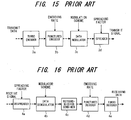
- Fig. 15 illustrates the structure of the signal modulator 1c on the transmitting side. Because the structure differs depending upon the communication scheme, this illustrates one example. Assume that the encoding rate and spreading factor of the modulation scheme are given as the modulation parameters.
- the transmit data is subjected to error correcting encoding by turbo encoding in a turbo encoder 3a. Here the encoding rate is assumed to be constant at all times.
- a punctured encoder 3b achieves the required encoding rate using a punctured code pattern.
- a data modulator 3c performs data modulation that is in accordance with the modulation scheme (number of multiple values). In general, the modulation scheme is QPSK, 16-QAM, 64-QAM, etc.
- a spreader 3d spreads the signal in accordance with the spreading factor. Spreading methods include a method of spreading along the time direction and a method of spreading along the frequency direction.
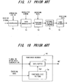
- Figs. 16 and 17 illustrate structures of the signal demodulator 2d on the receiving side, in which Fig. 16 illustrates a structure in which retransmission combining is performed before punctured decoding and Fig. 17 a structure in which retransmission combining is performed after punctured decoding. These correspond to Fig. 15.
- a despreader 4a despreads a receive signal in accordance with the spreading factor.
- a data demodulator 4b performs data demodulation that conforms to the modulation scheme. If a packet is a retransmission packet, a retransmission combiner 4c executes processing to combine the data of this packet with the data of the same packet received previously. As a result, a higher reception quality can be obtained.
- Retransmission combining is by (a) an arrangement (Fig. 16) in which combining is performed before punctured decoding and (b) an arrangement (Fig. 17) in which combining is performed after punctured decoding.
- the buffer structure, etc., in the two arrangements differs.
- a punctured decoder 4d performs punctured decoding that conforms to the encoding rate
- a turbo decoder 4e performs turbo decoding.
- Fig. 18 is a diagram showing the structure of the punctured decoder 4d. This diagram corresponds to Fig. 17.
- the punctured decoder 4d has a punctured code pattern generator 5a, which generates a punctured code pattern PCP conforming to the encoding rate, and a data buffer 5b.
- a signal RD obtained after data demodulation is stored in the data buffer 5b in an amount equivalent to the number of code "1"s in the punctured code pattern PCP.
- the punctured code pattern PCP differs depending upon the encoding rate and therefore the length of the buffer also differs.
- Fig. 19 illustrates an example of a buffer length of four (the number of "1"s in the punctured code pattern PCP is four).
- the stored signal RD is written to the positions of code "1"s in the punctured code pattern PCP, and a signal RD' obtained after punctured decoding is output.
- an additional modulation parameter is the number of multicodes in multicode transmission using a plurality of channels. However, a description of this is omitted.
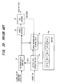
- Fig. 20 illustrates the structure of the receiving side from the retransmission combiner onward.
- a buffer 6a stores packets whose reception has failed along with the numbers of these packets.
- a buffer-data extraction unit 6b refers to a packet number and extracts the data of this packet, which is to be combined with a retransmitted packet, from the buffer 6a. If a receive packet (actually the signal obtained as a result of punctured decoding) is not a retransmission packet, i.e., if the receive packet is a new packet, the retransmission combiner 4c inputs the packet to a turbo decoder 4e. If the receive packet is a retransmission packet, then the retransmission combiner 4c combines the data of this packet with packet data read out of the buffer 6a and inputs the combined data to the turbo decoder 4e.
- a CRC checking unit 4f executes a CRC checking operation using the decoded data, checks to see whether the data contains an error, outputs the data as receive data and generates an ACK signal if no error is contained, and generates a NACK signal if the data contains an error. If the ACK signal is generated when a retransmission packet is received, a data/information storage unit 6c deletes this packet from the buffer 6a. If the NACK signal is received, the data/information storage unit 6c stores retransmission combination data in the buffer 6a together with the packet number.
- Fig. 21 illustrates an example of signal modulation on the transmitting side.
- the modulation scheme is 16-QAM (four multiple values) and that the encoding rate R is 3/4.
- a punctured code pattern PCP for the encoding rate 3/4 eight of the 18 bits will be code "1".
- Data B1 to B7 and B16 corresponding to the code "1"s of the punctured code pattern PCP become the data after punctured encoding and this data is output as C1 to C8. Since the 6-bit data becomes 8-bit data, the encoding rate is 3/4.
- 4-valued multivalue modulation is performed by 16-QAM and data E1, E2 is obtained. The data after such decoding is spread in dependence upon the spreading factor.
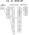
- Fig. 22 is an example of signal demodulation on the receiving side. Here the flow is opposite that of Fig. 21.
- punctured decoding data is written to the positions corresponding to the code "1"s of the punctured code pattern PCP.
- the original 6-bit data A1 to A6 is decoded by applying turbo decode processing to the data that prevails after punctured decoding.
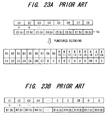
- Figs. 23A, 23B are diagrams for describing Chase combining, in which Fig. 23A is a diagram useful in describing Chase combining before punctured decoding and Fig. 23B a diagram useful in describing Chase combining after punctured decoding. The symbols are in accordance with the examples described above.
- data C1 to C8 that has undergone data demodulation is combined with data C1(b) to C8(b) in buffer 6a, as depicted in Fig. 23A.
- C1(b) to C8(b) represent combined values of previously transmitted data of a packet that is the same as the packet currently being received.
- the combined data is normalized in accordance with the number of retransmissions. That is, if a retransmission is a second retransmission, (i.e., two retransmissions following the initial transmission), the data in the buffer will be a combined value that is the result of two transmissions (the initial transmission + the first retransmission).
- the combined value obtained will be the result of three transmissions. This combined value, therefore, is divided by three.
- the 8-bit data obtained by retransmission and combination is substituted for the positions (B1 to B7, B16) which are the code "1"s in the punctured code pattern PCP (See Fig. 22), punctured decoding is applied and the results are input to the turbo decoder.
- Figs. 24A, 24B are diagrams for describing IR combining, in which Fig. 24A is a diagram useful in describing IR combining before punctured decoding and Fig. 24B a diagram useful in describing IR combining after punctured decoding.
- encoding is performed based upon a punctured code pattern that differs for every retransmission. Assume here that the number of patterns is two. In the case of two patterns, the pattern in the initial transmission and the pattern in the first retransmission differ from each other. In the second retransmission, a pattern that is identical with that of the initial transmission is used. Data combining is performed only in cases where an identical pattern is used.
- the data transmitted in the initial transmission and in retransmissions 2, 4, 6, ⁇ has undergone punctured encoding using the same pattern PCP [see (a) in Fig. 25], and therefore the data is combined with data that has been stored in a first buffer 6a-1 and the result is stored in the buffer 6a-1 again.
- the data transmitted in retransmissions 1, 3, 5, ⁇ has undergone punctured encoding using a punctured code pattern PCP' [see (b) in Fig. 25] different from the pattern PCP, and therefore the data is combined with data that has been stored in a second buffer 6a-2 and the result is stored in the buffer 6a-2 again.
- data D1 to D8 that has been decoded based upon the second pattern PCP' is combined with data [B8(b) to B11(b), B13(b), B14(b), B17(b), B18(b)] at the corresponding positions of the buffer 6a.
- Data that has thus undergone punctured decoding is subsequently input to the turbo decoder and subjected to turbo decoding.
- a packet for which reception has failed is retransmitted in an adaptive modulation scheme in which a signal is transmitted upon changing a modulation parameter in conformity with the conditions of the propagation path, a packet that has undergone signal modulation based upon a modulation parameter identical with that at the time of the initial transmission is transmitted.
- the reason for this is that packet data at the time of the initial transmission and packet data at the time of the retransmission must be combined on the receiving side. If the modulation parameter were to be changed, the data could not be combined because either the data lengths would differ or the punctured encoding patterns would differ.
- the conditions on the propagation path are constantly changing.
- the fluctuation can be as much as several tens of decibels when travel of the receiving station, shadowing and fading are taken into account.
- the scheduler may not always transmit a retransmission packet immediately. If multiple retransmissions are performed, a considerable length of time passes from the time of the initial packet transmission.
- the conditions of the propagation path at the time of the initial transmission and the conditions of the propagation path at the time of retransmission can differ, and it is conceivable that a modulation parameter set at the time of the initial transmission and that suited to the conditions of the propagation path at the time of retransmission will not match.
- an object of the present invention is to make possible transmission that matches the conditions of the propagation path even in a case where propagation path conditions at the time of initial transmission of a packet differ from those at the time of retransmission.
- Another object of the present invention is to so arrange it that retransmission signal combining can be carried out correctly on the side of the receiving station even if packet data is transmitted according to a modulation scheme conforming to currently prevailing propagation conditions in a case where propagation path conditions at the time of initial transmission of a packet differ from those at the time of retransmission.
- a further object of the present invention is to make it possible to prevent repeated packet reception failures, prevent excessive allocation of radio resources and utilize radio resources efficiently.
- the foregoing objects are attained by providing a packet receiving apparatus in a communication system for transmitting a packet signal upon changing over modulation parameters of a transmit signal in accordance with conditions of a propagation path, and, when the packet signal cannot be received correctly on a receiving side, retransmitting the packet signal, combining the packet data received previously and the retransmitted packet data and executing decode processing based upon the combined packet data.
- the packet receiving apparatus includes buffer means for storing receive packet data, which contains an error, with identifying information appended thereto; means for extracting packet data, which is to undergo retransmission combining, from the buffer upon referring to the identifying information of a retransmission packet; combining means for combining retransmission packet data with the packet data extracted from the buffer; decoding means for executing decode processing based upon the combined packet data; means for discriminating whether result of decoding is correct or erroneous.
- the packet receiving apparatus further includes means for comparing a first modulation parameter (e.g., number of multivalues in data modulation or encoding rate) that has been attached to a retransmission packet signal and a second modulation parameter that has been attached to packet data extracted from the buffer; and means for cutting out part of the packet data, which has been extracted from the buffer, and inputting it to the combining means if result of the comparison is that the conditions of the propagation path at the time of retransmission are inferior.
- a first modulation parameter e.g., number of multivalues in data modulation or encoding rate
- the packet receiving apparatus further includes means for comparing a first modulation parameter (e.g., number of multivalues in data modulation or encoding rate) that has been attached to a retransmission packet signal and a second modulation parameter that has been attached to packet data extracted from the buffer; and means for extracting data of a plurality of packets that are to undergo retransmission combining from the buffer and inputting these packets of data to the combining means if result of the comparison is that the conditions of the propagation path at the time of retransmission are superior.
- a first modulation parameter e.g., number of multivalues in data modulation or encoding rate
- the foregoing objects are attained by providing a packet transmitting apparatus in a communication system for transmitting a packet signal upon changing over modulation parameters of a transmit signal in accordance with conditions of a propagation path, and, when the packet signal cannot be received correctly on a receiving side, retransmitting the packet signal, combining the retransmitted packet data with the packet data received previously and executing decode processing based upon the combined packet data.
- the packet transmitting apparatus includes buffer means for storing a transmitted packet with identifying information and a modulation parameter appended thereto; means for deciding a modulation parameter based upon conditions of the propagation path; and retransmitting means for deleting a packet, for which successful reception has been sent back from a receiving side, from the buffer, and retransmitting a packet, for which reception failure has been sent back from the receiving side, upon attaching identifying information and a modulation parameter prevailing at time of retransmission, with the retransmission being performed based upon a modulation scheme that conforms to this modulation parameter.
- the packet transmitting apparatus further includes means for comparing a modulation parameter that has been attached to packet data to be retransmitted and a modulation parameter conforming to the conditions of the propagation path prevailing at the time of retransmission; and means for retransmitting a plurality of packets, which have been stored in the buffer, as a single retransmission packet signal upon attaching respective ones of identifying information of these packets if result of the comparison is that the conditions of the propagation path at the time of retransmission are superior to those that prevailed at the time of the previous transmission.
- the packet transmitting apparatus further includes means for comparing a modulation parameter that has been attached to packet data to be retransmitted and a modulation parameter conforming to the conditions of the propagation path prevail at the time of retransmission; and means for retransmitting part of a packet, which has been stored in the buffer, as a single retransmission packet signal upon attaching identifying information if result of the comparison is that the conditions of the propagation path at the time of retransmission are inferior to those that prevailed at the time of the previous transmission.
- the foregoing embodiments are such that even in a case where propagation path conditions at the initial transmission of a packet differ from those at the time of retransmission, a transmission that conforms to the current propagation conditions can be performed by changing the order in which packets are transmitted in such a manner that the modulation parameters will agree, or by changing the modulation parameter and then transmitting the signal.
- data corresponding to a retransmission packet can be extracted from a buffer and retransmission combining can be carried out, thereby making it possible to prevent repeated packet reception failures, prevent excessive allocation of radio resources and utilize radio resources efficiently.
- Fig. 1 is a block diagram of retransmission control implemented by a transmitting station in conformity with conditions of a propagation path according to the present invention.
- the dashed lines in Fig. 1 indicate the flow of data signals and the solid lines indicate the flow of control signals.
- Transmit data DT data that is actually transmitted via a network
- SBF signal buffer
- Implementations of the signal buffer include one in which retransmitted data and new data are kept separate from each other, one in which these items of data are kept together, and one in which these items of data are kept separate or kept together depending upon the type of traffic.
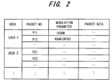
- the buffer stores, user by user, the modulation parameter (e.g., the type of data modulation scheme, namely QPSK, 16-QAM, ⁇ ) prevailing at the time of packet transmission and packet data in association with a packet number.
- the packet data is deleted from the buffer SBF if ACK information indicating successful reception is sent back from the receiving station. If NACK information indicating reception failure is sent back, the packet data is held in the buffer SBF and continues to be retained in the buffer until reception succeeds owing to retransmission.
- a scheduler 11 b selects the user whose packet is to be transmitted next and so notifies the transmit-data controller 11 a.
- the transmit-data controller 11 a transmits the transmit-signal data of this user, which is located in the signal buffer SBF, to a signal modulator 11c.
- an adaptive modulation controller 11 d calculates a modulation parameter suited to the user, reports the parameter to the signal modulator 11 c and inputs the modulation parameter to the transmit-data controller 11 a via a comparator 11f for comparing propagation path conditions.
- the signal modulator 11c modulates the packet signal (composed of the packet number, modulation parameter and packet data) using the reported modulation parameter and transmits the modulated signal wirelessly via a signal transmitting unit 11e. If ACK information indicating successful reception is sent back from the receiving station, the transmit-data controller 11 a deletes the corresponding packet data from the signal buffer SBF. If NACK information indicating reception failure is sent back from the receiving station, the transmit-data controller 11 a holds the modulation parameter and packet data in the signal buffer SBF in association with the packet number.
- the comparator 11f compares a propagation path condition (modulation parameter) B that prevailed when this packet was transmitted afresh and a propagation path condition (modulation parameter) C prevailing at the time of the present transmission. If B and C are the same, the comparator 11f sends the signal modulator 11c the modulation parameter of the initial transmission, the signal modulator 11c performs signal modulation using the reported modulation parameter and transmits the modulated signal wirelessly via the signal transmitting unit 11e. If B and C are different, however, any of the following three means can be adopted:
- the adaptive modulation controller 11 d inputs the modulation parameter conforming to the presently prevailing propagation path condition to the signal modulator 11 c, which proceeds to modulate and transmit the retransmission packet based upon the modulation parameter that has entered from the adaptive modulation controller 11 d.
- Fig. 3 is a block diagram illustrating the structure on the receiving side from a retransmission combiner onward.
- a buffer data / information extraction unit 22 has a packet-number comparator 22a for referring to the packet number of a packet that has been retransmitted, extracting the packet data having this packet number from the buffer 21 and inputting the data to a packet data unit 22b.
- the extraction unit 22 also inputs the modulation parameter of this packet of data to a modulation parameter comparator 22c.
- the modulation parameter comparator 22c compares the modulation parameter of the retransmission packet and the modulation parameter that has entered from the buffer 21 and inputs the result of the comparison to the packet data unit 22b. On the basis of the result of the comparison of modulation parameters, the packet data unit 22b either inputs the packet data that has entered from the buffer 21 to a retransmission combiner 23 as is or upon separating the data. If a receive packet (actually a signal obtained after application of punctured decoding) is not a retransmission packet, i.e., if the receive packet is a new packet, the retransmission combiner 23 allows the packet to pass as is and inputs it to a turbo decoder 24. If the packet of data is retransmission packet data, then the retransmission combiner 23 combines it with the packet of data that enters from the packet data unit 22b and inputs the combined data to the turbo decoder 24.
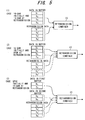
- Fig. 5 is a diagram for describing retransmission combining. Assume that modulation has been performed according to a modulation parameter (data modulation scheme) of 16-QAM both at the time of initial transmission and at the time of retransmission, as indicated at (1) in Fig. 5. In such case the data is modulated and transmitted four bits (b1 to b4; b1' to b4') at a time both at the time of initial transmission and at the time of retransmission. The packet-data lengths, therefore, are equal. For the sake of explanation, assume that the packet-data length is four bits.
- the packet data unit 22b inputs all of the packet data (b1 to b4) that enters from the buffer 21 to the retransmission combiner 23, and the latter combines the retransmission data (b1' to b4') and the packet data (b1 to b4), which has been read out of the buffer, and outputs the combined data.
- modulation has been performed by 16-QAM at the time of the initial transmission and by QPSK (4-QAM) at the time of the retransmission, as indicated at (2) in Fig. 5.
- the data is modulated and transmitted four bits (b1 to b4) at a time at the time of the initial transmission and is modulated and transmitted two bits (b1' and b2'; b3' and b4') at a time at the time of retransmission.
- the packet-data length therefore, is half that which prevailed at the time of the initial transmission. In other words, the packet-data length within the buffer is double the packet length prevailing at the time of retransmission.
- the packet data unit 22b inputs the first half (b1 and b2) of the packet data (b1 to b4) that enters from the buffer 21 to the retransmission combiner 23, and the retransmission combiner 23 combines the retransmission data (b1' and b2') and the packet data (b1 and b2) and outputs the combined data.
- the packet data unit 22b similarly inputs the latter half (b3 and b4) of the packet data (b1 to b4) that enters from the buffer 21 to the retransmission combiner 23, and the retransmission combiner 23 combines the retransmission data (b3' and b4') and the packet data (b3 and b4) and outputs the combined data.
- the data is modulated and transmitted two bits (b1 and b2; b3 and b4) at a time at the time of the initial transmission and is modulated and transmitted four bits (b1' to b4') at a time at the time of retransmission.
- the packet-data length therefore, is double that which prevailed at the time of the initial transmission.
- the packet data unit 22b since the packet data (b1 and b2) enters from the buffer 21, the packet data unit 22b first inputs this packet data to the retransmission combiner 23, which proceeds to combine the first half (b1' and b2') of the retransmission data (b1' to b4') and the packet data (b1 and b2) and output the combined data. Then, since the packet data (b3 and b4) enters from the buffer 21 next, the packet data unit 22b inputs this packet data to the retransmission combiner 23, which proceeds to combine the latter half (b3' and b4') of the retransmission data (b1' to b4') and the packet data (b3 and b4) and output the combined data.
- the turbo decoder 24 applies turbo decoding to the input data, and a CRC checking unit 25 executes a CRC checking operation using the decoded data, checks to see whether the data contains an error, outputs the data as receive data and generates an ACK signal if no error is contained, and generates a NACK signal if the data contains an error. If the ACK signal is generated when a retransmission packet is received, a data/information storage unit 26 deletes this packet from the buffer 21. If the NACK signal is received, the data/information storage unit 26 stores retransmission combination data in the buffer 21 together with the packet number. A transmitting unit 27 transmits the ACK/NACK information to the transmitting side.
- the present invention is such that the packet number of a packet that has been transmitted is compared with the packet number of a packet that has been stored in the buffer 21, as a result of which packet data corresponding to a retransmitted packet can be read out of the buffer 21 and combined even though the order of packet transmission is switched. Further, modulation parameters are compared. If the modulation parameters are found to differ, the data length of a retransmission packet and the data length of a packet within the buffer are calculated, thereby making it possible to extract from the buffer and combine data that corresponds to the data of the retransmitted packet.
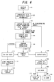
- Fig. 6 is a flowchart illustrating retransmission combining processing according to the present invention.
- a transmitter and receiver usually possess identical buffers and the buffers are controlled using identical ACK/NACK information.
- Data in a new transmit packet is stored at the tail-end of the buffer [BF(4) in Fig. 4) after transmission (after reception).
- the packet at BF(0) is transmitted and, after transmission, it is stored at BF(4) again while being shifted.
- the retransmission data and the packet of data at BF(0) are combined and, if reception fails, the combined data is stored at BF(4) while being shifted.
- the content of each buffer is shifted one at a time [BF(i) (BF(i+1)] whenever transmission/reception is performed.
- the initial propagation path conditions and the present propagation path conditions are similar for the packet that is within the buffer, then transmitting this packet makes more efficient retransmission possible. If propagation path conditions equivalent to those at the time of the initial transmission prevail, there is a possibility that reception will fail but an improvement in reception quality by virtue of combining data can be expected. To what degree propagation path conditions can be allowed is also decided by the degree of improvement in reception quality achieved by combining data. At the receiver, however, retransmission of the packet based upon buffer BF(0) is expected; if another packet is transmitted, the combining of data cannot be carried out.
- the signal demodulator on the receiving side is provided with the buffer data / information extraction unit 22.
- the signal demodulator on the receiving side receives a transmitted packet (step 101), demodulates the data, extracts packet information (step 102) and inputs the packet number and modulation parameter to the buffer data / information extraction unit 22.
- the buffer data / information extraction unit 22 compares the packet number of the entered packet with the packet numbers of packet data in the buffer (step 103). If there is no identical packet, then the entered packet is judged to be a new transmit packet and the data is not sent to the retransmission combiner 23. Accordingly, if the entered packet is a new transmit packet, the retransmission combiner 23 outputs the data without performing retransmission combining (step 104).
- the packet data having this number is extracted from the buffer 21 and is stored in the packet data unit 22b of the buffer data / information extraction unit 22 (step 105).
- the buffer data / information extraction unit 22 compares the modulation parameter that has been attached to the retransmission packet and the modulation parameter of the packet data that has been read out of the buffer 21 (step 106).
- the buffer data / information extraction unit 22 sends the packet data that has been read out to the packet data unit 22b to the retransmission combiner 23, which performs retransmission combining (step 107) and outputs the combined data (step 104).
- the buffer data / information extraction unit 22 sends the packet data that has been read out to the packet data unit 22b to the retransmission combiner 23, which performs retransmission combining (step 107) and outputs the combined data (step 104).
- the packet data obtained by combining is output to the turbo decoder 24 and is stored temporarily in a memory 26a in the data/information storage unit 26 (step 108).
- the turbo decoder 24 averages (normalizes) the entered combined data based upon the number of retransmissions, applies turbo decode processing to the averaged packet data and inputs the decoded result to the CRC checking unit 25.
- the CRC checking unit (the packet discriminator on the receiving side) 25 performs a CRC check and outputs ACK/NACK based upon the result of the CRC check (step 109). If it is sent ACK information, the data/information storage unit 26 discards the packet data that has been saved.
- the data/information storage unit 26 stores the packet data that is being held at the tail end [BF(4) in Fig. 4] of buffer 21. A similar operation is performed by the transmitter. As shown in Fig. 4, packet number, modulation parameter of the packet, number of retransmissions and data have been stored in the buffer 21. In this case, the number of retransmissions is counted up by one count.
- the modulation parameter is diminished to alter the setting and the packet is transmitted.
- the modulation parameter the number of multiple values in data modulation is reduced, the number of multicodes is reduced, the spreading factor is raised or the encoding rate is reduced.
- the number of items of data that can be transmitted at the time of retransmission is made less than that at the time of the initial transmission. It should be noted that a plurality of modulation parameters can be changed simultaneously to reduce the number of items of transmit data.
- retransmission that conforms to the propagation path conditions is carried out by lowering the modulation parameter (i.e., by reducing the amount of transmit information per packet).
- the data length in the initial packet transmission i.e., the packet data in the buffer
- the data length of the retransmission packet at the time of retransmission are calculated by referring to each modulation parameter. In this case, the data length of the retransmission packet is shortened [see (2) in Fig. 5].
- the buffer data / information extraction unit 22 cuts part of the data having the length corresponding to the data length of the present retransmission packet from the packet data that has been read out to the packet data unit 22b from the buffer 21 (step 112) and sends only the data that has been cut out to the retransmission combiner 23.
- the latter combines the cut-out data and the present retransmission data (step 107), outputs the combined data and stores the combined data in the memory 26a of the data/information storage unit 26 (steps 107, 104, 108).
- the buffer data / information extraction unit 22 stores the remaining data not used in combining in the memory 26a of the data/information storage unit 26 together with the packet number, modulation parameter and number of retransmissions (step 113).
- the data/information storage unit 26 discards the data segment having the length corresponding to the present retransmission packet that has been stored in the internal memory 26a (step 110) and writes only the data not used in retransmission combining to the buffer 21 again (step 114). In relation to this portion of the data, retransmission combining is not carried out and therefore the number of retransmissions is not incremented. If NACK is reported with regard to the present retransmission packet, both items of data are stored together in an area of the same buffer 21 (steps 111, 114). In this case, the number of retransmissions (number of combining operations) differs between the two items of data. The two items of data can also be stored in different buffer areas.
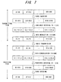
- Fig. 7 illustrates an example of packet structure at the time of the initial transmission.
- the symbols correspond to those in Fig. 21.
- the transmit data is A1 to A60 at the time of the initial transmission in Fig. 7.
- the transmit data A1 to A60 is separated into sets of 6-bit data A1 to A6, A7 to A12, ⁇ , and A55 to A60.
- Each set of 6-bit data is turbo encoded at an encoding rate of 1/3 to obtain B1 to B18, B19 to B36, ⁇ , B163 to B180.
- Each 18-bit turbo code is subjected to punctured encoding at an encoding rate of 3/4 to thereby obtain sets of 8-bit data C1#1 to C1#8, C2#1 to C2#8, ⁇ , C10#1 to C10#8. If the 8-bit data C1#1 to C1#8, C2#1 to C2#8, ⁇ , C10#1 to C10#8 is subjected to data modulation by 16-QAM owing to the conditions of the propagation path, then the data is converted to 4-bit data E1 to E20, data modulation by 16-QAM is applied and the modulated data is transmitted.
- C1#1 to C1#8, ⁇ , C10#1 to C10#8 is obtained by data demodulation according to 16-QAM.
- Each item of data is written to a "1" portion of a punctured code pattern B1 to B180 by punctured decoding.
- the buffer data / information extraction unit 22 inputs all "0"s to the retransmission combiner 23.
- the latter combines all "0"s with the new packet data B1 to B180, inputs the result of combining to the turbo decoder 24 and stores the result in the memory 26a of the data/information storage unit 26.
- the turbo decoder 24 subjects the new packet data to turbo decoding to obtain data A1 to A60. If the data A1 to A60 is found to be erroneous by a CRC check, the data/information storage unit 26 plants the packet data B1 to B180, which has been stored in memory 26a, in the buffer 21.
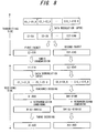
- Fig. 8 illustrates packet structure in a case where packet data is retransmitted upon changing the modulation scheme from 16-QAM to QPSK by reason of a deterioration in propagation path conditions at the time of retransmission. If the sets of 8-bit data C1#1 to C1#8, C2#1 to C2#8, ⁇ , C10#1 to C10#8 after application of punctured encoding are subjected to data modulation by QPSK modulation, the data is converted to 2-bit data E1 to E40, modulated according to QPSK and transmitted.
- the data E1 to E40 is twice the number of data in comparison with the initial transmission.
- the transmitter therefore transmits the data upon splitting it into two packets.
- the first packet will be described.
- the data E1 to E20 is transmitted by the first packet, and C1#1 to C1#8, ⁇ , C5#1 to C5#8 is obtained by QPSK data demodulation.
- Each item of data is written to a "1" portion of a punctured code pattern B1 to B90 by punctured decoding.
- Data at B1 (b) to B180(b) is read out of the buffer 21 and stored in the packet data unit 22b of the buffer data / information extraction unit 22.
- the buffer data / information extraction unit 22 cuts out the first half B1 (b) to B90(b) and inputs it to the retransmission combiner 23, and also stores the latter half B91 (b) to B180(b) in the memory 26a of the data/information storage unit 26.
- the retransmission combiner 23 combines the cut-out first half B1 (b) to B90(b) of the packet and the retransmission packet data B1 to B90, inputs the combined data to the turbo decoder 24 and stores it in the memory 26a of the data/information storage unit 26.
- the turbo decoder 24 averages the combined packet data based upon the number of retransmissions, applies turbo decoding to the averaged packet data and obtained A1 to A30. If it is clarified by a CRC check that the data A1 to A30 is not erroneous, the data/information storage unit 26 stores only the remaining data B91 (b) to B180(b) in the buffer 21. If the data A1 to A30 is erroneous, however, then the data/information storage unit 26 stores the data obtained by combining the first half in the buffer 21 again and increments the retransmission count. Further, the data/information storage unit 26 stores the latter half in the buffer 21 as is.
- the modulation parameter is changed to a larger setting and that the packet is then retransmitted.
- the number of multiple values in modulation is increased, the number of multicodes is increased, the spreading factor is lowered or the encoding rate is made to approach unity.
- the number of items of data that can be transmitted at the time of retransmission is made greater than that at the time of the initial transmission and throughput can be improved.
- Data length (packet length) is enlarged by setting the parameter to be higher than at the time of the initial transmission.
- the transmitting station can add data of another packet onto the packet data that prevailed at the initial transmission and can retransmit the data.
- the packet number of the packet of data that has been added on is appended in addition to the packet number of the retransmission packet at the time of initial transmission.
- the buffer data / information extraction unit 22 on the receiving side recognizes by means of the packet-number comparator 22a whether the data of the packets having the packet number of the retransmission packet and the packet number of the added-on data is present in the buffer 21.
- the buffer data / information extraction unit 22 judges the additional data to be new data, extracts only the data in buffer area BF(0) and sends this data to the retransmission combiner 23 again. Since all of the data of buffer area BF(0) is retransmitted, this data is input to the retransmission combiner 23 as is. The latter combines the retransmission packet data corresponding to the first packet number and the data in buffer area BF(0).
- the data that has been added on is judged to be retransmission of the packet corresponding to the data in buffer area BF(1).
- the data of BF(1) also is extracted simultaneously and stored in the packet data unit 22b.
- all of the data in buffer area BF(1) is not necessarily retransmitted.
- the modulation parameter of the retransmission data has been altered and cases where the parameter is the same and only the number of items of data has been reduced.
- the buffer data / information extraction unit 22 identifies the modulation parameter and data length using the modulation parameter comparator 22c, cuts out the portion of the data corresponding to the length of data that has been transmitted from the data of buffer area BF(1) in the packet data unit 22b and sends the cut-out data to retransmission combiner 23. After the retransmission combiner 23 combines the data in accordance with the numbers of retransmissions of both items of data [the numbers of retransmissions that have been recorded in BF(0) and BF(1)], normalization is carried out. These items of data are stored temporarily in memory 26a of the data/information storage unit 26.
- the CRC checking unit 25 performs a CRC check and reports ACK/NACK regarding both items of data (in this case the data corresponding to the first packet number and the data corresponding to the second packet number).
- the data/information storage unit 26 stores data in or discards data from the buffer 21 depending upon each ACK/NACK reported. If NACK is reported for both items of data, then these items of data are stored in separate buffer areas.
- Fig. 9 illustrates an example of packet structure at the time of the initial transmission.
- the transmit data is A1 to A60 at the time of the initial transmission in Fig. 9.
- the transmit data A1 to A60 is separated into sets of 6-bit data A1 to A6, A7 to A12, ⁇ , A55 to A60.
- Each set of 6-bit data is turbo encoded at an encoding rate of 1/3 to obtain B1 to B18, B19 to B36, ⁇ , B163 to B180.
- Each 18-bit turbo code is subjected to punctured encoding at an encoding rate of 3/4 to thereby obtain sets of 8-bit data C1#1 to C1#8, C2#1 to C2#8, ⁇ , C10#1 to C10#8.
- the first packet will be described.
- the data E1 to E20 is transmitted by the first packet, and C1#1 to C1#8, ⁇ , C5#1 to C5#8 is obtained by QPSK data demodulation.
- Each item of data is written to a "1" portion of a punctured code pattern B1 to B90 by punctured decoding.
- the buffer data / information extraction unit 22 inputs all "0"s to the retransmission combiner 23.
- the latter combines all "0"s with the new packet data B1 to B90, inputs the result of combining to the turbo decoder 24 and stores the result in the memory 26a of the data/information storage unit 26.
- the turbo decoder 24 subjects the new packet data to turbo decoding to obtain data A1 to A30. If the data A1 to A30 is found to be erroneous by a CRC check, the data/information storage unit 26 plants the packet data B1 to B90, which has been stored in memory 26a, in the buffer 21.
- the turbo decoder 24 applies turbo decoding to the new packet data to obtain data A1 to A30. If it is determined by the CRC check that the data A1 to A30 is erroneous, the data/information storage unit 26 plants the packet data B1 to B90 that has been stored in the memory 26a to the buffer 21.
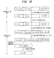
- Figs. 10 and 11 are diagrams of packet structure in a case where packet data is retransmitted upon changing the modulation scheme from QPSK to 16-QAM by reason of an improvement in propagation path conditions at the time of retransmission.
- the sets of 8-bit data C1#1 to C1#8, C2#1 to C2#8, ⁇ , C10#1 to C10#8 resulting from punctured encoding is modulated according to 16-QAM.
- the data is converted to 4-bit data E1 to E20, data modulation by 16-QAM is applied and the modulated data is transmitted. Since the data rate of 16-QAM is twice that at the time of the initial transmission, the transmitter combines the first and second packets of the initial transmission into one packet and transmits this packet.
- the demodulator on the receiving side receives the data E1 to E20, applies 16-QAM modulation to generate decoded data C1#1 to C1#8, C2#1 to C2#8, ⁇ , C10#1 to C10#8, and the punctured decoder writes this decoded data to "1" portions of a punctured code pattern B1 to B180 to perform punctured decoding.
- the buffer data / information extraction unit 22 first inputs the data B1(b) to B90(b) to the retransmission combiner 23.
- the latter combines the data B1(b) to B90(b) with the first half B1 to B90 of the retransmission packet data B1 to B180, inputs the combined data to the turbo decoder 24 and stores the combined data in the memory 26a of the data/information storage unit 26.
- the turbo decoder 24 applies turbo decoding to packet data obtained as a result of averaging the combined packet data based upon the number of retransmissions and obtains data A1 to A30. If the data A1 to A30 is found to be erroneous by a CRC check, the data/information storage unit 26 stores the combined data in the buffer 21 again and increments the number of retransmissions.
- the buffer data / information extraction unit 22 inputs the data of B91 (b) to B180(b) from the packet data unit 22b to the retransmission combiner 23.
- the latter combines the data of B91 (b) to B180(b) with the latter half B91 to B180 of the retransmission packet data B1 to B180 (see Fig. 11), inputs the combined data to the turbo decoder 24 and stores the combined data in the memory 26a of the data/information storage unit 26.
- the turbo decoder 24 applies turbo decoding to packet data obtained as a result of averaging the combined packet data based upon the number of retransmissions and obtains data A31 to A60. If the data A31 to A60 is found to be erroneous by a CRC check, the data/information storage unit 26 stores the combined data in the buffer 21 again and increments the number of retransmissions.
- the foregoing relates to a case where the data modulation scheme is changed over as a modulation parameter in accordance with the conditions of the propagation path.
- the encoding rate R can also be changed over in accordance with the propagation path conditions. For example, the more the conditions of the propagation path worsen, the more the encoding rate R is lowered to strengthen resistance against the influence of the propagation path. As a result, the encoding rate at the time of retransmission changes from that which prevailed at the time of the initial transmission.
- the punctured code pattern used in punctured encoding will differ. This means that retransmission combining cannot be performed at a stage prior to punctured decoding. That is, simple combining of data at identical positions can no longer be performed, as in Chase combining. If the modulation parameter comparator 22c in Fig. 2 has determined that the encoding rate is different, packet data corresponding to data of a retransmission packet is read out of the buffer 21 and sent to the retransmission combiner 23. Since the data-write position of packet data in the buffer 21 and of the data prevailing after the punctured decoding of the retransmission packet differ, combining is carried out taking into consideration each of the punctured code patterns.
- Fig. 12 is a diagram useful in describing combining in a case where encoding rate differs. This corresponds to the packet structure in Fig. 7 at the time of the initial transmission.
- the encoding rate R is 3/4 and data is transmitted upon applying 16-QAM data modulation.
- the data stored in the buffer 21 that stores packets for which reception has failed is data B1 to B180 that prevails following punctured decoding, which data is obtained by subjecting 80-bit demodulated data to decoding according to a punctured code pattern that conforms to the encoding rate R of 3/4.
- the data after modulation is E1 to E30, which is split into two packets.
- the packets are E1 to E20 and E21 to E30, though this can be decided at will.
- the receiver After the data is demodulated, the receiver performs punctured decoding using a punctured code pattern that conforms to the encoding rate of 1/2. After punctured decoding, the receiver cuts data B1(b) to B120(b) corresponding to B1 to B120 out of the initially transmitted packet from the buffer 21 and performs combining using the retransmission combiner 23. Operation after retransmission combining (turbo decoding, CRC check and buffering conforming to the results of the check) is the same as that in the case where the data modulation scheme is changed over.
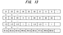
- Fig. 13 illustrates an example of retransmission combining by the retransmission combiner 23.
- Data is written to the positions of C1 to C8 in case of an encoding rate R of 3/4, and data is written to the positions of D1 to D4 in case of an encoding rate R of 1/2.
- the code "1"s of both patterns overlap when retransmission combining is carried out, the value after combining is halved and the result of combining is output.
- the result of combining is output as. This is followed by performing turbo decoding, CRC check and a buffering operation conforming to the results of the check.
- a punctured decoder applies punctured decode processing to a retransmission packet signal;
- the modulation parameter comparator 22c compares the encoding rate that has been attached to the retransmission packet signal with the encoding rate that has been attached to packet data extracted from the buffer 21; 3. if the result of the comparison is that the conditions of the propagation path at the time of retransmission are poor, part of the packet data that has been extracted from the buffer 21 is cut out and input to the retransmission combiner 23; and 4. the retransmission combiner 23 combines the packet data prevailing after punctured decoding with the packet data cut out from the buffer 21.
- the retransmission combiner 23 combines a plurality of parts of the retransmission packet data prevailing after punctured decoding with corresponding ones of the plurality of packets of data that have been extracted from the buffer 21 and outputs the combined data.
- the present invention is such that even in a case where propagation path conditions at the initial transmission of a packet differ from those at the time of retransmission, a transmission that conforms to the currently prevailing propagation conditions can be performed by changing the order in which packets are transmitted in such a manner that the modulation parameters will agree, or by changing the modulation parameter and then transmitting the signal. Further, by comparing packet numbers and comparing modulation parameter on the receiving side, data corresponding to a retransmission packet can be extracted from a buffer and retransmission combining can be carried out, thereby making it possible to prevent repeated packet reception failures, prevent excessive allocation of radio resources and utilize radio resources efficiently.
- the side of the receiving station is provided with a function for comparing packet numbers and a function for comparing modulation parameters, appropriate data is extracted from the buffer and the data can be combined. Therefore, even in a case where propagation path conditions at the time of initial transmission of a packet and the propagation path conditions at the time of retransmission differ, packet transmission and reception conforming to the propagation path conditions at the time of retransmission can be performed and it is possible to prevent repeated packet reception failures. Alternatively, it is possible to prevent use of excessive radio resources.
Landscapes
- Engineering & Computer Science (AREA)
- Computer Networks & Wireless Communication (AREA)
- Signal Processing (AREA)
- Quality & Reliability (AREA)
- Detection And Prevention Of Errors In Transmission (AREA)
- Mobile Radio Communication Systems (AREA)
- Data Exchanges In Wide-Area Networks (AREA)
- Communication Control (AREA)
Applications Claiming Priority (2)
| Application Number | Priority Date | Filing Date | Title |
|---|---|---|---|
| JP2003194823 | 2003-07-10 | ||
| JP2003194823A JP2005033399A (ja) | 2003-07-10 | 2003-07-10 | パケット送受信装置 |
Publications (2)
| Publication Number | Publication Date |
|---|---|
| EP1496638A2 true EP1496638A2 (fr) | 2005-01-12 |
| EP1496638A3 EP1496638A3 (fr) | 2006-06-07 |
Family
ID=33448010
Family Applications (1)
| Application Number | Title | Priority Date | Filing Date |
|---|---|---|---|
| EP20040007776 Withdrawn EP1496638A3 (fr) | 2003-07-10 | 2004-03-31 | Emetteur-récepteur par paquets avec demandes de retransmission et modulation adaptatif |
Country Status (4)
| Country | Link |
|---|---|
| US (1) | US20050008026A1 (fr) |
| EP (1) | EP1496638A3 (fr) |
| JP (1) | JP2005033399A (fr) |
| CN (2) | CN101052007A (fr) |
Cited By (9)
| Publication number | Priority date | Publication date | Assignee | Title |
|---|---|---|---|---|
| WO2006098550A1 (fr) * | 2005-02-04 | 2006-09-21 | Lg Electronics Inc. | Procede de transmission et de reception de paquets dans un systeme de communication mobile |
| EP2023520A1 (fr) * | 2007-08-07 | 2009-02-11 | Nokia Siemens Networks Oy | Dispositif et procédé pour transmission de paquets de données |
| WO2009075899A1 (fr) * | 2007-12-13 | 2009-06-18 | Qualcomm Incorporated | Combinaison harq à blocs de codage pour des systèmes à accès multiples par répartition orthogonale de la fréquence |
| CN101686311A (zh) * | 2005-10-11 | 2010-03-31 | 三星电子株式会社 | 数字广播发送和接收系统及其信号处理方法 |
| US7839812B2 (en) | 2005-02-04 | 2010-11-23 | Lg Electronics Inc. | Method for transmitting and receiving packet in mobile communication system |
| GB2480116A (en) * | 2010-05-04 | 2011-11-09 | Lantiq Deutschland Gmbh | System which completes buffered ARQ retransmissions before implementing adaption of communication parameters and detects adaption failure |
| US8619876B2 (en) | 2005-10-11 | 2013-12-31 | Samsung Electronics Co., Ltd. | Method for turbo transmission of digital broadcasting transport stream, a digital broadcasting transmission and reception system, and a signal processing method thereof |
| US8661307B2 (en) | 2009-01-15 | 2014-02-25 | Fujitsu Limited | Transmitter device, communication system, and communication method |
| WO2018143857A1 (fr) * | 2017-02-06 | 2018-08-09 | Telefonaktiebolaget Lm Ericsson (Publ) | Améliorations d'une retransmission due à des transmissions conflictuelles pour différents services |
Families Citing this family (22)
| Publication number | Priority date | Publication date | Assignee | Title |
|---|---|---|---|---|
| FI20045244A0 (fi) * | 2004-06-28 | 2004-06-28 | Nokia Corp | Lähetystehon ohjaus |
| US9385843B2 (en) * | 2004-12-22 | 2016-07-05 | Qualcomm Incorporated | Method and apparatus for using multiple modulation schemes for a single packet |
| CN101142765A (zh) | 2005-03-23 | 2008-03-12 | 富士通株式会社 | 移动通信系统 |
| WO2006123471A1 (fr) * | 2005-05-16 | 2006-11-23 | Sharp Kabushiki Kaisha | Dispositif de communication radio et méthode de communication radio |
| JP4649329B2 (ja) * | 2005-12-28 | 2011-03-09 | 富士通株式会社 | 移動端末装置及び同装置におけるチャネル補償方法 |
| JP2008053854A (ja) * | 2006-08-22 | 2008-03-06 | Fujitsu Ltd | データの再送方法、通信装置、およびコンピュータプログラム |
| JP4885971B2 (ja) * | 2006-09-29 | 2012-02-29 | 富士通株式会社 | 基地局装置 |
| US7865610B2 (en) * | 2007-03-12 | 2011-01-04 | Nautel Limited | Point to multipoint reliable protocol for synchronous streaming data in a lossy IP network |
| US8379738B2 (en) | 2007-03-16 | 2013-02-19 | Samsung Electronics Co., Ltd. | Methods and apparatus to improve performance and enable fast decoding of transmissions with multiple code blocks |
| US8161342B2 (en) * | 2007-12-13 | 2012-04-17 | Qualcomm Incorporated | Forward and reverse shifting selective HARQ combining scheme for OFDMA systems |
| JP5063387B2 (ja) | 2008-01-28 | 2012-10-31 | 京セラ株式会社 | 無線通信システム、送信装置、受信装置、無線通信方法 |
| JP2009182780A (ja) * | 2008-01-31 | 2009-08-13 | Nec Corp | 再送プロセスのデータ処理方法およびそれを用いた通信装置 |
| DE112010004553T5 (de) * | 2009-11-24 | 2012-09-06 | Electronics And Telecommunications Research Institute | Verfahren zum Senden eines Rahmens in einem Drahtloskommunikationssystem auf Mehrbenutzerbasis |
| CN101854298A (zh) * | 2010-05-19 | 2010-10-06 | 中国农业银行股份有限公司 | 报文的自动链接方法、账务修正方法及系统 |
| JP2011160455A (ja) * | 2011-03-24 | 2011-08-18 | Fujitsu Ltd | 移動通信システム |
| WO2012162877A1 (fr) * | 2011-05-30 | 2012-12-06 | Renesas Mobile Corporation | Procédé, appareil et élément de réseau pour une configuration tdd dynamique |
| WO2013021442A1 (fr) * | 2011-08-05 | 2013-02-14 | 富士通株式会社 | Circuit de transmission, circuit de réception, système de transmission/réception, procédé de commande de système de transmission/réception |
| WO2015072905A1 (fr) * | 2013-11-12 | 2015-05-21 | Telefonaktiebolaget L M Ericsson (Publ) | Dispositifs et procédés de gestion de (re)transmissions aveugles dans un réseau |
| WO2015178415A1 (fr) * | 2014-05-21 | 2015-11-26 | 日本電気株式会社 | Appareil de communication, appareil de commande, système de communication et procédé de commande de transmission |
| JP2019169753A (ja) * | 2016-08-12 | 2019-10-03 | 株式会社Nttドコモ | ユーザ装置及び信号送信方法 |
| US12598031B2 (en) | 2020-06-12 | 2026-04-07 | Sony Group Corporation | Communication devices and methods |
| CN114978104B (zh) * | 2021-02-18 | 2025-04-08 | 北京京东方光电科技有限公司 | 数据互斥滤波电路及数据互斥滤波方法 |
Family Cites Families (13)
| Publication number | Priority date | Publication date | Assignee | Title |
|---|---|---|---|---|
| US6338090B1 (en) * | 1998-03-27 | 2002-01-08 | International Business Machines Corporation | Method and apparatus for selectively using input/output buffers as a retransmit vehicle in an information handling system |
| US6359877B1 (en) * | 1998-07-21 | 2002-03-19 | Telefonaktiebolaget Lm Ericsson (Publ) | Method and apparatus for minimizing overhead in a communication system |
| US6507582B1 (en) * | 1999-05-27 | 2003-01-14 | Qualcomm Incorporated | Radio link protocol enhancements for dynamic capacity wireless data channels |
| US6629285B1 (en) * | 2000-01-04 | 2003-09-30 | Nokia Corporation | Data transmission |
| JP2001326657A (ja) * | 2000-05-17 | 2001-11-22 | Canon Inc | ノード装置、ネットワークおよびネットワーク伝送制御方法 |
| US7346037B2 (en) * | 2001-03-26 | 2008-03-18 | Lg Electronics Inc. | Method of transmitting or receiving a data packet in packet data communication system using hybrid automatic repeat request |
| US7289567B2 (en) * | 2001-04-30 | 2007-10-30 | Motorola, Inc. | Apparatus and method for transmitting and receiving data using partial chase combining |
| KR100539864B1 (ko) * | 2001-07-25 | 2005-12-28 | 삼성전자주식회사 | 부호분할다중접속 이동통신시스템에서 고속 데이터의 재전송장치 및 방법 |
| SE0103506D0 (sv) * | 2001-10-19 | 2001-10-19 | Ericsson Telefon Ab L M | HARQ stall avoidance |
| KR100827147B1 (ko) * | 2001-10-19 | 2008-05-02 | 삼성전자주식회사 | 부호분할다중접속 이동통신시스템에서 고속 데이터의효율적 재전송 및 복호화를 위한 송,수신장치 및 방법 |
| KR100557167B1 (ko) * | 2001-11-02 | 2006-03-03 | 삼성전자주식회사 | 이동통신시스템에서의 재전송 장치 및 방법 |
| US7212532B1 (en) * | 2001-12-21 | 2007-05-01 | Rockwell Collins, Inc. | Message re-sending protocol for a wireless communications system |
| KR100460970B1 (ko) * | 2002-01-10 | 2004-12-09 | 삼성전자주식회사 | 데이터 송수신 시스템 및 방법 |
-
2003
- 2003-07-10 JP JP2003194823A patent/JP2005033399A/ja active Pending
-
2004
- 2004-03-25 US US10/808,811 patent/US20050008026A1/en not_active Abandoned
- 2004-03-31 EP EP20040007776 patent/EP1496638A3/fr not_active Withdrawn
- 2004-05-28 CN CNA2007101046534A patent/CN101052007A/zh active Pending
- 2004-05-28 CN CN2004100455535A patent/CN100407691C/zh not_active Expired - Fee Related
Cited By (20)
| Publication number | Priority date | Publication date | Assignee | Title |
|---|---|---|---|---|
| US7839812B2 (en) | 2005-02-04 | 2010-11-23 | Lg Electronics Inc. | Method for transmitting and receiving packet in mobile communication system |
| WO2006098550A1 (fr) * | 2005-02-04 | 2006-09-21 | Lg Electronics Inc. | Procede de transmission et de reception de paquets dans un systeme de communication mobile |
| CN101112033B (zh) * | 2005-02-04 | 2011-08-31 | Lg电子株式会社 | 在移动通信系统中发送和接收分组的方法 |
| CN101686311B (zh) * | 2005-10-11 | 2013-05-01 | 三星电子株式会社 | 数字广播发送和接收系统及其信号处理方法 |
| US8867623B2 (en) | 2005-10-11 | 2014-10-21 | Samsung Electronics Co., Ltd. | Method for turbo transmission of digital broadcasting transport stream, a digital broadcasting transmission and reception system, and a signal processing method thereof |
| CN101686311A (zh) * | 2005-10-11 | 2010-03-31 | 三星电子株式会社 | 数字广播发送和接收系统及其信号处理方法 |
| US8804841B2 (en) | 2005-10-11 | 2014-08-12 | Samsung Electronics Co., Ltd. | Method for turbo transmission of digital broadcasting transport stream, a digital broadcasting transmission and reception system, and a signal processing method thereof |
| US8619876B2 (en) | 2005-10-11 | 2013-12-31 | Samsung Electronics Co., Ltd. | Method for turbo transmission of digital broadcasting transport stream, a digital broadcasting transmission and reception system, and a signal processing method thereof |
| EP2023520A1 (fr) * | 2007-08-07 | 2009-02-11 | Nokia Siemens Networks Oy | Dispositif et procédé pour transmission de paquets de données |
| WO2009075899A1 (fr) * | 2007-12-13 | 2009-06-18 | Qualcomm Incorporated | Combinaison harq à blocs de codage pour des systèmes à accès multiples par répartition orthogonale de la fréquence |
| US8194588B2 (en) | 2007-12-13 | 2012-06-05 | Qualcomm Incorporated | Coding block based HARQ combining scheme for OFDMA systems |
| RU2458469C2 (ru) * | 2007-12-13 | 2012-08-10 | Квэлкомм Инкорпорейтед | Основанное на блоке кодирования объединение harq для систем ofdma |
| US8661307B2 (en) | 2009-01-15 | 2014-02-25 | Fujitsu Limited | Transmitter device, communication system, and communication method |
| GB2480116B (en) * | 2010-05-04 | 2012-08-08 | Lantiq Deutschland Gmbh | Communication Devices and Methods with Online Parameter Change |
| US8504888B2 (en) | 2010-05-04 | 2013-08-06 | Lantiq Deutschland Gmbh | Communication devices and methods with online parameter change |
| GB2480116A (en) * | 2010-05-04 | 2011-11-09 | Lantiq Deutschland Gmbh | System which completes buffered ARQ retransmissions before implementing adaption of communication parameters and detects adaption failure |
| WO2018143857A1 (fr) * | 2017-02-06 | 2018-08-09 | Telefonaktiebolaget Lm Ericsson (Publ) | Améliorations d'une retransmission due à des transmissions conflictuelles pour différents services |
| CN110521148A (zh) * | 2017-02-06 | 2019-11-29 | 瑞典爱立信有限公司 | 对于由于不同服务的冲突传输引起的重新传输的增强 |
| US11121821B2 (en) | 2017-02-06 | 2021-09-14 | Telefonaktiebolaget Lm Ericsson (Publ) | Enhancements for retransmission due to conflicting transmissions for different services |
| CN110521148B (zh) * | 2017-02-06 | 2022-05-24 | 瑞典爱立信有限公司 | 对于由于不同服务的冲突传输引起的重新传输的增强 |
Also Published As
| Publication number | Publication date |
|---|---|
| US20050008026A1 (en) | 2005-01-13 |
| JP2005033399A (ja) | 2005-02-03 |
| CN101052007A (zh) | 2007-10-10 |
| CN1578262A (zh) | 2005-02-09 |
| CN100407691C (zh) | 2008-07-30 |
| EP1496638A3 (fr) | 2006-06-07 |
Similar Documents
| Publication | Publication Date | Title |
|---|---|---|
| EP1496638A2 (fr) | Emetteur-récepteur par paquets avec demandes de retransmission et modulation adaptatif | |
| US7408904B2 (en) | Method and apparatus for reducing uplink and downlink transmission errors by supporting adaptive modulation and coding and hybrid automatic repeat request functions | |
| US8379605B2 (en) | Method and apparatus for maximizing the use of available capacity in a communication system | |
| KR100985104B1 (ko) | 재전송 패킷의 전력제어방법 | |
| US8072981B2 (en) | High rate packet data transmission system | |
| KR100446182B1 (ko) | 자동 재송신 요구를 채용한 통신시스템 | |
| US8320382B2 (en) | Mobile communication system, a mobile station, a base station and communication control method | |
| US8745470B2 (en) | Method and system for data transmission in a data network | |
| US20040179493A1 (en) | Methods of transmitting channel quality information and power allocation in wireless communication systems | |
| US20020168945A1 (en) | Method for controlling data transmission in a radio communications system | |
| US7092731B2 (en) | Method for improving capacity of a reverse link channel in a wireless network | |
| US8238236B2 (en) | Method for reporting reception result of packets in mobile communication system | |
| JP4186607B2 (ja) | 送信装置、受信装置 | |
| Ericsson | Adaptive modulation and scheduling of IP traffic over fading channels | |
| Ericsson | Adaptive modulation and scheduling for fading channels | |
| JP2007243971A (ja) | パケット送受信装置及び送受信方法 | |
| CN101088230B (zh) | 用于传输数据包的方法 | |
| JP2010263633A (ja) | 再送方法 | |
| Mao et al. | An adaptive radio link protocol for infostations | |
| JP2013153516A (ja) | 再送方法および無線通信システム | |
| HK1077429B (en) | Method and apparatus for reducing transmission-link errors |
Legal Events
| Date | Code | Title | Description |
|---|---|---|---|
| PUAI | Public reference made under article 153(3) epc to a published international application that has entered the european phase |
Free format text: ORIGINAL CODE: 0009012 |
|
| AK | Designated contracting states |
Kind code of ref document: A2 Designated state(s): AT BE BG CH CY CZ DE DK EE ES FI FR GB GR HU IE IT LI LU MC NL PL PT RO SE SI SK TR |
|
| AX | Request for extension of the european patent |
Extension state: AL LT LV MK |
|
| PUAL | Search report despatched |
Free format text: ORIGINAL CODE: 0009013 |
|
| AK | Designated contracting states |
Kind code of ref document: A3 Designated state(s): AT BE BG CH CY CZ DE DK EE ES FI FR GB GR HU IE IT LI LU MC NL PL PT RO SE SI SK TR |
|
| AX | Request for extension of the european patent |
Extension state: AL LT LV MK |
|
| 17P | Request for examination filed |
Effective date: 20061129 |
|
| AKX | Designation fees paid |
Designated state(s): DE FR GB |
|
| 17Q | First examination report despatched |
Effective date: 20070130 |
|
| STAA | Information on the status of an ep patent application or granted ep patent |
Free format text: STATUS: THE APPLICATION IS DEEMED TO BE WITHDRAWN |
|
| 18D | Application deemed to be withdrawn |
Effective date: 20161001 |