EP1496675B1 - Verschiebbares bewegliches Telefon mit Motor - Google Patents
Verschiebbares bewegliches Telefon mit Motor Download PDFInfo
- Publication number
- EP1496675B1 EP1496675B1 EP04015395A EP04015395A EP1496675B1 EP 1496675 B1 EP1496675 B1 EP 1496675B1 EP 04015395 A EP04015395 A EP 04015395A EP 04015395 A EP04015395 A EP 04015395A EP 1496675 B1 EP1496675 B1 EP 1496675B1
- Authority
- EP
- European Patent Office
- Prior art keywords
- unit
- display unit
- terminal
- driving
- switch
- Prior art date
- Legal status (The legal status is an assumption and is not a legal conclusion. Google has not performed a legal analysis and makes no representation as to the accuracy of the status listed.)
- Expired - Lifetime
Links
- 238000010586 diagram Methods 0.000 description 4
- 230000004913 activation Effects 0.000 description 1
- 230000001419 dependent effect Effects 0.000 description 1
- 230000037431 insertion Effects 0.000 description 1
- 238000003780 insertion Methods 0.000 description 1
- 230000035515 penetration Effects 0.000 description 1
- 238000004804 winding Methods 0.000 description 1
Images




Classifications
-
- H—ELECTRICITY
- H04—ELECTRIC COMMUNICATION TECHNIQUE
- H04M—TELEPHONIC COMMUNICATION
- H04M1/00—Substation equipment, e.g. for use by subscribers
- H04M1/02—Constructional features of telephone sets
- H04M1/0202—Portable telephone sets, e.g. cordless phones, mobile phones or bar type handsets
- H04M1/0206—Portable telephones comprising a plurality of mechanically joined movable body parts, e.g. hinged housings
- H04M1/0208—Portable telephones comprising a plurality of mechanically joined movable body parts, e.g. hinged housings characterized by the relative motions of the body parts
- H04M1/0235—Slidable or telescopic telephones, i.e. with a relative translation movement of the body parts; Telephones using a combination of translation and other relative motions of the body parts
- H04M1/0237—Sliding mechanism with one degree of freedom
-
- H—ELECTRICITY
- H04—ELECTRIC COMMUNICATION TECHNIQUE
- H04B—TRANSMISSION
- H04B1/00—Details of transmission systems, not covered by a single one of groups H04B3/00 - H04B13/00; Details of transmission systems not characterised by the medium used for transmission
- H04B1/38—Transceivers, i.e. devices in which transmitter and receiver form a structural unit and in which at least one part is used for functions of transmitting and receiving
Definitions
- the present invention relates to an open and close apparatus of a slide type portable terminal, and more particularly, to an open and close apparatus of a slide type portable terminal capable of automatically opening and closing a display unit.
- a portable terminal is divided into a flip type that a flip is rotatably mounted at a body so that an input button region can be open and closed; a folder type composed of a body having a dial button, a menu button, etc. and a folder rotatably mounted at the body and having an LCD; and etc.
- a portable terminal having a large display unit for displaying various information is being required.
- a slide open and close type portable terminal composed of: a display unit having a large LCD for displaying various information; and a body unit for inputting information by a user is being increased.
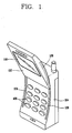
- FIG. 1 is a perspective view showing a slide open and close type portable terminal in accordance with the conventional art.
- the conventional slide open and close type portable terminal comprises: a display unit 102 having an LCD 110 for displaying each kind of information; a body unit 104 slidably mounted at the display unit 102 and having each kind of adjustment key 106 at the front surface thereof; and sliding units 126 and 128 installed between the display unit 102 and the body unit 104 for slidably opening and closing the display unit 102.
- the sliding units 126 and 128 are composed of: a guide groove 126 formed at both lateral surfaces of the body unit 104 in a longitudinal direction; and a guide rail 128 formed at both edges of the display unit 102 and inserted into the guide groove 126 thus to be moved in a longitudinal direction.
- the sliding units 126 and 128 of the conventional portable terminal are open when the user manually pushes the display unit 102 in a longitudinal direction, and are closed when the user manually pulls the display unit 102 in the opposite direction to the first direction.
- the user has to manually open the sliding units by pushing the display unit in a longitudinal direction and close the sliding units by pushing the display unit in the opposite direction to the first direction thereby to have inconvenience in using.
- a further slide-type terminal of the above-described kind is known from US 2001/009847 A1 .
- a body unit of the terminal is provided with control buttons, activation of which causes a display unit of the terminal to slide open or close.
- US 2003/003962 A1 discloses a similar portable phone comprising an open/close button, pressing of which activates a piezoelectric actuator to trigger a front cover of the phone to open or close automatically.
- EP 1 148 692 A2 concerns a portable electronic device having a user interface that is protected by a motorised slide.
- the motor can be started by a force sensor which is able to detect a pushing/pulling action of a slidable cover.
- the present invention provides a portable terminal having all the features of claim 1. Preferred embodiments are given in the dependent sub-claims.
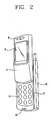
- FIG. 2 is a perspective view of a slide open and close type portable terminal according to one embodiment of the present invention
- FIG. 3 is a disassembled perspective view of the slide open and close type portable terminal according to one embodiment of the present invention.
- the slide open and close type portable terminal comprises: a body unit 2 provided with each kind of adjustment key 14; a display unit 4 slidably mounted at the body unit 2 and having an LCD 6 for displaying image information; and an open and close apparatus for automatically opening and closing the display unit 4.
- a speaker 8 is installed at the front surface of the display unit 4
- a mike 10 is installed at the front surface of the body unit 2
- a battery 12 is installed at the rear surface of the body unit 2.
- the slide open and close apparatus includes: a guide unit 20 formed between the rear surface of the display unit 4 and the front surface of the body unit 2 for guiding the display unit 4 to be slide-moved in a longitudinal direction; a driving unit 22 for generating a driving force so that the display unit 4 can be slide-moved; and a switching unit 24 for turning on/off the driving unit 22 by a user's adjustment.
- the guide unit 20 is composed of: a guide groove 16 formed at both edges of the rear surface of the display unit 4 in a longitudinal direction; and a guide hook 18 formed at the front surface of the body unit 2 and fitted-coupled to the guide groove 16 thus to be slide-moved along the guide groove 16 in a longitudinal direction.
- the guide hook 18 is protruded from the front surface of the body unit 2, and the end portion thereof is diverged to both sides.
- the guide hook 18 is formed to have an elastic force thereby to prevent from being detached from the inner side surface of the guide groove 16 when inserted into the guide groove 16.
- the driving unit 22 is composed of: a driving motor 26 mounted at the body unit 2 for generating a rotative force when a power is applied; a pinion gear 28 mounted at a rotational shaft of the driving motor 26 thus to be rotated together, and arranged to expose a part thereof to the upper surface of the body unit 2; and a rack gear 30 formed at the rear surface of the display unit 4 in a longitudinal direction and gear-coupled to the pinion gear 28.
- a penetration hole 32 for exposing the pinion gear 28 to outside is formed at the upper surface of the body unit 2.
- the driving unit 22 when a forward power source is applied to the driving motor 26, the pinion gear 28 is rotated in a forward direction, the rack gear 30 gear-coupled to the pinion gear 28 is linearly-moved, and the display unit 4 is opened. Also, when a reverse power source is applied to the driving motor 26, the pinion gear 28 is rotated in a reverse direction, the rack gear 30 is linearly-moved in a reverse direction, and the display unit 4 is closed.
- the switching unit 24 is composed of: a first switch operation groove 36 and a second switch operation groove 38 formed at the lower surface of the display unit 4; and a driving switch 40 protruded at the upper surface of the body unit 2, for turning off a power source at the time of being inserted into the first switch operation groove 36 and the second switch operation groove 38 and for turning on a power source at the time of being detached from the first and second switch operation grooves 36 and 38.
- the first switch operation groove 36 is formed at a position that the driving switch 40 is inserted when the display unit 4 is closed, and the second switch operation groove 38 is formed at a position that the driving switch 40 is inserted when the display unit 4 is open to the maximum.
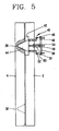
- the driving switch 40 is composed of: a switch lever 44 mounted in an insertion groove 42 formed at the body unit 2 and protruded at the upper surface of the body unit 2 with a certain height; a first movable terminal 48 connected to the lower side of the switch lever 44 and linearly-moved when the switch lever 44 is inclined upwardly thereby to be in contact with a first fixed terminal 46; and a second movable terminal 52 connected to the lower side of the switch lever 44 and linearly-moved when the switch lever 44 is inclined downwardly thereby to be in contact with a second fixed terminal 50.
- a ground movable terminal 54 is connected to the center of the lower side of the switch lever 44. When the switch lever 44 is positioned with an upright state, the ground movable terminal 54 is in contact with a ground fixed terminal 56.
- the first fixed terminal 46, the second fixed terminal 50, and the ground fixed terminal 56 are supported by a supporting plate 58.
- a spring 60 is installed between the supporting plate 58 and the switch lever 44 thereby to provide an elastic force to the switch lever 44.
- the switch lever 44 has a sectional surface of a triangle shape.
- the switch lever 44 When the switch lever 44 is inserted into the first switch operation groove 36 and the second switch operation groove 38, the ground movable terminal 54 and the ground fixed terminal 56 come in contact with each other and a power source is turned off. Also, when the user pushes the display unit 4 in an open direction, the switch lever 44 is upwardly inclined. When the first movable terminal 48 and the first fixed terminal 46 come in contact with each other, a forward power source is applied to the driving motor 26. When the user pushes the display unit 4 in a closed direction, the switch lever 44 is downwardly inclined. Also, when the second movable terminal 52 and the second fixed terminal 50 come in contact with each other, a reverse power source is applied to the driving motor 26.
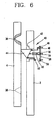
- FIGs. 5 to 8 are operational state views of the slide open and close type portable terminal according to one embodiment of the present invention.
- the switch lever 44 When the switch lever 44 is inserted into the second switch operation groove 38 accordingly as the display unit 4 is continuously moved, as shown in FIG. 7 , the switch lever 44 is positioned with an upright state, the first movable terminal 48 is detached from the first fixed terminal 46, and a power source to the driving motor 26 is shielded. At this time, the display unit 4 is in a maximum open state.
- FIG. 9 is a block diagram showing a switch unit of a slide open and close type portable terminal according to a second embodiment of the present invention.
- the switch unit of the open and close apparatus of a slide type portable terminal is composed of: a counter electromotive current detecting sensor 61 for detecting a counter electromotive current generated when a rotor of the driving motor 26 is forcibly rotated; and a controller 62 for driving the driving motor 26 in a forward direction or a reverse direction according to a signal applied from the counter electromotive current detecting sensor 61.
- the controller 62 applies a forward power source to the driving motor 26 thereby to drive the driving motor 26 in a forward direction (S20). According to this, the display unit 4 is automatically open (S30).
- a power source applied to the driving motor is shielded by a power shielding means and the display unit maintains the open state.
- the power shielding means is installed between the display unit and the body unit, and is switched when the display unit is in a maximum open state thereby to shield a power source (S40).
- a counter electromotive current in the reverse direction is detected by the counter electromotive current detecting sensor 61 and the signal is applied to the controller 62. Then, the controller 62 applies a reverse current to the driving motor 26 thereby to drive the driving motor 26 and to provide a driving force by which the display unit 4 is automatically closed (S50, S60).
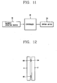
- FIG. 11 is a block diagram showing a switching unit of an open and close apparatus of a slide type portable terminal according to a third embodiment of the present invention
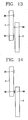
- FIG. 12 is a lateral view showing the switch unit of the open and close apparatus of the slide type portable terminal according to the third embodiment of the present invention.
- the switch unit of the open and close apparatus of a slide type portable terminal includes: a first magnet 80 and a second magnet 82 mounted at the lower surface of the display unit 4 with a certain interval in a longitudinal direction; a magnetic detecting sensor 84 mounted at the upper surface of the body unit 2 and opposite to either the first magnet 80 and the second magnet 82, for detecting a magnetic force of the first and second magnets 80 and 82; and a controller 86 for driving the driving motor 26 in a forward direction or a reverse direction by a signal applied from the magnetic detecting sensor 84.
- the switch unit of the open and close apparatus of a slide type portable terminal will be explained.
- the magnetic detecting sensor 84 is arranged to be opposite to the first magnet 80 thereby to detect a magnetic force of the first magnet 80.
- the controller 86 maintains the OFF state of the driving motor 26.
- the controller 86 drives the driving motor 26 in a forward direction by a signal applied from the magnetic detecting sensor 84 thereby to automatically open the display unit 4.
- the magnetic detecting sensor 84 is arranged to be opposite to the second magnet 82 thereby detect a magnetic force. Then, when the signal is applied to the controller 86, the controller 86 stops the driving motor 26 thereby to maintain the open state of the display unit 4.
- the magnetic detecting sensor 84 becomes far away from the second magnet 82 thereby not to detect a magnetic force. Also, when the signal is applied to the controller 86, the controller 86 drives the driving motor 26 in a reverse direction thus to provide a driving force by which the display unit 4 is closed.
- the magnetic detecting sensor 84 is arranged to be opposite to the first magnet 80, the magnetic detecting sensor 84 detects a magnetic force thus to apply the signal to the controller 86. According to this, the controller 86 turns off the driving motor 26 thereby to maintain the closed state of the display unit 4.
- the switch unit when the user pushes the display unit in an open direction, the switch unit is operated thus to drive the driving motor in a forward direction and thereby to automatically open the display unit. Also, when the user pushes the display unit in a closed direction, the switch unit is operated thus to drive the driving motor in a reverse direction thereby to automatically close the display unit. According to this, the user's convenience is increased.
Landscapes
- Engineering & Computer Science (AREA)
- Signal Processing (AREA)
- Computer Networks & Wireless Communication (AREA)
- Telephone Set Structure (AREA)
- Transceivers (AREA)
- Fittings On The Vehicle Exterior For Carrying Loads, And Devices For Holding Or Mounting Articles (AREA)
- Telephone Function (AREA)
Claims (10)
- Tragbares Endgerät mit:- einer Haupteinheit (2), die mit mindestens einer Taste (14) und einem Mikrofon (10) versehen ist,- einer Anzeigeeinheit (4), die verschiebbar an der Haupteinheit (2) angebracht ist und eine Anzeige (6) und einen Lautsprecher (8) aufweist,- einer Führungseinheit (20), die zwischen der Anzeigeeinheit (4) und der Haupteinheit (2) zum gleitverschieblichen Führen der Anzeigeeinheit (4) auf der Haupteinheit (2) ausgebildet ist,- einer Antriebseinheit (22) zum geradlinigen Bewegen der Anzeigeeinheit (4),- einer Schalteinheit (24) zum Verbinden einer Vorwärts-Energiequelle und einer Rückwärts-Energiequelle mit der Antriebseinheit (22),dadurch gekennzeichnet, dass die Vorwärts-Energiequelle beim Drücken der Anzeigeeinheit (4) in eine geöffnete Richtung mit der Antriebseinheit (22) verbunden wird und die Rückwärts-Energiequelle beim Drücken der Anzeigeeinheit (4) in eine geschlossene Richtung mit der Antriebseinheit (22) verbunden wird,
wobei der Beginn des Verbindens der Vorwärts- und Rückwärts-Energiequelle und das Eintreffen der Anzeigeeinheit (4) in dem geöffneten oder geschlossenen Zustand durch entweder eine erste Schalterfunktionsnut (36), eine zweite Schalterfunktionsnut (38) und einen Betriebsschalter (40), einen Gegenelektromotorischer-Strom-Erfassungssensor (61) oder einen Magnetismus-Erfassungssensor (84) erfasst wird, und
wobei die Führungseinheit (20) besteht aus- einer Führungsnut (16), die an der Rückseite der Anzeigeeinheit (4) in einer Längsrichtung ausgebildet ist, und- einem Führungshaken (18), der an der Vorderseite der Haupteinheit (2) ausgebildet ist, von der Vorderseite der Haupteinheit (2) hervorsteht und eingepasst mit der Führungsnut (16) gekoppelt ist, um so entlang der Führungsnut in einer Längsrichtung verschoben zu werden. - Endgerät nach Anspruch 1, wobei die Antriebseinheit (22) besteht aus:- einem Antriebsmotor (26), der an der Haupteinheit (2) zum Erzeugen einer Drehkraft angebracht ist, wenn eine Spannung angelegt wird,- einem Ritzel (28), das an einer Drehwelle des Antriebsmotors (26) angebracht ist, um dadurch zusammen gedreht zu werden, und- einer Zahnstange (30), die in einer Längsrichtung an der Rückseite der Anzeigeeinheit (4) ausgebildet und mit dem Zahnrad (28) antriebsgekoppelt ist.
- Endgerät nach Anspruch 2, wobei die Schalteinheit besteht aus:- ersten und zweiten Schalterfunktionsnuten (36, 38), die mit einem gewissen Abstand in einer Längsrichtung an der Anzeigeeinheit (4) ausgebildet sind, und- einem Betriebsschalter (40), der an der Vorderseite der Haupteinheit (2) angebracht ist zum Ausschalten einer Energiequelle dann, wenn er in die ersten und zweiten Schalterfunktionsnuten (36, 38) eingefügt ist, und zum Betreiben des Antriebsmotors (26) in einer Vorwärtsrichtung oder einer Rückwärtsrichtung dann, wenn er aus den ersten und zweiten Schalterfunktionsnuten (36, 38) entfernt ist.
- Endgerät nach Anspruch 3, wobei der Betriebsschalter (40) besteht aus:- einem Schalthebel (44), der an der Oberseite der Haupteinheit (2) angebracht ist, um nach außen freizuliegen,- einem ersten bewegbaren Anschluss (48), der mit der Unterseite des Schalthebels (44) verbunden ist und geradlinig bewegt wird, wenn der Schalthebel (44) in eine Richtung gekippt wird, um eine Vorwärts-Energiequelle mit dem Antriebsmotor (26) zu verbinden, und- einem zweiten bewegbaren Anschluss (52), der mit der Unterseite des Schalthebels (44) verbunden ist und geradlinig bewegt wird, wenn der Schalthebel (44) in eine andere Richtung gekippt wird, um eine Rückwärts-Energiequelle mit dem Antriebsmotor (26) zu verbinden.
- Endgerät nach Anspruch 4, bei dem der Betriebsschalter (40) ferner aufweist:- einen ersten feststehenden Anschluss (46), der den ersten bewegbaren Anschluss (48) kontaktiert, und- einen zweiten feststehenden Anschluss (50), der den zweiten bewegbaren Anschluss (52) kontaktiert.
- Endgerät nach Anspruch 5, bei dem die ersten und zweiten feststehenden Anschlüsse (46, 50) von einer Stützplatte (58) getragen werden, wobei eine Feder (60) zum Bereitstellen einer Federkraft an dem Schalthebel (44) zwischen der Stützplatte (58) und dem Schalthebel (44) angebracht ist.
- Endgerät nach Anspruch 2, bei dem die Antriebseinheit als ein Gegenelektromotorischer-Strom-Erfassungssensor (61) zum Erfassen eines gegenelektromotorischen Stroms ausgebildet ist, der erzeugt wird, wenn ein Rotor des Antriebsmotors (26) unter Krafteinwirkung gedreht wird und dabei den Antriebsmotor (26) in eine Vorwärtsrichtung oder eine Rückwärtsrichtung antreibt.
- Endgerät nach Anspruch 7, bei dem der Gegenelektromotorischer-Strom-Erfassungssensor (61) ein Sensor zum Erfassen eines gegenelektromotorischen Stroms ist, der erzeugt wird, wenn der Rotor des Antriebsmotors (26) entsprechend unter Krafteinwirkung gedreht wird, wenn die Anzeigeeinheit (4) in eine geöffnete Richtung oder eine geschlossene Richtung gedrückt wird, wodurch das Signal an eine Steuerung (62) angelegt wird.
- Endgerät nach Anspruch 2, bei dem die Schalteinheit enthält:- einen ersten Magneten (80) und einen zweiten Magneten (82), die mit einem gewissen Abstand in einer Längsrichtung an der Unterseite der Anzeigeeinheit (4) angebracht sind, und- einen Magnetismus-Erfassungssensor (84), der an der Vorderseite der Haupteinheit (2) und gegenüber entweder dem ersten Magneten (80) oder dem zweiten Magneten (82) angebracht ist, um eine magnetische Kraft der ersten und zweiten Magneten zu erfassen.
- Endgerät nach Anspruch 9, bei dem der erste Magnet (80) an einer Stelle angebracht ist, bei der er gegenüber dem Magnetismus-Erfassungssensor (84) angeordnet ist, wenn die Anzeigeeinheit (4) geschlossen ist, und der zweite Magnet (82) an einer Stelle angebracht ist, bei der er gegenüber dem Magnetismus-Erfassungssensor (84) angeordnet ist, wenn die Anzeigeeinheit (84) geöffnet ist.
Applications Claiming Priority (2)
| Application Number | Priority Date | Filing Date | Title |
|---|---|---|---|
| KR10-2003-0046922A KR100531880B1 (ko) | 2003-07-10 | 2003-07-10 | 슬라이드형 휴대용 단말기의 개폐 장치 |
| KR2003046922 | 2003-07-10 |
Publications (3)
| Publication Number | Publication Date |
|---|---|
| EP1496675A2 EP1496675A2 (de) | 2005-01-12 |
| EP1496675A3 EP1496675A3 (de) | 2005-01-19 |
| EP1496675B1 true EP1496675B1 (de) | 2008-12-24 |
Family
ID=33448373
Family Applications (1)
| Application Number | Title | Priority Date | Filing Date |
|---|---|---|---|
| EP04015395A Expired - Lifetime EP1496675B1 (de) | 2003-07-10 | 2004-06-30 | Verschiebbares bewegliches Telefon mit Motor |
Country Status (7)
| Country | Link |
|---|---|
| US (1) | US7428430B2 (de) |
| EP (1) | EP1496675B1 (de) |
| JP (1) | JP3958759B2 (de) |
| KR (1) | KR100531880B1 (de) |
| CN (1) | CN100473077C (de) |
| AT (1) | ATE418837T1 (de) |
| DE (1) | DE602004018576D1 (de) |
Cited By (1)
| Publication number | Priority date | Publication date | Assignee | Title |
|---|---|---|---|---|
| EP3926933A4 (de) * | 2019-02-14 | 2022-11-16 | LG Electronics Inc. | Mobiles endgerät |
Families Citing this family (30)
| Publication number | Priority date | Publication date | Assignee | Title |
|---|---|---|---|---|
| KR100608726B1 (ko) * | 2003-12-09 | 2006-08-04 | 엘지전자 주식회사 | 양방향 슬라이드형 휴대용 단말기 |
| KR100664983B1 (ko) * | 2004-06-23 | 2007-01-09 | 삼성전기주식회사 | 자동/반자동/수동 슬라이드형 이동통신단말기 |
| KR100677395B1 (ko) * | 2004-11-18 | 2007-02-02 | 엘지전자 주식회사 | 슬라이드 모듈 및 이를 구비한 슬라이드형 이동통신 단말기 |
| USD531977S1 (en) * | 2005-01-26 | 2006-11-14 | Samsung Electronics Co., Ltd. | Portable phone |
| EP1867143B1 (de) * | 2005-04-06 | 2011-11-02 | Nokia Corporation | Erweiterbares mobiles elektronisches gerät |
| USD530698S1 (en) * | 2005-04-27 | 2006-10-24 | Samsung Electronics Co., Ltd. | Mobile phone |
| TWI275004B (en) * | 2005-08-16 | 2007-03-01 | Asustek Comp Inc | Foldable electronic device |
| KR100754590B1 (ko) * | 2005-08-25 | 2007-09-05 | 삼성전자주식회사 | 휴대용 단말기의 개폐 장치 |
| KR100810763B1 (ko) * | 2005-09-07 | 2008-03-07 | (주)케이티에프테크놀로지스 | 슬라이드형 단말기 |
| CN1929725B (zh) * | 2005-09-09 | 2011-11-16 | 深圳富泰宏精密工业有限公司 | 铰链及使用该铰链的便携式电子装置 |
| US7507044B2 (en) | 2005-09-19 | 2009-03-24 | Nokia Corporation | Portable electronic device |
| KR100713411B1 (ko) | 2005-10-07 | 2007-05-04 | 삼성전자주식회사 | 휴대용 통신 장치 |
| US7467001B2 (en) * | 2005-12-30 | 2008-12-16 | Inventec Corporation | Handheld electronic device having a replaceable glass cover for LCD thereof |
| US7606043B2 (en) * | 2006-06-28 | 2009-10-20 | Nokia Corporation | Rocker key in a portable electronic device |
| USD558173S1 (en) * | 2006-08-11 | 2007-12-25 | Kyocera Wireless Corp. | Slide phone |
| KR100800770B1 (ko) * | 2006-09-07 | 2008-02-01 | 삼성전자주식회사 | 슬라이딩형 휴대용 단말기 |
| TW200907188A (en) * | 2007-08-02 | 2009-02-16 | Benq Corp | Sliding mechanism and method thereof and electronic device using the same |
| US8046033B2 (en) * | 2007-09-17 | 2011-10-25 | Lg Electronics Inc. | Mobile terminal |
| US7844305B2 (en) * | 2007-10-19 | 2010-11-30 | Motorola, Inc. | Method and apparatus for generating power in a mobile communication device |
| JP2010010847A (ja) * | 2008-06-24 | 2010-01-14 | Fujitsu Ltd | 装置並びに携帯端末装置及び回転支持部品 |
| CN101742859A (zh) * | 2008-11-20 | 2010-06-16 | 深圳富泰宏精密工业有限公司 | 便携式电子装置 |
| US20100194503A1 (en) * | 2009-02-05 | 2010-08-05 | Nokia Corporation | Magnetic actuation mechanism |
| CN104301457A (zh) * | 2013-07-15 | 2015-01-21 | 鸿富锦精密工业(深圳)有限公司 | 滑盖式电子设备 |
| US9405325B2 (en) * | 2014-01-03 | 2016-08-02 | Lg Electronics Inc. | Portable terminal |
| US9660685B1 (en) * | 2016-02-23 | 2017-05-23 | Htc Corporation | Electronic device and key module |
| CN107665790B (zh) * | 2016-07-28 | 2019-07-26 | 长城汽车股份有限公司 | 车窗开关 |
| CN111093337B (zh) * | 2018-10-23 | 2021-09-07 | 北京小米移动软件有限公司 | 滑动移动终端 |
| CN111093338B (zh) * | 2018-10-23 | 2021-11-16 | 北京小米移动软件有限公司 | 滑动移动终端 |
| KR102224748B1 (ko) * | 2019-02-13 | 2021-03-08 | 주식회사 케이티앤지 | 자기 센서를 포함하는 에어로졸 생성 장치 및 그 작동 방법 |
| US11165897B2 (en) * | 2019-02-14 | 2021-11-02 | Lg Electronics Inc. | Roll-slide mobile terminal |
Family Cites Families (24)
| Publication number | Priority date | Publication date | Assignee | Title |
|---|---|---|---|---|
| GB2235606B (en) * | 1989-08-24 | 1994-03-30 | Technophone Ltd | Portable telephone |
| KR950006706B1 (ko) * | 1992-06-16 | 1995-06-21 | 대우전자주식회사 | 휴대용 전화기 |
| EP0637021B1 (de) * | 1993-07-28 | 1998-12-02 | SANYO ELECTRIC Co., Ltd. | Kassettenladevorrichtung |
| US5783915A (en) * | 1995-01-20 | 1998-07-21 | Matsushita Electric Industrial Co., Ltd. | Linear actuating apparatus |
| JP3045223B2 (ja) * | 1996-10-04 | 2000-05-29 | タナシン電機株式会社 | ディスク再生装置 |
| FI112759B (fi) * | 1998-03-18 | 2003-12-31 | Nokia Corp | Teleskooppipuhelin |
| US6483445B1 (en) * | 1998-12-21 | 2002-11-19 | Intel Corporation | Electronic device with hidden keyboard |
| GB2353170A (en) * | 1999-08-06 | 2001-02-14 | Nokia Mobile Phones Ltd | Slide assembly for a communication unit |
| US6397078B1 (en) * | 1999-08-27 | 2002-05-28 | Young S. Kim | Combined mobile telephone and personal digital assistant |
| US6980840B2 (en) * | 2000-01-24 | 2005-12-27 | Lg Electronics Inc. | Drawer-type mobile phone |
| KR100347712B1 (ko) * | 2000-01-24 | 2002-08-07 | 엘지정보통신주식회사 | 드로어 타입 휴대전화기 |
| FI20000931A7 (fi) * | 2000-04-18 | 2001-10-19 | Nokia Corp | Kannettava elektroninen laite |
| KR100454485B1 (ko) * | 2000-08-18 | 2004-10-28 | 삼성전자주식회사 | 길이방향으로 신장가능한 셀룰러 폰 |
| KR100417248B1 (ko) * | 2001-03-22 | 2004-02-05 | 에스케이텔레텍주식회사 | 슬라이드 모듈을 이용한 슬라이드 타입 휴대폰 |
| US20030003962A1 (en) * | 2001-06-29 | 2003-01-02 | Tan Vooi-Kia | Automatic sliding machanism for portable electronic product, particularly for a sliding front cover of a mobile phone |
| JP2003179678A (ja) | 2001-10-03 | 2003-06-27 | Nec Corp | 携帯電話機 |
| JP2003319042A (ja) * | 2002-04-25 | 2003-11-07 | Matsushita Electric Ind Co Ltd | 携帯端末機器 |
| KR100484732B1 (ko) * | 2002-11-19 | 2005-04-22 | 삼성전자주식회사 | 슬라이딩 타입 휴대용 무선 단말기 |
| EP1570333B1 (de) * | 2002-11-21 | 2014-04-02 | Microsoft Corporation | Datenverarbeitungseinrichtung mit einstellbarer anzeige und eingabeeinrichtungen mit mehreren orientierungen |
| KR100501188B1 (ko) * | 2003-03-19 | 2005-07-18 | 삼성전기주식회사 | 자동구동형 슬라이드폰, 슬라이드폰의 자동구동방법, 및자동구동형 슬라이드폰의 착신신호감지방법 |
| KR100500126B1 (ko) * | 2003-04-01 | 2005-07-11 | 삼성전기주식회사 | 휴대전화기 |
| FI118669B (fi) * | 2003-04-01 | 2008-01-31 | Samsung Electro Mech | Liukutyyppinen matkapuhelin ja liukumismenetelmä siihen |
| US7071916B2 (en) * | 2003-09-29 | 2006-07-04 | Danger, Inc. | User input configurations for a data processing device |
| KR100724400B1 (ko) * | 2003-12-20 | 2007-06-04 | 엘지전자 주식회사 | 자석을 이용한 휴대용 단말기의 슬라이드 개폐장치 |
-
2003
- 2003-07-10 KR KR10-2003-0046922A patent/KR100531880B1/ko not_active Expired - Fee Related
-
2004
- 2004-06-30 DE DE602004018576T patent/DE602004018576D1/de not_active Expired - Lifetime
- 2004-06-30 EP EP04015395A patent/EP1496675B1/de not_active Expired - Lifetime
- 2004-06-30 AT AT04015395T patent/ATE418837T1/de not_active IP Right Cessation
- 2004-07-05 JP JP2004198501A patent/JP3958759B2/ja not_active Expired - Fee Related
- 2004-07-09 CN CNB2004100698113A patent/CN100473077C/zh not_active Expired - Fee Related
- 2004-07-09 US US10/888,604 patent/US7428430B2/en not_active Expired - Fee Related
Cited By (3)
| Publication number | Priority date | Publication date | Assignee | Title |
|---|---|---|---|---|
| EP3926933A4 (de) * | 2019-02-14 | 2022-11-16 | LG Electronics Inc. | Mobiles endgerät |
| EP3925200A4 (de) * | 2019-02-14 | 2022-12-28 | LG Electronics Inc. | Mobiles endgerät |
| EP4579391A3 (de) * | 2019-02-14 | 2025-09-10 | LG Electronics Inc. | Mobiles endgerät |
Also Published As
| Publication number | Publication date |
|---|---|
| ATE418837T1 (de) | 2009-01-15 |
| CN100473077C (zh) | 2009-03-25 |
| EP1496675A3 (de) | 2005-01-19 |
| US20050009572A1 (en) | 2005-01-13 |
| CN1578343A (zh) | 2005-02-09 |
| KR20050006932A (ko) | 2005-01-17 |
| DE602004018576D1 (de) | 2009-02-05 |
| EP1496675A2 (de) | 2005-01-12 |
| JP2005033794A (ja) | 2005-02-03 |
| KR100531880B1 (ko) | 2005-11-29 |
| US7428430B2 (en) | 2008-09-23 |
| JP3958759B2 (ja) | 2007-08-15 |
Similar Documents
| Publication | Publication Date | Title |
|---|---|---|
| EP1496675B1 (de) | Verschiebbares bewegliches Telefon mit Motor | |
| KR100608726B1 (ko) | 양방향 슬라이드형 휴대용 단말기 | |
| US6748249B1 (en) | Electronic device with a sliding lid | |
| US7363065B2 (en) | Automatic sliding-type mobile communication terminal, method of automatically driving sliding-type mobile communication terminal, and method of detecting incoming call to sliding-type mobile communication terminal | |
| US6782273B2 (en) | Portable wireless apparatus | |
| EP1926289B1 (de) | Tragbare elektronische Vorrichtung | |
| US8014137B2 (en) | Electronic apparatus having movable parts | |
| KR100724400B1 (ko) | 자석을 이용한 휴대용 단말기의 슬라이드 개폐장치 | |
| EP1517520A2 (de) | Verschiebbares mobiles Kommunikationsendgerät | |
| EP1744521B1 (de) | Mobilfunkgerät mit drehbarer Kamera | |
| JP2006071088A (ja) | 自動/手動スライド型通信端末機 | |
| JP3678672B2 (ja) | 折り畳み型情報機器 | |
| KR20000047803A (ko) | 스위치 장치 | |
| EP1233596A2 (de) | Vorrichtung und Verfahren zur automatischen oder manuellen Steuerung der Öffnung und Schliessung einer Unterteile in einem klappbaren Mobilkommunikationsendgerät | |
| EP2148494B1 (de) | Elektronische Vorrichtung mit schwenkbarem Bauteil | |
| US20020061733A1 (en) | Unfolding apparatus for foldable electronic device | |
| KR20060132350A (ko) | 자기력을 이용한 회전장치를 구비한 휴대용 단말기 | |
| KR100538337B1 (ko) | 폴더 자동 구동장치가 구비된 휴대 전화기 | |
| KR101271533B1 (ko) | 휴대 단말기 | |
| KR100651208B1 (ko) | 절첩식 카메라를 구비한 개인휴대단말기 | |
| KR101166265B1 (ko) | 슬라이드형 이동통신 단말기 | |
| TW201029426A (en) | Electronic device | |
| KR20050070221A (ko) | 휴대용 단말기의 개폐장치 | |
| KR20050100840A (ko) | 전자기력에 의해 자동개폐가 가능한 슬라이드형 휴대폰 | |
| KR20060007859A (ko) | 자기력을 이용한 슬라이드 개폐장치를 구비한 휴대용 단말기 |
Legal Events
| Date | Code | Title | Description |
|---|---|---|---|
| PUAI | Public reference made under article 153(3) epc to a published international application that has entered the european phase |
Free format text: ORIGINAL CODE: 0009012 |
|
| PUAL | Search report despatched |
Free format text: ORIGINAL CODE: 0009013 |
|
| 17P | Request for examination filed |
Effective date: 20040630 |
|
| AK | Designated contracting states |
Kind code of ref document: A2 Designated state(s): AT BE BG CH CY CZ DE DK EE ES FI FR GB GR HU IE IT LI LU MC NL PL PT RO SE SI SK TR |
|
| AX | Request for extension of the european patent |
Extension state: AL HR LT LV MK |
|
| AK | Designated contracting states |
Kind code of ref document: A3 Designated state(s): AT BE BG CH CY CZ DE DK EE ES FI FR GB GR HU IE IT LI LU MC NL PL PT RO SE SI SK TR |
|
| AX | Request for extension of the european patent |
Extension state: AL HR LT LV MK |
|
| RIN1 | Information on inventor provided before grant (corrected) |
Inventor name: KWON, KAP JOO Inventor name: AHN, BYUNG-JIN |
|
| 17Q | First examination report despatched |
Effective date: 20050623 |
|
| AKX | Designation fees paid |
Designated state(s): AT BE BG CH CY CZ DE DK EE ES FI FR GB GR HU IE IT LI LU MC NL PL PT RO SE SI SK TR |
|
| 17Q | First examination report despatched |
Effective date: 20050623 |
|
| RIN1 | Information on inventor provided before grant (corrected) |
Inventor name: KWON, KAP JOO Inventor name: AHN, BYUNG-JIN |
|
| GRAP | Despatch of communication of intention to grant a patent |
Free format text: ORIGINAL CODE: EPIDOSNIGR1 |
|
| RIN1 | Information on inventor provided before grant (corrected) |
Inventor name: KWON, KAP JOO Inventor name: AHN, BYUNG-JIN |
|
| GRAS | Grant fee paid |
Free format text: ORIGINAL CODE: EPIDOSNIGR3 |
|
| GRAA | (expected) grant |
Free format text: ORIGINAL CODE: 0009210 |
|
| AK | Designated contracting states |
Kind code of ref document: B1 Designated state(s): AT BE BG CH CY CZ DE DK EE ES FI FR GB GR HU IE IT LI LU MC NL PL PT RO SE SI SK TR |
|
| REG | Reference to a national code |
Ref country code: GB Ref legal event code: FG4D |
|
| REG | Reference to a national code |
Ref country code: CH Ref legal event code: EP |
|
| REG | Reference to a national code |
Ref country code: IE Ref legal event code: FG4D |
|
| REF | Corresponds to: |
Ref document number: 602004018576 Country of ref document: DE Date of ref document: 20090205 Kind code of ref document: P |
|
| PG25 | Lapsed in a contracting state [announced via postgrant information from national office to epo] |
Ref country code: PL Free format text: LAPSE BECAUSE OF FAILURE TO SUBMIT A TRANSLATION OF THE DESCRIPTION OR TO PAY THE FEE WITHIN THE PRESCRIBED TIME-LIMIT Effective date: 20081224 Ref country code: SI Free format text: LAPSE BECAUSE OF FAILURE TO SUBMIT A TRANSLATION OF THE DESCRIPTION OR TO PAY THE FEE WITHIN THE PRESCRIBED TIME-LIMIT Effective date: 20081224 Ref country code: FI Free format text: LAPSE BECAUSE OF FAILURE TO SUBMIT A TRANSLATION OF THE DESCRIPTION OR TO PAY THE FEE WITHIN THE PRESCRIBED TIME-LIMIT Effective date: 20081224 |
|
| PG25 | Lapsed in a contracting state [announced via postgrant information from national office to epo] |
Ref country code: ES Free format text: LAPSE BECAUSE OF FAILURE TO SUBMIT A TRANSLATION OF THE DESCRIPTION OR TO PAY THE FEE WITHIN THE PRESCRIBED TIME-LIMIT Effective date: 20090404 Ref country code: BE Free format text: LAPSE BECAUSE OF FAILURE TO SUBMIT A TRANSLATION OF THE DESCRIPTION OR TO PAY THE FEE WITHIN THE PRESCRIBED TIME-LIMIT Effective date: 20081224 Ref country code: RO Free format text: LAPSE BECAUSE OF FAILURE TO SUBMIT A TRANSLATION OF THE DESCRIPTION OR TO PAY THE FEE WITHIN THE PRESCRIBED TIME-LIMIT Effective date: 20081224 Ref country code: EE Free format text: LAPSE BECAUSE OF FAILURE TO SUBMIT A TRANSLATION OF THE DESCRIPTION OR TO PAY THE FEE WITHIN THE PRESCRIBED TIME-LIMIT Effective date: 20081224 Ref country code: BG Free format text: LAPSE BECAUSE OF FAILURE TO SUBMIT A TRANSLATION OF THE DESCRIPTION OR TO PAY THE FEE WITHIN THE PRESCRIBED TIME-LIMIT Effective date: 20090324 |
|
| PG25 | Lapsed in a contracting state [announced via postgrant information from national office to epo] |
Ref country code: CZ Free format text: LAPSE BECAUSE OF FAILURE TO SUBMIT A TRANSLATION OF THE DESCRIPTION OR TO PAY THE FEE WITHIN THE PRESCRIBED TIME-LIMIT Effective date: 20081224 Ref country code: AT Free format text: LAPSE BECAUSE OF FAILURE TO SUBMIT A TRANSLATION OF THE DESCRIPTION OR TO PAY THE FEE WITHIN THE PRESCRIBED TIME-LIMIT Effective date: 20081224 Ref country code: SE Free format text: LAPSE BECAUSE OF FAILURE TO SUBMIT A TRANSLATION OF THE DESCRIPTION OR TO PAY THE FEE WITHIN THE PRESCRIBED TIME-LIMIT Effective date: 20090324 Ref country code: PT Free format text: LAPSE BECAUSE OF FAILURE TO SUBMIT A TRANSLATION OF THE DESCRIPTION OR TO PAY THE FEE WITHIN THE PRESCRIBED TIME-LIMIT Effective date: 20090525 |
|
| PG25 | Lapsed in a contracting state [announced via postgrant information from national office to epo] |
Ref country code: SK Free format text: LAPSE BECAUSE OF FAILURE TO SUBMIT A TRANSLATION OF THE DESCRIPTION OR TO PAY THE FEE WITHIN THE PRESCRIBED TIME-LIMIT Effective date: 20081224 |
|
| PG25 | Lapsed in a contracting state [announced via postgrant information from national office to epo] |
Ref country code: DK Free format text: LAPSE BECAUSE OF FAILURE TO SUBMIT A TRANSLATION OF THE DESCRIPTION OR TO PAY THE FEE WITHIN THE PRESCRIBED TIME-LIMIT Effective date: 20081224 |
|
| PLBE | No opposition filed within time limit |
Free format text: ORIGINAL CODE: 0009261 |
|
| STAA | Information on the status of an ep patent application or granted ep patent |
Free format text: STATUS: NO OPPOSITION FILED WITHIN TIME LIMIT |
|
| 26N | No opposition filed |
Effective date: 20090925 |
|
| PG25 | Lapsed in a contracting state [announced via postgrant information from national office to epo] |
Ref country code: MC Free format text: LAPSE BECAUSE OF NON-PAYMENT OF DUE FEES Effective date: 20090630 |
|
| REG | Reference to a national code |
Ref country code: CH Ref legal event code: PL |
|
| PG25 | Lapsed in a contracting state [announced via postgrant information from national office to epo] |
Ref country code: CH Free format text: LAPSE BECAUSE OF NON-PAYMENT OF DUE FEES Effective date: 20090630 Ref country code: LI Free format text: LAPSE BECAUSE OF NON-PAYMENT OF DUE FEES Effective date: 20090630 Ref country code: IE Free format text: LAPSE BECAUSE OF NON-PAYMENT OF DUE FEES Effective date: 20090630 |
|
| PG25 | Lapsed in a contracting state [announced via postgrant information from national office to epo] |
Ref country code: GR Free format text: LAPSE BECAUSE OF FAILURE TO SUBMIT A TRANSLATION OF THE DESCRIPTION OR TO PAY THE FEE WITHIN THE PRESCRIBED TIME-LIMIT Effective date: 20090325 |
|
| PG25 | Lapsed in a contracting state [announced via postgrant information from national office to epo] |
Ref country code: LU Free format text: LAPSE BECAUSE OF NON-PAYMENT OF DUE FEES Effective date: 20090630 |
|
| PG25 | Lapsed in a contracting state [announced via postgrant information from national office to epo] |
Ref country code: HU Free format text: LAPSE BECAUSE OF FAILURE TO SUBMIT A TRANSLATION OF THE DESCRIPTION OR TO PAY THE FEE WITHIN THE PRESCRIBED TIME-LIMIT Effective date: 20090625 |
|
| PG25 | Lapsed in a contracting state [announced via postgrant information from national office to epo] |
Ref country code: TR Free format text: LAPSE BECAUSE OF FAILURE TO SUBMIT A TRANSLATION OF THE DESCRIPTION OR TO PAY THE FEE WITHIN THE PRESCRIBED TIME-LIMIT Effective date: 20081224 |
|
| PG25 | Lapsed in a contracting state [announced via postgrant information from national office to epo] |
Ref country code: CY Free format text: LAPSE BECAUSE OF FAILURE TO SUBMIT A TRANSLATION OF THE DESCRIPTION OR TO PAY THE FEE WITHIN THE PRESCRIBED TIME-LIMIT Effective date: 20081224 |
|
| REG | Reference to a national code |
Ref country code: FR Ref legal event code: PLFP Year of fee payment: 12 |
|
| PGFP | Annual fee paid to national office [announced via postgrant information from national office to epo] |
Ref country code: GB Payment date: 20150512 Year of fee payment: 12 Ref country code: DE Payment date: 20150513 Year of fee payment: 12 |
|
| PGFP | Annual fee paid to national office [announced via postgrant information from national office to epo] |
Ref country code: NL Payment date: 20150512 Year of fee payment: 12 Ref country code: FR Payment date: 20150514 Year of fee payment: 12 |
|
| PGFP | Annual fee paid to national office [announced via postgrant information from national office to epo] |
Ref country code: IT Payment date: 20160620 Year of fee payment: 13 |
|
| REG | Reference to a national code |
Ref country code: DE Ref legal event code: R119 Ref document number: 602004018576 Country of ref document: DE |
|
| REG | Reference to a national code |
Ref country code: NL Ref legal event code: MM Effective date: 20160701 |
|
| GBPC | Gb: european patent ceased through non-payment of renewal fee |
Effective date: 20160630 |
|
| REG | Reference to a national code |
Ref country code: FR Ref legal event code: ST Effective date: 20170228 |
|
| PG25 | Lapsed in a contracting state [announced via postgrant information from national office to epo] |
Ref country code: DE Free format text: LAPSE BECAUSE OF NON-PAYMENT OF DUE FEES Effective date: 20170103 Ref country code: FR Free format text: LAPSE BECAUSE OF NON-PAYMENT OF DUE FEES Effective date: 20160630 |
|
| PG25 | Lapsed in a contracting state [announced via postgrant information from national office to epo] |
Ref country code: GB Free format text: LAPSE BECAUSE OF NON-PAYMENT OF DUE FEES Effective date: 20160630 Ref country code: NL Free format text: LAPSE BECAUSE OF NON-PAYMENT OF DUE FEES Effective date: 20160701 |
|
| PG25 | Lapsed in a contracting state [announced via postgrant information from national office to epo] |
Ref country code: IT Free format text: LAPSE BECAUSE OF NON-PAYMENT OF DUE FEES Effective date: 20170630 |