EP1496694A2 - Bildverarbeitungssystem, Informationsspeichermedium und Bildverarbeitungsverfahren - Google Patents
Bildverarbeitungssystem, Informationsspeichermedium und Bildverarbeitungsverfahren Download PDFInfo
- Publication number
- EP1496694A2 EP1496694A2 EP04253761A EP04253761A EP1496694A2 EP 1496694 A2 EP1496694 A2 EP 1496694A2 EP 04253761 A EP04253761 A EP 04253761A EP 04253761 A EP04253761 A EP 04253761A EP 1496694 A2 EP1496694 A2 EP 1496694A2
- Authority
- EP
- European Patent Office
- Prior art keywords
- projection
- image
- sensing
- information
- distance
- Prior art date
- Legal status (The legal status is an assumption and is not a legal conclusion. Google has not performed a legal analysis and makes no representation as to the accuracy of the status listed.)
- Withdrawn
Links
- 238000012545 processing Methods 0.000 title claims abstract description 23
- 238000003672 processing method Methods 0.000 title claims description 7
- 238000012937 correction Methods 0.000 claims abstract description 54
- 230000003287 optical effect Effects 0.000 claims description 29
- 238000000034 method Methods 0.000 claims description 11
- 230000008569 process Effects 0.000 claims description 7
- 238000010586 diagram Methods 0.000 description 4
- 239000004973 liquid crystal related substance Substances 0.000 description 4
- 238000005401 electroluminescence Methods 0.000 description 2
- 238000003384 imaging method Methods 0.000 description 2
- 230000007246 mechanism Effects 0.000 description 2
- 238000010420 art technique Methods 0.000 description 1
- 230000005540 biological transmission Effects 0.000 description 1
- 239000006185 dispersion Substances 0.000 description 1
- 238000003702 image correction Methods 0.000 description 1
- 230000006872 improvement Effects 0.000 description 1
- 238000004519 manufacturing process Methods 0.000 description 1
- 239000000463 material Substances 0.000 description 1
- 239000011159 matrix material Substances 0.000 description 1
- 238000005259 measurement Methods 0.000 description 1
- 238000012986 modification Methods 0.000 description 1
- 230000004048 modification Effects 0.000 description 1
Images


Classifications
-
- H—ELECTRICITY
- H04—ELECTRIC COMMUNICATION TECHNIQUE
- H04N—PICTORIAL COMMUNICATION, e.g. TELEVISION
- H04N9/00—Details of colour television systems
- H04N9/12—Picture reproducers
- H04N9/31—Projection devices for colour picture display, e.g. using electronic spatial light modulators [ESLM]
- H04N9/3179—Video signal processing therefor
- H04N9/3185—Geometric adjustment, e.g. keystone or convergence
-
- G—PHYSICS
- G03—PHOTOGRAPHY; CINEMATOGRAPHY; ANALOGOUS TECHNIQUES USING WAVES OTHER THAN OPTICAL WAVES; ELECTROGRAPHY; HOLOGRAPHY
- G03B—APPARATUS OR ARRANGEMENTS FOR TAKING PHOTOGRAPHS OR FOR PROJECTING OR VIEWING THEM; APPARATUS OR ARRANGEMENTS EMPLOYING ANALOGOUS TECHNIQUES USING WAVES OTHER THAN OPTICAL WAVES; ACCESSORIES THEREFOR
- G03B21/00—Projectors or projection-type viewers; Accessories therefor
-
- H—ELECTRICITY
- H04—ELECTRIC COMMUNICATION TECHNIQUE
- H04N—PICTORIAL COMMUNICATION, e.g. TELEVISION
- H04N5/00—Details of television systems
- H04N5/74—Projection arrangements for image reproduction, e.g. using eidophor
-
- H—ELECTRICITY
- H04—ELECTRIC COMMUNICATION TECHNIQUE
- H04N—PICTORIAL COMMUNICATION, e.g. TELEVISION
- H04N9/00—Details of colour television systems
- H04N9/12—Picture reproducers
- H04N9/31—Projection devices for colour picture display, e.g. using electronic spatial light modulators [ESLM]
- H04N9/3191—Testing thereof
- H04N9/3194—Testing thereof including sensor feedback
Definitions
- the present invention relates to an image processing system, information storage medium and image processing method which can correct the distortion of an image.
- the projected image When an image is projected by an image projection device such as a projector and if the optical axis of the projected light is not coincident with a projection target such as a screen, the projected image may be distorted to create a so-called keystone distortion from image distortions in the vertical and horizontal directions.
- the image projection device must project a proper image after the distortion has been eliminated.
- the general image projection device having an image distortion correcting function includes an inclination sensor which can correct the image distortion in the vertical direction, but not the image distortion in the horizontal direction.
- a user In order to correct the distortion in the horizontal direction, a user must indicate four comer points in a screen by use of a mouse or the like so that the image projection device can semi-automatically correct the image distortion in the horizontal direction, based on the user's indications. It is troublesome for the user to indicate the four comer points in the screen through the mouse or the like.
- Japanese Patent Laid-Open Application No. 2001-61121 has proposed a projector device which comprises a projection plane capturing means for capturing the shape of the projection plane by associating coordinates of the projector's image with coordinates of the camera's image based on an image taken by a camera, the taken image being projected when a pattern image is displayed, and determining three-dimensional coordinate of the position where the pattern image is projected through triangulation, and an image correction means for performing corrections for inclination and magnification in the original inputted image according to the sensed shape of the projection plane.
- Japanese Patent Laid-Open Application No. 2001-61121 also describes that a known three-dimensional shape measuring device can be used as projection plane capturing means and that the projection plane sensing means are not essential for the invention thereof.
- the known three-dimensional shape measuring device requires two cameras, for example, when the triangulation is to be carried out. This makes the structure complicated and increases the manufacturing cost.
- the present invention is made in view of the above-mentioned problem and may provide an image processing system, information storage medium and image processing method, all of which can correct any distortion of an projected image by use of a single sensor for measuring the distance and angle between a reference projection point and a projection target.
- An image processing system includes:
- An information storage medium stores a computer-readable program which causes a computer to function as:
- An image processing method includes:
- the image processing system and the like can correct the distortions in the projected image by use of only a single sensor for measuring the distance and angle between the reference projection point and the projection target.
- the image processing system and the like can be applied to various kinds of projection targets such as walls, resulting in improvement of its versatility, since the distortions in the projected image can be corrected without using a frame of a screen and the like.
- the correction information generating means may have following functions of:
- this image processing method may include:
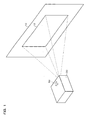
- FIG. 1 is schematic view showing a state when an image is projected.
- a projector 20 which is a kind of an image processing system projects an image toward a screen 10 which is a kind of a projection target. Thus, a projected image 12 is displayed on the screen 10.
- the projector 20 is not arranged directly in front of the screen 10. For such a reason, a distortion (e.g., a so-called keystone distortion) is occurred in the projected image 12.
- a distortion e.g., a so-called keystone distortion
- a sensor 60 which is part of a sensing means senses a region including the projected image 12.
- the projector 20 then derives a projection distance between the reference projection position of the projector 20 and each of four comers of the projected image 12 based on the sensing information from the sensor 60, and derives an angle between the optical axis in the projected light from the projector 20 and the screen 10.
- the projector 20 further determines a distortion of the projected image 12 based on the projection distances and corrects input image signals to correct the distortions in the projected image 12.
- FIG. 2 is a functional block diagram of the projector 20 according to one example of this embodiment.
- the projector 20 comprises a signal input section 110 for inputting image signals, a distortion correcting section 130 for correcting the inputted image signals so that the image distortion is corrected, a signal output section 160 for outputting the corrected image signals, an image projecting section 190 for projecting an image based on the image signals, the image projecting section 190 being a kind of projection means, and a calibration image information generating section 170 for generating calibration image information.
- the projector 20 also comprises a sensing section 180 for sensing a region including the projected image 12 through the imaging sensing plane to generate sensing information, a projection area information generating section 150 for determining the region of the projected image 12 in the sensing plane of the sensor 60, based on the sensing information and a correction information generating section 120 for generating distortion correction information.
- the sensor 60 is included in the sensing section 180.
- the image projecting section 190 comprises a spatial light modulator 192, a drive section 194 for driving the spatial light modulator 192, a light source 196 and a lens 198.
- the drive section 194 drives the spatial light modulator 192 based on the image signals from the signal output section 160.
- the image projecting section 190 projects light from a light source 196 through the spatial light modulator 192 and lens 198.
- the following means can be applied so that the functions of the respective sections in the projector 20 can be implemented into a computer.
- FIG. 3 is a hardware block diagram illustrating a projector according to this example of this embodiment.
- the signal input section 110 may be implemented, for example, by an A/D converter 930 or the like; the distortion correcting section 130 may be implemented, for example, by an image processing circuit 970, RAM 950, CPU 910 or the like; the signal output section 160 may be implemented, for example, by a D/A converter 940 or the like; the correction information generating section 120, projection area information generating section 150 and calibration image information generating section 170 may be, for example, by the image processing circuit 970, RAM 950 or the like; the sensing section 180 may be implemented, for example, by a CCD sensor, a CMOS sensor, an RGB sensor or the like; the spatial light modulator 192 may be implemented, for example, by a liquid crystal panel 920, a ROM 960 for storing a liquid crystal light valve driver for driving the liquid crystal panel 920 or the like.
- These sections can be configured to mutually deliver the information therebetween through a system bus 980.
- each of these sections may be implemented in a hardware manner such as circuits or in a software manner such as drivers.
- the computer may implement the function of the projection area information generating section 150 according to a program that has been stored in and is read out of an information storage medium 900, the program being operative for causing the computer to function as the projection area information generating section 150 and the like.
- Such an information storage medium 900 may be accomplished, for example, by CD-ROM, DVD-ROM, ROM, RAM, HDD or the like.
- the program may be read out of the information storage medium 900 through either of the contact or non-contact type reading mode.
- the aforementioned functions can be implemented by downloading a program or the like for implementing them from a host device or the like through a transmission channel.
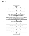
- FIG. 4 is a flow chart illustrating a flow of image processing according to this example of this embodiment.
- a manufacturer for the projector 20 has determined, prior to delivery of the projector 20, the relationship between the distances on the optical axis of the projected light between the reference projection position of the image projecting section 190 and four comers of the projected image 12 and the distances between coordinates in the sensing plane of the sensor 60 and stored it in the correction information generating section 120 as projection distance data.
- the manufacturer Prior to delivery of the projector 20, the manufacturer has also located the screen 10 at a shortest-distance position (first or temporary position) at which the whole calibration image (or the projected image 12) falls within the sensing range in the sensor 60 under a condition that the projector 20 is positioned directly in front of the screen 10.
- the projector 20 projects a calibration image toward the screen 10, derives the coordinates of the four comers of the projected image 12 on the sensing plane, and stores them as shortest-distance projection area information (step S1).
- the calibration image information generating section 170 generates image information for an all-white monochromatic calibration image (i.e., white-colored image as a whole).
- the signal output section 160 outputs the digital signals of the image information toward the image projecting section 190.
- the image projecting section 190 projects an all-white calibration image onto the screen 10, based on the digital signals. Thus, the all-white calibration image is displayed on the screen 10.
- the sensing section 180 senses a region including the projected image 12 through the imaging sensing plane to generate sensing information.
- the sensing information is one that indicates an image signal value which can generate a luminance value, XYZ value or the like for each pixel in the sensor 60.
- the XYZ value used herein is a kind of image signal value which is a device-independent color based on the International Standard defined by the Commission Internationale de l'Eclairage (CIE).
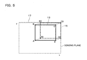
- FIG.5 is a schematic view illustrating the sensing plane 17 according to this example of this embodiment.
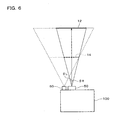
- FIG. 6 is a schematic view illustrating, in a plan view, a projection state according to this example of this embodiment.
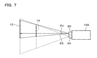
- FIG. 7 is a schematic view illustrating, in a side view, a state of projection according to this example of this embodiment.
- the sensing plane 17 shown in FIG. 5 is a plane at which the sensor 60 senses the image and also a region in which the sensing information of the sensor 60 is schematically shown in rectangular form. Specifically, the sensing plane 17 corresponds to, for example, that of a CCD sensor.
- the projected image 14 corresponds to the shortest-distance projection area 15 in the sensing plane 17, which is surrounded by four vertexes A0 to D0.
- the projected image 12 in the actual operating environment corresponds to the actual projection area 13 in the sensing plane 17, which is surrounded by four vertexes A to D.
- the projection area information generating section 150 generates shortest-distance projection area information (first or temporary projection area information) representing the coordinates of the four vertexes A0 to D0 of the shortest-distance projection area 15 in the sensing plane 17, based on the sensing information for the projected image 14 from the sensing section 180.
- the manufacturer has also sensed images through the sensor 60 while moving the projector 20 away from the screen 10 within a range of projection between the minimum and maximum distances.
- the maximum distance used herein is the longest distance on the optical axis of the projected light, which quality is assured by the maker, when the projector 20 is positioned directly in front of the screen 10.
- the correction information generating section 120 determines the projection area information within the range of projection between the minimum and maximum distances and the projection distance at each point of time.
- the correction information generating section 120 then computes inter-coordinate distances at the respective one of the sensed projection distances, each of the inter-coordinate distances representing a deviation (e.g., dots) between the coordinate of each of the four comers in the sensing plane 17 of the projected image 12 and the coordinate of each of the four comers of the projection image 12 when it is projected at the minimum distance.
- the correction information generating section 120 further generates and stores a two-dimensional lookup table in which the inter-coordinate distances are associated with the projection distance as projection distance data.
- the manufacturer can deliver the projector 20 which has stored the projection distance data in which the inter-coordinate distance between the projections at the minimum and maximum distances is associated with the projection distance as well as the shortest-distance projection area information.
- the projection area information generating section 150 When a user first uses the projector 20 in the actual operating environment, the projection area information generating section 150 generates the actual projection area information (second projection area information) representing the coordinates of the four vertexes A to D of the actual projection area 13 in the sensing plane 17, based on the sensing information for the projected image 12 from the sensing section 180 in the actual operating environment (step S2).
- the correction information generating section 120 then derives an inter-coordinate distance in the sensing plane 17 between each of the vertexes of the actual projection area 13 and corresponding one of the vertexes of the shortest-distance projection area 15, based on the shortest-distance projection area information and the actual projection area information (step S3).
- the correction information generating section 120 then derives the projection distance based on the inter-coordinate distance and projection distance data (step S4).
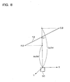
- FIG.8 is a schematic view illustrating a projection distance according to this example of this embodiment.
- FIG. 9 is a schematic view illustrating the data structure of the projection distance according to this example of this embodiment.
- the correction information generating section 120 derives a projection distance Ad, Bd, Cd or Dd on the Z-axis between a shortest-distance point between each of the vertexes A, B, C or D in the projected image 12 and the Z-axis, and the origin.
- the correction information generating section 120 derives a projection distance (Ad, Bd, Cd or Dd) to each of the four comers of the projected image 12, based on the derived inter-coordinate distances and the projection distance data indicative of the relationship between the derived inter-coordinate distances and the projection distances.
- a projection distance (Ad, Bd, Cd or Dd) to each of the four comers of the projected image 12, based on the derived inter-coordinate distances and the projection distance data indicative of the relationship between the derived inter-coordinate distances and the projection distances.
- the projection distance is equal to 1.5m if the inter-coordinate distance is zero dots.
- the projection distance data may be common to all the four vertexes or individual from one vertex to another.
- each half angle-of-view in the projection lens section 50 is ⁇ R on the right side; ⁇ L on the left side; ⁇ U on the upper side; or ⁇ D on the lower side as shown in FIGs. 6 and 7.
- the correction information generating section 120 also derives an angle ( ⁇ x in the horizontal direction or ⁇ y in the vertical direction) which is formed by the normal vector N and a directional vector (0, 0, 1) of the optical axis of the projection lens section 50 (step S5). This angle corresponds to an angle formed by the screen 10 and the optical axis of the projected light from the projector 20.
- the correction information generating section 120 further derives coordinates of four comers E, F, G and H in the corrected projection area by searching the coordinates of the four comers in the corrected projection area from correcting data based on this angle (i.e., ⁇ x or ⁇ y) (step S6).
- FIG. 10 is a schematic view illustrating four comer coordinates in a corrected projection area according to this example of this embodiment.
- FIG. 11 is correcting data illustrating four comer coordinates in a corrected projection area according to this example of this embodiment.
- the values of ⁇ x and ⁇ y are associated with the x-y coordinate of the respective one of the coordinates of the four comers E, F, G and H in the corrected projection area, as shown in FIG. 11. It is noted that the coordinates of the four comers E, F, G and H in the corrected projection area are coordinates in the spatial light modulator 192, for example.
- the correction information generating section 120 then generates image distortion correction information by using the x-y coordinate of the respective one of the coordinates E, F, G and H in the correcting data shown in FIG. 11 (step S7), and sends them to the distortion correcting section 130.
- the image distortion correction information used herein may correspond to information indicative of differential values between the coordinates of the four comers of the image before and after the distortion thereof is corrected, for example.
- the distortion correcting section 130 then corrects image signals to correct the image distortion, based on the image distortion correction information (step S8).
- the distortion correcting section 130 may indirectly correct the image signals by correcting the distortion correcting data such as lookup table or matrix, based on the image distortion correction information or may directly correct the image signals without the use of the distortion correcting data.
- the image projecting section 190 can project the image after the distortion thereof has been corrected.
- the distortion of the projected image 12 can be corrected by measuring the distance and angle between the point of the projection lens section 50 at which the light is projected and the screen 10 through only a single sensor 60.
- the manufacturer can provide an image processing system which is of a simpler structure produced in lower cost, in comparison with the prior art technique of detecting the three-dimensional coordinates of the projected image by use of a plurality of CCD cameras.
- the distortion of the projected image 12 can be corrected without use of the four corners in the screen 10.
- this embodiment may be applied to various kinds of projection targets (e.g., white board, wall or the like). Furthermore, this embodiment may be less influenced by the color and material of the projection target. According to this embodiment, thus, the versatility of the image processing system and the like can be more improved.
- the projector 20 can derive the projection distance based on the inter-coordinate distance between two corresponding points in the sensing plane 17 without using the directional information of coordinate by using the coordinates of the projected image 12 in the sensing plane 17 when the image is projected at the minimum distance.
- the projector 20 can more simply and easily derive the projection distance to correct the distortion of the projected image 12.
- the projector 20 may comprise a control means for automatically adjusting the focus based on the distance information between the projector 20 and the screen 10, which has been generated by the correction information generating section 120.
- a positioning mechanism e.g., an arm mechanism for the sensor 60 may be provided so that upon calibration, the sensor 60 senses the projected image 12 under a state that the projection lens section 50 is located farther apart from the sensor 60.
- the measurement accuracy of the sensor 60 can be more improved.
- the projector 20 generates the actual projection area information based on the sensing information in the actual operating condition and also generates the temporary projection area information based on the sensing information at the minimum distance in which the calibration image falls within the sensing range.
- the temporary projection area information may be generated based on the sensing information which are obtained when the projector 20 and screen 10 are placed under such a state that the calibration image falls within the sensing range and under such a state that the positional relationship therebetween is different from the actual operating state, rather than the minimum distance.
- the two-dimensional lookup table is used as the projection distance data in which the projection distance is associated with the inter-coordinate distance.
- a function of inputting the inter-coordinate distance and outputting the projection distance may be used.
- the projector 20 may project and sense an all-black calibration image (the entire image being black-colored) and also an all-white calibration image, compare the ratios of luminance value between each pair of adjacent pixels included in the sensing information, and determine a pixel area having its luminance ratio more than a predetermined value as a projection area.
- the projector 20 will less be influenced by any damage in the screen 10 or by any ambient light or the like relative to the screen 10. Therefore, the projector 20 can more precisely determine the projection area.
- the present invention is effective for an image processing system for CRT (Cathode Ray Tube) displays, LED (Light Emitting Diode) displays, EL (Electro Luminescence) displays and other displays, in addition to the projector 20.
- CRT Cathode Ray Tube
- LED Light Emitting Diode
- EL Electro Luminescence
- the projector 20 may be of liquid crystal projector, a DMD (Digital Micromirror Device) projector, for example.
- DMD Digital Micromirror Device
- DMD is a trademark possessed by Texas Instruments Inc. of the USA.
- the function of the projector 20 may be accomplished solely by the projector 20 or in dispersion by a plurality of decentralized processing units (e.g., one projector and one PC).
Landscapes
- Engineering & Computer Science (AREA)
- Multimedia (AREA)
- Signal Processing (AREA)
- Physics & Mathematics (AREA)
- Geometry (AREA)
- General Physics & Mathematics (AREA)
- Projection Apparatus (AREA)
- Transforming Electric Information Into Light Information (AREA)
Applications Claiming Priority (2)
| Application Number | Priority Date | Filing Date | Title |
|---|---|---|---|
| JP2003273358A JP2005033703A (ja) | 2003-07-11 | 2003-07-11 | 画像処理システム、プロジェクタ、プログラム、情報記憶媒体および画像処理方法 |
| JP2003273358 | 2003-07-11 |
Publications (2)
| Publication Number | Publication Date |
|---|---|
| EP1496694A2 true EP1496694A2 (de) | 2005-01-12 |
| EP1496694A3 EP1496694A3 (de) | 2006-01-25 |
Family
ID=33448064
Family Applications (1)
| Application Number | Title | Priority Date | Filing Date |
|---|---|---|---|
| EP04253761A Withdrawn EP1496694A3 (de) | 2003-07-11 | 2004-06-23 | Bildverarbeitungssystem, Informationsspeichermedium und Bildverarbeitungsverfahren |
Country Status (6)
| Country | Link |
|---|---|
| US (1) | US7470029B2 (de) |
| EP (1) | EP1496694A3 (de) |
| JP (1) | JP2005033703A (de) |
| KR (1) | KR100648592B1 (de) |
| CN (1) | CN100426129C (de) |
| TW (1) | TWI249351B (de) |
Cited By (4)
| Publication number | Priority date | Publication date | Assignee | Title |
|---|---|---|---|---|
| EP1696665A3 (de) * | 2003-09-26 | 2008-02-06 | Seiko Epson Corporation | Bildverarbeitungssystem, Projektor, Informationsspeichermedium und Bildverarbeitungsverfahren |
| WO2009071481A1 (de) * | 2007-12-03 | 2009-06-11 | Robert Bosch Gmbh | Projektion mit dynamischer anpassung der bilddaten |
| DE102008047376A1 (de) * | 2008-09-15 | 2010-04-15 | Endress + Hauser Wetzer Gmbh + Co. Kg | Feldgerät |
| CN113027075A (zh) * | 2021-03-10 | 2021-06-25 | 成都昊图新创科技有限公司 | 一种标线装置和标线方法 |
Families Citing this family (64)
| Publication number | Priority date | Publication date | Assignee | Title |
|---|---|---|---|---|
| JP3951984B2 (ja) * | 2003-08-22 | 2007-08-01 | 日本電気株式会社 | 画像投影方法、及び画像投影装置 |
| US20070030452A1 (en) * | 2005-08-08 | 2007-02-08 | N-Lighten Technologies | Image adaptation system and method |
| US7706573B1 (en) * | 2005-09-19 | 2010-04-27 | Motamedi Manouchehr E | Remote distance-measurement between any two arbitrary points using laser assisted optics |
| CN100417231C (zh) * | 2006-05-31 | 2008-09-03 | 北京航空航天大学 | 立体视觉半实物仿真系统及方法 |
| KR101265950B1 (ko) * | 2007-09-18 | 2013-05-23 | 삼성전자주식회사 | 프로젝터 및 상기 프로젝터의 프로젝션 제어 방법 |
| JP4341723B2 (ja) * | 2008-02-22 | 2009-10-07 | パナソニック電工株式会社 | 光投影装置、照明装置 |
| KR101428064B1 (ko) | 2008-02-22 | 2014-08-07 | 엘지전자 주식회사 | 화면 왜곡 보정 장치 및 방법 |
| US8936367B2 (en) * | 2008-06-17 | 2015-01-20 | The Invention Science Fund I, Llc | Systems and methods associated with projecting in response to conformation |
| US20100066983A1 (en) * | 2008-06-17 | 2010-03-18 | Jun Edward K Y | Methods and systems related to a projection surface |
| US20090310103A1 (en) * | 2008-06-17 | 2009-12-17 | Searete Llc, A Limited Liability Corporation Of The State Of Delaware | Methods and systems for receiving information associated with the coordinated use of two or more user responsive projectors |
| US20090309828A1 (en) * | 2008-06-17 | 2009-12-17 | Searete Llc, A Limited Liability Corporation Of The State Of Delaware | Methods and systems for transmitting instructions associated with user parameter responsive projection |
| US20090312854A1 (en) * | 2008-06-17 | 2009-12-17 | Searete Llc, A Limited Liability Corporation Of The State Of Delaware | Methods and systems for transmitting information associated with the coordinated use of two or more user responsive projectors |
| US20090313150A1 (en) * | 2008-06-17 | 2009-12-17 | Searete Llc, A Limited Liability Corporation Of The State Of Delaware | Methods associated with projection billing |
| US8733952B2 (en) * | 2008-06-17 | 2014-05-27 | The Invention Science Fund I, Llc | Methods and systems for coordinated use of two or more user responsive projectors |
| US8267526B2 (en) * | 2008-06-17 | 2012-09-18 | The Invention Science Fund I, Llc | Methods associated with receiving and transmitting information related to projection |
| US8308304B2 (en) * | 2008-06-17 | 2012-11-13 | The Invention Science Fund I, Llc | Systems associated with receiving and transmitting information related to projection |
| US8723787B2 (en) * | 2008-06-17 | 2014-05-13 | The Invention Science Fund I, Llc | Methods and systems related to an image capture projection surface |
| US20090313152A1 (en) * | 2008-06-17 | 2009-12-17 | Searete Llc, A Limited Liability Corporation Of The State Of Delaware | Systems associated with projection billing |
| US20110176119A1 (en) * | 2008-06-17 | 2011-07-21 | Searete Llc, A Limited Liability Corporation Of The State Of Delaware | Methods and systems for projecting in response to conformation |
| US20100066689A1 (en) * | 2008-06-17 | 2010-03-18 | Jung Edward K Y | Devices related to projection input surfaces |
| US8262236B2 (en) * | 2008-06-17 | 2012-09-11 | The Invention Science Fund I, Llc | Systems and methods for transmitting information associated with change of a projection surface |
| US8608321B2 (en) * | 2008-06-17 | 2013-12-17 | The Invention Science Fund I, Llc | Systems and methods for projecting in response to conformation |
| US8384005B2 (en) * | 2008-06-17 | 2013-02-26 | The Invention Science Fund I, Llc | Systems and methods for selectively projecting information in response to at least one specified motion associated with pressure applied to at least one projection surface |
| US20090310039A1 (en) * | 2008-06-17 | 2009-12-17 | Searete Llc, A Limited Liability Corporation Of The State Of Delaware | Methods and systems for user parameter responsive projection |
| US8641203B2 (en) * | 2008-06-17 | 2014-02-04 | The Invention Science Fund I, Llc | Methods and systems for receiving and transmitting signals between server and projector apparatuses |
| US8944608B2 (en) * | 2008-06-17 | 2015-02-03 | The Invention Science Fund I, Llc | Systems and methods associated with projecting in response to conformation |
| US8955984B2 (en) * | 2008-06-17 | 2015-02-17 | The Invention Science Fund I, Llc | Projection associated methods and systems |
| US8376558B2 (en) * | 2008-06-17 | 2013-02-19 | The Invention Science Fund I, Llc | Systems and methods for projecting in response to position change of a projection surface |
| US20090309826A1 (en) * | 2008-06-17 | 2009-12-17 | Searete Llc, A Limited Liability Corporation Of The State Of Delaware | Systems and devices |
| US8602564B2 (en) * | 2008-06-17 | 2013-12-10 | The Invention Science Fund I, Llc | Methods and systems for projecting in response to position |
| US20100085350A1 (en) * | 2008-10-02 | 2010-04-08 | Microsoft Corporation | Oblique display with additional detail |
| JP2010288062A (ja) * | 2009-06-11 | 2010-12-24 | Seiko Epson Corp | プロジェクター、プログラム、情報記憶媒体および画像投写方法 |
| JP5327468B2 (ja) * | 2009-08-04 | 2013-10-30 | セイコーエプソン株式会社 | プロジェクター、プログラム、情報記憶媒体および台形歪み補正方法 |
| TWI417635B (zh) * | 2009-12-30 | 2013-12-01 | Qisda Corp | 電子裝置及投影機 |
| TWI439788B (zh) * | 2010-01-04 | 2014-06-01 | Ind Tech Res Inst | 投影校正系統及方法 |
| CN101872108B (zh) * | 2010-05-25 | 2013-07-03 | 中兴通讯股份有限公司 | 投影仪及其显示画面的调整方法、移动终端 |
| WO2012079249A1 (zh) * | 2010-12-17 | 2012-06-21 | 海尔集团公司 | 投影显示系统 |
| JP5849522B2 (ja) * | 2011-08-18 | 2016-01-27 | 株式会社リコー | 画像処理装置、プロジェクタ、プロジェクタシステム、画像処理方法、そのプログラム、及び、そのプログラムを記録した記録媒体 |
| CN103048865A (zh) * | 2011-10-14 | 2013-04-17 | 宏碁股份有限公司 | 投影元件以及投影三维图像的方法 |
| US9152022B2 (en) * | 2013-07-11 | 2015-10-06 | Intel Corporation | Techniques for adjusting a projected image |
| CN104349096B (zh) * | 2013-08-09 | 2017-12-29 | 联想(北京)有限公司 | 一种图像标定方法、装置及电子设备 |
| CN104349095B (zh) * | 2013-08-09 | 2017-08-29 | 联想(北京)有限公司 | 一种图像调整方法、装置及电子设备 |
| US9691357B2 (en) | 2013-08-09 | 2017-06-27 | Lenovo (Beijing) Co., Ltd. | Information processing method and electronic device thereof, image calibration method and apparatus, and electronic device thereof |
| KR20150066931A (ko) * | 2013-12-09 | 2015-06-17 | 씨제이씨지브이 주식회사 | 상영관의 가시 영역을 표현하는 방법 |
| CN103686107B (zh) * | 2013-12-13 | 2017-01-25 | 华为技术有限公司 | 一种基于投影图像的处理方法及装置 |
| CN104951200B (zh) * | 2014-03-26 | 2018-02-27 | 联想(北京)有限公司 | 一种执行界面操作的方法和装置 |
| JP6458396B2 (ja) * | 2014-08-18 | 2019-01-30 | 株式会社リコー | 画像処理システム、及び画像投影装置 |
| CN104486573B (zh) * | 2014-12-22 | 2017-11-28 | 联想(北京)有限公司 | 一种信息处理方法和电子设备 |
| JP6459706B2 (ja) * | 2015-03-27 | 2019-01-30 | セイコーエプソン株式会社 | インタラクティブプロジェクター及びインタラクティブプロジェクションシステム |
| CN105049762A (zh) * | 2015-07-09 | 2015-11-11 | 山西寰烁电子科技股份有限公司 | 投影系统 |
| WO2017045129A1 (zh) * | 2015-09-15 | 2017-03-23 | 华为技术有限公司 | 图像畸变校正方法及装置 |
| CN105607395A (zh) * | 2016-03-08 | 2016-05-25 | 苏州佳世达光电有限公司 | 投影装置及其校正方法 |
| CN106254843A (zh) * | 2016-08-24 | 2016-12-21 | 成都市极米科技有限公司 | 一种投影仪和投影画面几何校正方法、装置及系统 |
| CN108632585B (zh) * | 2017-03-24 | 2021-03-09 | 中兴通讯股份有限公司 | 一种图像校正方法及装置、存储介质、投影设备 |
| JP2019005064A (ja) * | 2017-06-22 | 2019-01-17 | 株式会社ユニバーサルエンターテインメント | 遊技機の製造装置 |
| CN108718404B (zh) * | 2018-05-26 | 2021-04-20 | 明基智能科技(上海)有限公司 | 影像校正方法及影像校正系统 |
| US11741584B2 (en) * | 2018-11-13 | 2023-08-29 | Genesys Logic, Inc. | Method for correcting an image and device thereof |
| JP7028814B2 (ja) * | 2019-02-07 | 2022-03-02 | ファナック株式会社 | 外形認識装置、外形認識システム及び外形認識方法 |
| JP7103324B2 (ja) * | 2019-09-10 | 2022-07-20 | 株式会社デンソー | 物体認識用異常検出装置及び物体認識用異常検出プログラム |
| KR20220015000A (ko) * | 2020-07-30 | 2022-02-08 | 삼성전자주식회사 | 프로젝터 및 그 제어 방법 |
| TWI768672B (zh) * | 2021-01-22 | 2022-06-21 | 偉詮電子股份有限公司 | 投影機對焦方法及投影機對焦系統 |
| CN113645456B (zh) * | 2021-09-22 | 2023-11-07 | 业成科技(成都)有限公司 | 投影图像校正方法、投影系统及可读存储介质 |
| CN114157848B (zh) * | 2021-12-01 | 2024-07-23 | 深圳市火乐科技发展有限公司 | 投影设备校正方法、装置、存储介质以及投影设备 |
| CN116156132B (zh) * | 2022-12-27 | 2023-11-14 | 深圳市宇通联发科技有限公司 | 投影图像校正方法、装置、电子设备及可读存储介质 |
Family Cites Families (22)
| Publication number | Priority date | Publication date | Assignee | Title |
|---|---|---|---|---|
| JPH089309A (ja) * | 1994-06-23 | 1996-01-12 | Canon Inc | 表示方法及び装置 |
| JPH0888860A (ja) * | 1994-09-19 | 1996-04-02 | Mitsubishi Electric Corp | 自動画像歪補正装置 |
| JPH08219733A (ja) * | 1995-02-14 | 1996-08-30 | Matsushita Electric Ind Co Ltd | 三次元スキャナ |
| JPH08331610A (ja) * | 1995-06-05 | 1996-12-13 | Mitsubishi Electric Corp | 自動画像調整装置 |
| KR19980058919A (ko) | 1996-12-30 | 1998-10-07 | 구자홍 | 컨버젼스 자동 조정 장치 및 방법 |
| JPH10200836A (ja) | 1997-01-07 | 1998-07-31 | Nikon Corp | 画像投影装置 |
| KR100275688B1 (ko) * | 1997-12-16 | 2000-12-15 | 윤종용 | 프로젝션 텔레비젼의 컨버젼스 조정 방법 및 장치 |
| JP2000241874A (ja) | 1999-02-19 | 2000-09-08 | Nec Corp | プロジェクタの自動画面位置調整方法及び装置 |
| JP3509652B2 (ja) * | 1999-08-23 | 2004-03-22 | 日本電気株式会社 | プロジェクタ装置 |
| US6753907B1 (en) * | 1999-12-23 | 2004-06-22 | Justsystem Corporation | Method and apparatus for automatic keystone correction |
| WO2001048551A1 (en) * | 1999-12-24 | 2001-07-05 | Matsushita Electric Industrial Co., Ltd. | Projector |
| JP2001320652A (ja) | 2000-05-11 | 2001-11-16 | Nec Corp | プロジェクタ装置 |
| JP4961628B2 (ja) * | 2000-08-11 | 2012-06-27 | 日本電気株式会社 | 投射映像補正システム及びその方法 |
| US6520647B2 (en) * | 2000-08-17 | 2003-02-18 | Mitsubishi Electric Research Laboratories Inc. | Automatic keystone correction for projectors with arbitrary orientation |
| CN1209914C (zh) * | 2000-10-09 | 2005-07-06 | 台达电子工业股份有限公司 | 投影显示器的投影画面校正方法与装置 |
| JP2002247614A (ja) | 2001-02-15 | 2002-08-30 | Ricoh Co Ltd | プロゼェクタ |
| JP3664114B2 (ja) * | 2001-07-16 | 2005-06-22 | セイコーエプソン株式会社 | プロジェクタによって投写される画像の画像処理 |
| US6527395B1 (en) * | 2001-12-10 | 2003-03-04 | Mitsubishi Electric Research Laboratories, Inc. | Method for calibrating a projector with a camera |
| KR20040036348A (ko) * | 2002-10-24 | 2004-04-30 | 엘지전자 주식회사 | 프로젝션 티브이의 화면 조정 방법 |
| JP3844076B2 (ja) * | 2003-03-07 | 2006-11-08 | セイコーエプソン株式会社 | 画像処理システム、プロジェクタ、プログラム、情報記憶媒体および画像処理方法 |
| JP4055010B2 (ja) * | 2003-09-26 | 2008-03-05 | セイコーエプソン株式会社 | 画像処理システム、プロジェクタ、プログラム、情報記憶媒体および画像処理方法 |
| TWI274513B (en) * | 2004-07-23 | 2007-02-21 | Seiko Epson Corp | Image display method, image display equipment, optical scattering means, and image display program |
-
2003
- 2003-07-11 JP JP2003273358A patent/JP2005033703A/ja active Pending
-
2004
- 2004-06-16 US US10/867,675 patent/US7470029B2/en not_active Expired - Fee Related
- 2004-06-23 TW TW093118159A patent/TWI249351B/zh not_active IP Right Cessation
- 2004-06-23 EP EP04253761A patent/EP1496694A3/de not_active Withdrawn
- 2004-06-29 CN CNB2004100500441A patent/CN100426129C/zh not_active Expired - Fee Related
- 2004-07-09 KR KR1020040053687A patent/KR100648592B1/ko not_active Expired - Fee Related
Cited By (4)
| Publication number | Priority date | Publication date | Assignee | Title |
|---|---|---|---|---|
| EP1696665A3 (de) * | 2003-09-26 | 2008-02-06 | Seiko Epson Corporation | Bildverarbeitungssystem, Projektor, Informationsspeichermedium und Bildverarbeitungsverfahren |
| WO2009071481A1 (de) * | 2007-12-03 | 2009-06-11 | Robert Bosch Gmbh | Projektion mit dynamischer anpassung der bilddaten |
| DE102008047376A1 (de) * | 2008-09-15 | 2010-04-15 | Endress + Hauser Wetzer Gmbh + Co. Kg | Feldgerät |
| CN113027075A (zh) * | 2021-03-10 | 2021-06-25 | 成都昊图新创科技有限公司 | 一种标线装置和标线方法 |
Also Published As
| Publication number | Publication date |
|---|---|
| TWI249351B (en) | 2006-02-11 |
| US7470029B2 (en) | 2008-12-30 |
| JP2005033703A (ja) | 2005-02-03 |
| CN100426129C (zh) | 2008-10-15 |
| TW200503541A (en) | 2005-01-16 |
| US20050036117A1 (en) | 2005-02-17 |
| EP1496694A3 (de) | 2006-01-25 |
| KR100648592B1 (ko) | 2006-11-24 |
| CN1577050A (zh) | 2005-02-09 |
| KR20050009163A (ko) | 2005-01-24 |
Similar Documents
| Publication | Publication Date | Title |
|---|---|---|
| US7470029B2 (en) | Image processing system, projector, information storage medium and image processing method | |
| US7114813B2 (en) | Image processing system, projector, program, information storage medium and image processing method | |
| EP1492355B1 (de) | Bildverarbeitungssystem, Projektor, Speichermedium and Bildverarbeitungsmethode | |
| JP3879858B2 (ja) | 画像処理システム、プロジェクタおよび画像処理方法 | |
| KR100591708B1 (ko) | 화상 처리 시스템, 프로젝터 및 화상 처리 방법 | |
| KR200362482Y1 (ko) | 화상 처리 시스템 및 프로젝터 | |
| JP3871061B2 (ja) | 画像処理システム、プロジェクタ、プログラム、情報記憶媒体および画像処理方法 | |
| US20100016078A1 (en) | Orientation Device and Method for Coordinate Generation Employed Thereby | |
| US20110032492A1 (en) | Projector, computer program product, and trapezoidal distortion correcting method | |
| US8449121B2 (en) | Image processing system, projector, method and computer program product | |
| JP4572377B2 (ja) | 画像処理システム、プロジェクタ、プログラム、情報記憶媒体および画像処理方法 | |
| CN113630588A (zh) | 图像投射系统的控制方法和图像投射系统 | |
| JP2010288062A (ja) | プロジェクター、プログラム、情報記憶媒体および画像投写方法 | |
| JP2006284639A (ja) | 表示装置 | |
| JP2006217370A (ja) | 画像処理システム、プロジェクタ、プログラム、情報記憶媒体および画像処理方法 |
Legal Events
| Date | Code | Title | Description |
|---|---|---|---|
| PUAI | Public reference made under article 153(3) epc to a published international application that has entered the european phase |
Free format text: ORIGINAL CODE: 0009012 |
|
| AK | Designated contracting states |
Kind code of ref document: A2 Designated state(s): AT BE BG CH CY CZ DE DK EE ES FI FR GB GR HU IE IT LI LU MC NL PL PT RO SE SI SK TR |
|
| AX | Request for extension of the european patent |
Extension state: AL HR LT LV MK |
|
| PUAL | Search report despatched |
Free format text: ORIGINAL CODE: 0009013 |
|
| AK | Designated contracting states |
Kind code of ref document: A3 Designated state(s): AT BE BG CH CY CZ DE DK EE ES FI FR GB GR HU IE IT LI LU MC NL PL PT RO SE SI SK TR |
|
| AX | Request for extension of the european patent |
Extension state: AL HR LT LV MK |
|
| 17P | Request for examination filed |
Effective date: 20060322 |
|
| AKX | Designation fees paid |
Designated state(s): DE FR GB |
|
| 17Q | First examination report despatched |
Effective date: 20081211 |
|
| STAA | Information on the status of an ep patent application or granted ep patent |
Free format text: STATUS: THE APPLICATION IS DEEMED TO BE WITHDRAWN |
|
| 18D | Application deemed to be withdrawn |
Effective date: 20090422 |