EP1496721A2 - Flachbildschirmgerät - Google Patents
Flachbildschirmgerät Download PDFInfo
- Publication number
- EP1496721A2 EP1496721A2 EP04016095A EP04016095A EP1496721A2 EP 1496721 A2 EP1496721 A2 EP 1496721A2 EP 04016095 A EP04016095 A EP 04016095A EP 04016095 A EP04016095 A EP 04016095A EP 1496721 A2 EP1496721 A2 EP 1496721A2
- Authority
- EP
- European Patent Office
- Prior art keywords
- case
- channel speaker
- speaker section
- right channel
- display apparatus
- Prior art date
- Legal status (The legal status is an assumption and is not a legal conclusion. Google has not performed a legal analysis and makes no representation as to the accuracy of the status listed.)
- Withdrawn
Links
Images



Classifications
-
- H—ELECTRICITY
- H04—ELECTRIC COMMUNICATION TECHNIQUE
- H04R—LOUDSPEAKERS, MICROPHONES, GRAMOPHONE PICK-UPS OR LIKE ACOUSTIC ELECTROMECHANICAL TRANSDUCERS; ELECTRIC HEARING AIDS; PUBLIC ADDRESS SYSTEMS
- H04R1/00—Details of transducers, loudspeakers or microphones
- H04R1/02—Casings; Cabinets ; Supports therefor; Mountings therein
- H04R1/026—Supports for loudspeaker casings
-
- H—ELECTRICITY
- H04—ELECTRIC COMMUNICATION TECHNIQUE
- H04N—PICTORIAL COMMUNICATION, e.g. TELEVISION
- H04N5/00—Details of television systems
- H04N5/64—Constructional details of receivers, e.g. cabinets or dust covers
- H04N5/642—Disposition of sound reproducers
-
- H—ELECTRICITY
- H04—ELECTRIC COMMUNICATION TECHNIQUE
- H04R—LOUDSPEAKERS, MICROPHONES, GRAMOPHONE PICK-UPS OR LIKE ACOUSTIC ELECTROMECHANICAL TRANSDUCERS; ELECTRIC HEARING AIDS; PUBLIC ADDRESS SYSTEMS
- H04R5/00—Stereophonic arrangements
- H04R5/02—Spatial or constructional arrangements of loudspeakers
-
- H—ELECTRICITY
- H04—ELECTRIC COMMUNICATION TECHNIQUE
- H04N—PICTORIAL COMMUNICATION, e.g. TELEVISION
- H04N5/00—Details of television systems
- H04N5/66—Transforming electric information into light information
- H04N5/70—Circuit details for electroluminescent devices
-
- H—ELECTRICITY
- H04—ELECTRIC COMMUNICATION TECHNIQUE
- H04R—LOUDSPEAKERS, MICROPHONES, GRAMOPHONE PICK-UPS OR LIKE ACOUSTIC ELECTROMECHANICAL TRANSDUCERS; ELECTRIC HEARING AIDS; PUBLIC ADDRESS SYSTEMS
- H04R2499/00—Aspects covered by H04R or H04S not otherwise provided for in their subgroups
- H04R2499/10—General applications
- H04R2499/15—Transducers incorporated in visual displaying devices, e.g. televisions, computer displays, laptops
Definitions
- the present invention relates to a flat display apparatus.
- a thin display panel such as a PDP (Plasma Display Panel), an organic EL display panel, or a liquid crystal display panel are being vigorously developed.
- Such a flat display apparatus is used as a display apparatus for a television set or a video reproduction apparatus which is a core apparatus of AV apparatuses to be used in a home or the like.
- An AV apparatus is required to conduct stereo or multi-channel audio reproduction, and requested to be provided with speakers of high sound quality.
- a pair of left and right stereo speakers are attached to a case of a display apparatus.
- Fig. 1 is a view showing a television receiver in which speakers are attached to left and right side faces of a screen display unit, respectively (for example, see JP-A-6-105257 (pages 2 and 3, Fig. 1)).
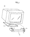
- Fig. 2 is a view showing a video monitor in which stereo speakers are attached to the lower face (for example, see JP-A-9-37372 (pages 2 and 3, Fig. 1)).
- left and right speakers 102L, 102R are placed so as to be attachable to and detachable from a television receiver main unit 101.
- Tweeter speaker units 104L, 105L or 104R, 105R are placed on each of two different faces 103a, 103b of a case.
- Woofer speaker units 106L, 106R which reproduce a relatively low sound region are placed on one of the two faces on which the tweeter speaker units are placed, i.e., the face 103a.
- engagement members 113, 113 protrude from upper faces of a case 112 which house speakers 111, 111, respectively.
- the engagement members 113, 113 are engaged with engagement holes formed in the lower face of the video monitor 110, whereby the case 112 can be detachably attached to the video monitor 110 with using a dead space between the monitor and a stand 114.
- the speakers may be attached respectively to the left and right sides of a display screen as shown in Fig. 1, or the speakers may be disposed below the display screen as shown in Fig. 2.
- These speakers are set so as to be attached predetermined positions of the upper or lower face, or the side faces of the case.
- the attachment positions cannot be changed to another face(s) (the upper, lower, and side faces).
- speakers 121 can be placed on the side faces or the lower face of the case 120 in a relatively easy manner as in an example shown in Figs. 3A and 3B in which relatively small speakers are placed, or in that shown in Figs. 4A and 4B in which speakers are placed on left and right sides, respectively, and made equal in height to the case.
- the product silhouette including the speakers 121 is distorted, and the design property is lost, and thewhole size of the product is increased.
- the unity of the product, the thinness, and the ratio of the screen size to the product size are reduced, and the degree of freedom of the installation environment is lowered, whereby the commercial value is largely reduced.
- It is an object of the invention is that, unlike the related art, while enabling attachment of speakers to be changed to different faces (upper, lower, and side faces) of a case, the loss of the design property and the increase of the production size can be prevented from occurring, whereby the above-mentioned reduction of the commercial value is blocked from being caused.
- a flat display apparatus including: a substantially rectangular case in which a flat type display unit for displaying an image is housed; and a stereo speaker device including a left channel speaker section and a right channel speaker section which are substantially same dimensions, wherein the left channel speaker section and the right channel speaker section are attachable to and detachable from at least one of an upper face of the case and a lower face of the case in a long-side direction of the left and right channel speaker sections with being laterally arranged in one row, the left channel speaker section and the right channel speaker section are respectively attachable to and detachable from a left side of the case and a right side face of the case, and a length defined in the long-side direction of at least one of the left channel speaker section and the right channel speaker section is equal to or smaller than one half of a length in a long-side direction of the case.
- Fig. 5A is a front view of a flat display apparatus of the embodiment showing the case where a stereo speaker device is attached to the lower face of a case
- Fig. 5B is a front view showing the case where the stereo speaker device is attached to the left and right side faces of the case, respectively.
- the flat display apparatus 10 has: a substantially rectangular case 22 in which a flat type display unit 21 for displaying an image is housed; and a stereo speaker device 30 consisting of a left channel speaker section 31L and a right channel speaker section 31R which have substantially same dimensions.
- the display unit 21 for example, a PDP (Plasma Display Panel), an organic EL display panel, or a liquid crystal display panel may be used.
- the display unit 21 is surrounded by a front face frame 20.
- the back face of the display unit is covered by a rear cover 23 (see Fig. 6).
- the display unit is housed in the case 22 which is rectangular as seen from the front side.
- Each of the left channel speaker section 31L and the right channel speaker section 31R is configured by adequately disposing, for example, a high-range speaker unit and a low-range speaker unit, or a full-range speaker unit, etc.
- the dimensions of the case 22 are indicated in the following manner.
- the length (width) in the long-side direction (lateral direction) is L0
- the length (height) in the short-side direction (vertical direction) is H.
- the left channel speaker section 31L and the right channel speaker section 31R have a length in the long-side direction of L1.
- the length L1 is equal to or smaller than one half of the width L0 of the case 22.
- Fig. 5A shows the case where L1 is one half of L0.
- the stereo speaker device 30 does not laterally protrude from the case 22 as shown in Fig. 5A.
- FIG. 5B shows the case where the left channel speaker section 31L and the right channel speaker section 31R are attached to the left and right side faces 22L, 22R of the case 22, respectively.
- a screen for wide vision or hi-vision is employed in the flat display apparatus 10.
- Such a screen has an aspect ratio of 16:9.
- the aspect ratio of the case 22 is about 2:1.
- the height H of the case 22 is slightly larger than one half of the width L0, and spaces 32 are formed between the upper and lower faces of the left channel speaker section 31L and the right channel speaker section 31R, and those of the case 22.
- the spaces are not so large that the unity of the product is impaired.
- the stereo speaker device is attachable to and detachable from at least one of the upper and lower faces 22U, 22D of the case, and also the side faces 22L, 22R of the case 22.
- the left channel speaker section 31L and the right channel speaker section 31R can be attached to the side faces 22L, 22R of the case 22, respectively, or alternatively to one of the upper and lower faces 22U, 22D of the case 22 with being laterally arranged in one row.
- the depth in the direction toward the back face is set to be as short as possible, so that the device does not protrude from the rear cover 23 behind the apparatus, or the length in the short-side direction is set to be as short as possible. According to the configuration, the reduction of the thickness and size of the flat display apparatus 10 can be further enhanced.
- Fig. 6A is a rear view showing a state where the stereo speaker device 30 is attached to the side faces 22L, 22R of the case 22, Fig. 6B is a side view, and Fig. 6C is a plan view.
- Fig. 7A is a plan view of an attachment piece which is used in attaching, Fig. 7B is a front view, and Fig. 7C is a side view.
- the left channel speaker section 31L and the right channel speaker section 31R are detachably attached by screws to the left and right side faces 22L, 22R of the case 22 of the flat display apparatus 10, via attachment pieces 40 which serve as attachment members, respectively.
- the rear cover 23 is attached to the back face of the flat display apparatus 10.
- each of the attachment pieces 40 has: a case attachment portion 41 which is to be attached to the case 22; and a speaker attachment portion 42 which is to be attached to corresponding one of the left channel speaker section 31L and the right channel speaker section 31R.
- Through holes 44 for attachment screws are opened in the case attachment portion 41 and the speaker attachment portion 42.
- the left channel speaker section 31L and the right channel speaker section 31R are detachably attached to the case 22 by fastening screws passed through the through holes 44 into screw holes formed in the case 22.
- An arm portion 43 for adjusting the level difference between the case attachment portion 41 and the speaker attachment portion 42 is disposed between the attachment portions 41, 42.
- the surfaces of the left channel speaker section 31L and the right channel speaker section 31R can be made close to the position (in the anteroposterior direction) of the surface of the display unit 21, or flush with the surface.
- Fig. 8A is a rear view showing a state where the speaker sections 31L, 31R are juxtaposedly attached to the lower face 22D of the case 22 and on the same plane
- Fig. 8B is side view
- Fig. 8C is a bottom view.
- Fig. 9A is a plan view showing an attachment piece which is to be used in a middle attaching portion
- Fig. 9B is a front view
- Fig. 9C is a side view
- Fig. 10A is a plan view showing an attachment piece which is to be used in left and right end attaching portions
- Fig. 10B is a front view
- Fig. 10C is a side view.
- the left channel speaker section 31L and the right channel speaker section 31R are detachably attached by screws to the lower face 22D of the case 22 of the flat display apparatus 10, via attachment pieces 50A, 50B.
- the figures show the case where the length L1 in the long-side direction of the left channel speaker section 31L and the right channel speaker section 31R is one half of the length L2 in the long-side direction of the case 22.
- the attachment piece 50A is formed into a substantially T-like shape, and has: a lateral portion 51 of the T-like shape which is to be attached to the case 22; and a vertical portion 52 of the T-like shape which continuously joins together side faces on the center side of the left channel speaker section 31L and the right channel speaker section 31R.
- the attachment piece further has horizontal portions 53 which perpendicular protrude from the lateral portion 51, and which are to be attached to the upper faces of the left channel speaker section 31L and the right channel speaker section 31R, respectively.
- a plurality of through holes 51a for a screw are opened in the lateral portion 51. Screws are passed through the through holes 51a, and then fastened into screw holes formed in the case 22, respectively.
- Two vertical rows of through holes 52a are disposed in the vertical portion 52. Screws passed through the through holes 52a of the rows are fastened into screw holes formed in end portions on the center side of the rear faces of the left channel speaker section 31L and the right channel speaker section 31R.
- Through holes 53a are opened in the horizontal portions 53, respectively. Screws passed through the through holes 53a are fastened into screw holes formed in end portions on the center side of the upper faces of the left channel speaker section 31L and the right channel speaker section 31R.
- middle portions of the left channel speaker section 31L and the right channel speaker section 31R are detachably attached to the lower face 22D of the case 22.
- each of the attachment pieces 50B is formed into a crank-like shape, and has: a case attachment portion 54 which is to be attached to the case 22; and a speaker attachment portion 55 which is to be attached to an outer end portion of corresponding one of the left channel speaker section 31L and the right channel speaker section 31R.
- An arm portion 56 is disposed between the case attachment portion 54 and the speaker attachment portion 55.
- the arm portion absorbs the step difference between the back face of the case 22 and the back face of corresponding one of the left channel speaker section 31L and the right channel speaker section 31R.
- the surfaces of the left channel speaker section 31L and the right channel speaker section 31R can be made substantially flush with the surface of the display unit 21.
- Through holes 54a for a screw are opened in the case attachment portion 54. Screws are passed through the through holes 54a, and then fastened into screw holes formed in the case 22.
- Through holes 55a are opened in the speaker attachment portion 55. Screws passed through the through holes 55a are fastened into screw holes formed in the upper face of corresponding one of the left channel speaker section 31L and the right channel speaker section 31R.
- outer end portions of the left channel speaker section 31L and the right channel speaker section 31R are detachably attached to the lower face 22D of the case 22.
- the left channel speaker section 31L and the right channel speaker section 31R can be detachably attached to the left and right side faces 22L, 22R of the case 22, respectively with using the attachment pieces 40, or alternatively to the lower face 22D of the case 22 with using the attachment pieces 50A, 50B.
- the speaker sections can be attached to either of the side faces 22L, 22R or the lower face 22D, so that the user can freely select the attachment position in accordance with the installation space and the design.
- the degree of freedom in the speaker layout can be enhanced without impairing the product value.
- the flat display apparatus 10 of the invention is not restricted to the embodiment described above, and may be adequately subjected to modification, improvement, etc.
- the stereo speaker device 30 is attached to the side faces 22L, 22R of the case 22, or to the lower face 22D.
- the stereo speaker device may be attached to the upper face 22U of the case 22.
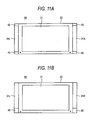
- spacers 45 may be placed above and below (Fig. 11A) or below (Fig. 11B, or, of course, above) the left channel speaker section 31L and the right channel speaker section 31R.
- the heights of the left channel speaker section 31L and the right channel speaker section 31R can be made coincident with the height of the case 22. Consequently, the silhouette of the whole product can be simplified, so that the appearance can be further improved.
- the spacers 45 may be provided with other functions, for example, a function of housing speaker cords, and a function of a holder for an accessory such as a remote controller.
- the flat display apparatus 10 of the embodiment has: a substantially rectangular case 22 in which the flat type display unit 21 for displaying an image is housed; and the stereo speaker device consisting of the left channel speaker section 31L and the right channel speaker section 31R which have substantially same dimensions.
- the left channel speaker section 31L and the right channel speaker section 31R are configured to enable the side faces in the long-side direction to be attached to and detached from the upper face 22U or the lower face 22D of the case 22 with being laterally arranged in one row, and also to be respectively attached to and detached from the left and right side faces 22L, 22R of the case 22.
- the length in the long-side direction of the left channel speaker section 31L or the right channel speaker section 31R is equal to or smaller than one half of the length in the long-side direction of the case 22.
- the configuration while enabling changing attachment of the stereo speaker device 30 to different faces (the upper, lower, and side faces) of the case 22, the loss of the design property and the increase of the production size can be prevented from occurring. Furthermore, it is possible to solve the problem in that, in contrast to the features of the flat display apparatus 10, or the reduced thickness and the large screen size, the unity of the product, the thinness, and the ratio of the screen size to the product size are reduced, and the degree of freedom of the installation environment is lowered, whereby the commercial value is largely reduced.
Landscapes
- Engineering & Computer Science (AREA)
- Signal Processing (AREA)
- Physics & Mathematics (AREA)
- Acoustics & Sound (AREA)
- Multimedia (AREA)
- Details Of Audible-Bandwidth Transducers (AREA)
- Devices For Indicating Variable Information By Combining Individual Elements (AREA)
- Stereophonic Arrangements (AREA)
Applications Claiming Priority (2)
| Application Number | Priority Date | Filing Date | Title |
|---|---|---|---|
| JP2003194773A JP2005033395A (ja) | 2003-07-10 | 2003-07-10 | 平面型表示装置 |
| JP2003194773 | 2003-07-10 |
Publications (2)
| Publication Number | Publication Date |
|---|---|
| EP1496721A2 true EP1496721A2 (de) | 2005-01-12 |
| EP1496721A3 EP1496721A3 (de) | 2009-01-14 |
Family
ID=33448008
Family Applications (1)
| Application Number | Title | Priority Date | Filing Date |
|---|---|---|---|
| EP04016095A Withdrawn EP1496721A3 (de) | 2003-07-10 | 2004-07-08 | Flachbildschirmgerät |
Country Status (3)
| Country | Link |
|---|---|
| US (1) | US20050031144A1 (de) |
| EP (1) | EP1496721A3 (de) |
| JP (1) | JP2005033395A (de) |
Cited By (2)
| Publication number | Priority date | Publication date | Assignee | Title |
|---|---|---|---|---|
| WO2009017278A1 (en) | 2007-07-30 | 2009-02-05 | Lg Electronics Inc. | Display device and speaker system for the display device |
| US8180074B2 (en) | 2007-01-02 | 2012-05-15 | Lg Electronics Inc. | Display device and speaker system for the display device |
Families Citing this family (11)
| Publication number | Priority date | Publication date | Assignee | Title |
|---|---|---|---|---|
| US7471804B2 (en) * | 2003-09-03 | 2008-12-30 | Monster Cable Products, Inc. | Flat panel monitor frame with integral speakers |
| US20050047616A1 (en) * | 2003-09-03 | 2005-03-03 | Noel Lee | Flat panel monitor frame with integral speakers |
| US7808563B2 (en) * | 2004-03-15 | 2010-10-05 | Steve Sanchez | Flat panel TV screen frame system |
| JP4528672B2 (ja) * | 2005-06-09 | 2010-08-18 | 株式会社東芝 | 映像表示装置 |
| JP2007282132A (ja) * | 2006-04-11 | 2007-10-25 | Sharp Corp | スピーカボックス取付構造及び表示装置 |
| JP2007318301A (ja) | 2006-05-24 | 2007-12-06 | Funai Electric Co Ltd | 薄型テレビジョン |
| US8223999B2 (en) * | 2008-04-02 | 2012-07-17 | Manufacturing Resources International, Inc. | Speaker configuration |
| KR20100019642A (ko) * | 2008-08-11 | 2010-02-19 | 삼성전자주식회사 | 스피커장치 및 이를 구비하는 영상표시장치 |
| JP2013012869A (ja) * | 2011-06-29 | 2013-01-17 | Sony Corp | 表示装置 |
| JP2013045103A (ja) * | 2011-08-26 | 2013-03-04 | Samsung Electronics Co Ltd | ディスプレイ装置 |
| JP2014075797A (ja) * | 2013-10-23 | 2014-04-24 | Toshiba Corp | 電子機器 |
Family Cites Families (11)
| Publication number | Priority date | Publication date | Assignee | Title |
|---|---|---|---|---|
| US5190258A (en) * | 1992-05-26 | 1993-03-02 | Yu Chung C | Articulated support assembly |
| JP3303353B2 (ja) * | 1992-09-18 | 2002-07-22 | ソニー株式会社 | テレビジョン受像機用スピーカ |
| DE69431356T2 (de) * | 1993-06-23 | 2003-04-17 | Apple Computer, Inc. | Computermonitor mit integriertem stereolautsprecher-richtmikrofon, und verfahren zur herstellung |
| US5701347A (en) * | 1994-06-23 | 1997-12-23 | Compaq Computer Corporation | Audio system for a personal computer |
| JP3275047B2 (ja) * | 1995-05-17 | 2002-04-15 | 株式会社ナナオ | ビデオモニタのスピーカユニットと、それを装着するビデオモニタ |
| US5812369A (en) * | 1996-10-04 | 1998-09-22 | Jazz Hipster, Inc. | Sound accessory for laptop/notebook computers |
| US6040978A (en) * | 1997-11-26 | 2000-03-21 | Gateway 2000, Inc. | Portable computer having folding speakers |
| JP3581627B2 (ja) * | 1999-02-24 | 2004-10-27 | キヤノン株式会社 | 画像表示装置 |
| JP2001117671A (ja) * | 1999-10-15 | 2001-04-27 | Nec Yonezawa Ltd | ノート型パーソナルコンピュータ |
| US6794798B2 (en) * | 2001-03-30 | 2004-09-21 | Taiyo Yuden Co., Ltd. | Display device and electronic equipment employing piezoelectric speaker |
| US6600827B2 (en) * | 2001-10-03 | 2003-07-29 | Kuan-Yu Chou | Externally mounted speaker for notebook computer |
-
2003
- 2003-07-10 JP JP2003194773A patent/JP2005033395A/ja active Pending
-
2004
- 2004-07-07 US US10/884,915 patent/US20050031144A1/en not_active Abandoned
- 2004-07-08 EP EP04016095A patent/EP1496721A3/de not_active Withdrawn
Cited By (4)
| Publication number | Priority date | Publication date | Assignee | Title |
|---|---|---|---|---|
| US8180074B2 (en) | 2007-01-02 | 2012-05-15 | Lg Electronics Inc. | Display device and speaker system for the display device |
| KR101340704B1 (ko) * | 2007-01-02 | 2013-12-12 | 엘지전자 주식회사 | 디스플레이 기기 및 디스플레이 기기를 위한 스피커 시스템 |
| WO2009017278A1 (en) | 2007-07-30 | 2009-02-05 | Lg Electronics Inc. | Display device and speaker system for the display device |
| EP2183912A4 (de) * | 2007-07-30 | 2011-06-22 | Lg Electronics Inc | Anzeigeanordnung und lautsprechersystem für die anzeigeanordnung |
Also Published As
| Publication number | Publication date |
|---|---|
| EP1496721A3 (de) | 2009-01-14 |
| US20050031144A1 (en) | 2005-02-10 |
| JP2005033395A (ja) | 2005-02-03 |
Similar Documents
| Publication | Publication Date | Title |
|---|---|---|
| EP1496721A2 (de) | Flachbildschirmgerät | |
| US8059843B2 (en) | Display device with sound module | |
| EP1487233A1 (de) | Bildanzeigeeinrichtung | |
| US7471804B2 (en) | Flat panel monitor frame with integral speakers | |
| US8717751B2 (en) | Protective enclosure | |
| US20130051596A1 (en) | Display apparatus | |
| JPH06105257A (ja) | テレビジョン受像機用スピーカ | |
| KR101195929B1 (ko) | 멀티 채널 영상 시스템 | |
| US7649733B2 (en) | Image display device | |
| JP7577998B2 (ja) | 表示装置 | |
| US20130101152A1 (en) | Display with sound box | |
| US8270652B2 (en) | Integrated television mount and audio system | |
| US20210195304A1 (en) | Display mount interfaces | |
| JP4923657B2 (ja) | スピーカ装置およびこのスピーカ装置を用いたテレビジョン受像機 | |
| JP2006237826A (ja) | 平面表示機器用スピーカ装置及び平面表示装置 | |
| US20090169045A1 (en) | Display Device with Hidden Speaker Assemblies | |
| CN211580077U (zh) | 一种具有AIoT声效的电视机 | |
| JP5752312B1 (ja) | 表示装置及びテレビジョン受信機 | |
| EP1864548B1 (de) | Mehrfach-lautsprecher-einrichtung | |
| KR20130004657U (ko) | 플렉서블 디스플레이를 이용한 중심부가 오목한 형태의 텔레비전 | |
| JP2020061636A (ja) | 表示装置、スピーカ装置、及びテレビジョン受像機 | |
| KR101314236B1 (ko) | 디스플레이장치 | |
| CN216217382U (zh) | 条形音箱及显示设备 | |
| CN111327850A (zh) | 一种具有AIoT声效的电视机 | |
| CN222366389U (zh) | 一种扬声器组件及一体机 |
Legal Events
| Date | Code | Title | Description |
|---|---|---|---|
| PUAI | Public reference made under article 153(3) epc to a published international application that has entered the european phase |
Free format text: ORIGINAL CODE: 0009012 |
|
| AK | Designated contracting states |
Kind code of ref document: A2 Designated state(s): AT BE BG CH CY CZ DE DK EE ES FI FR GB GR HU IE IT LI LU MC NL PL PT RO SE SI SK TR |
|
| AX | Request for extension of the european patent |
Extension state: AL HR LT LV MK |
|
| PUAL | Search report despatched |
Free format text: ORIGINAL CODE: 0009013 |
|
| AK | Designated contracting states |
Kind code of ref document: A3 Designated state(s): AT BE BG CH CY CZ DE DK EE ES FI FR GB GR HU IE IT LI LU MC NL PL PT RO SE SI SK TR |
|
| AX | Request for extension of the european patent |
Extension state: AL HR LT LV MK |
|
| AKX | Designation fees paid | ||
| STAA | Information on the status of an ep patent application or granted ep patent |
Free format text: STATUS: THE APPLICATION IS DEEMED TO BE WITHDRAWN |
|
| 18D | Application deemed to be withdrawn |
Effective date: 20090715 |
|
| REG | Reference to a national code |
Ref country code: DE Ref legal event code: 8566 |