EP1497023B1 - Procede de reduction de composes organiques volatiles (cov) dans des gaz d'echappement par effet couronne a impulsions humides - Google Patents
Procede de reduction de composes organiques volatiles (cov) dans des gaz d'echappement par effet couronne a impulsions humides Download PDFInfo
- Publication number
- EP1497023B1 EP1497023B1 EP03745184A EP03745184A EP1497023B1 EP 1497023 B1 EP1497023 B1 EP 1497023B1 EP 03745184 A EP03745184 A EP 03745184A EP 03745184 A EP03745184 A EP 03745184A EP 1497023 B1 EP1497023 B1 EP 1497023B1
- Authority
- EP
- European Patent Office
- Prior art keywords
- voc
- water
- exhaust gas
- stream
- gas stream
- Prior art date
- Legal status (The legal status is an assumption and is not a legal conclusion. Google has not performed a legal analysis and makes no representation as to the accuracy of the status listed.)
- Expired - Lifetime
Links
- 238000000034 method Methods 0.000 title claims abstract description 64
- 239000007789 gas Substances 0.000 title description 75
- 239000012855 volatile organic compound Substances 0.000 claims abstract description 86
- XLYOFNOQVPJJNP-UHFFFAOYSA-N water Substances O XLYOFNOQVPJJNP-UHFFFAOYSA-N 0.000 claims abstract description 77
- 239000007921 spray Substances 0.000 claims abstract description 20
- 238000007254 oxidation reaction Methods 0.000 claims abstract description 13
- 230000003647 oxidation Effects 0.000 claims abstract description 12
- 230000006378 damage Effects 0.000 claims abstract description 9
- 230000008569 process Effects 0.000 claims description 15
- 238000004519 manufacturing process Methods 0.000 claims description 14
- 239000002351 wastewater Substances 0.000 claims description 12
- 229910052751 metal Inorganic materials 0.000 claims description 9
- 239000002184 metal Substances 0.000 claims description 8
- 239000004033 plastic Substances 0.000 claims description 8
- 229920003023 plastic Polymers 0.000 claims description 8
- 238000004140 cleaning Methods 0.000 claims description 7
- 238000007747 plating Methods 0.000 claims description 6
- 239000003973 paint Substances 0.000 claims description 4
- 238000005504 petroleum refining Methods 0.000 claims description 4
- OKKJLVBELUTLKV-UHFFFAOYSA-N Methanol Chemical compound OC OKKJLVBELUTLKV-UHFFFAOYSA-N 0.000 description 49
- CSCPPACGZOOCGX-UHFFFAOYSA-N Acetone Chemical compound CC(C)=O CSCPPACGZOOCGX-UHFFFAOYSA-N 0.000 description 23
- 210000002381 plasma Anatomy 0.000 description 17
- QMMFVYPAHWMCMS-UHFFFAOYSA-N Dimethyl sulfide Chemical compound CSC QMMFVYPAHWMCMS-UHFFFAOYSA-N 0.000 description 15
- MWUXSHHQAYIFBG-UHFFFAOYSA-N nitrogen oxide Inorganic materials O=[N] MWUXSHHQAYIFBG-UHFFFAOYSA-N 0.000 description 9
- 150000001875 compounds Chemical class 0.000 description 8
- 230000005684 electric field Effects 0.000 description 8
- 238000005516 engineering process Methods 0.000 description 8
- 239000000463 material Substances 0.000 description 8
- 230000008901 benefit Effects 0.000 description 7
- 239000012071 phase Substances 0.000 description 7
- GRWFGVWFFZKLTI-IUCAKERBSA-N (-)-α-pinene Chemical compound CC1=CC[C@@H]2C(C)(C)[C@H]1C2 GRWFGVWFFZKLTI-IUCAKERBSA-N 0.000 description 6
- RAHZWNYVWXNFOC-UHFFFAOYSA-N Sulphur dioxide Chemical compound O=S=O RAHZWNYVWXNFOC-UHFFFAOYSA-N 0.000 description 6
- 238000010521 absorption reaction Methods 0.000 description 6
- 238000011282 treatment Methods 0.000 description 6
- 239000000047 product Substances 0.000 description 5
- 239000000126 substance Substances 0.000 description 5
- 239000006227 byproduct Substances 0.000 description 4
- 238000006243 chemical reaction Methods 0.000 description 4
- 239000011521 glass Substances 0.000 description 4
- 239000007788 liquid Substances 0.000 description 4
- 239000000203 mixture Substances 0.000 description 4
- 238000012545 processing Methods 0.000 description 4
- 239000002912 waste gas Substances 0.000 description 4
- MVNCAPSFBDBCGF-UHFFFAOYSA-N alpha-pinene Natural products CC1=CCC23C1CC2C3(C)C MVNCAPSFBDBCGF-UHFFFAOYSA-N 0.000 description 3
- 230000015572 biosynthetic process Effects 0.000 description 3
- 238000011109 contamination Methods 0.000 description 3
- 238000009792 diffusion process Methods 0.000 description 3
- 238000005265 energy consumption Methods 0.000 description 3
- 239000007791 liquid phase Substances 0.000 description 3
- 239000002245 particle Substances 0.000 description 3
- GRWFGVWFFZKLTI-UHFFFAOYSA-N rac-alpha-Pinene Natural products CC1=CCC2C(C)(C)C1C2 GRWFGVWFFZKLTI-UHFFFAOYSA-N 0.000 description 3
- 230000001172 regenerating effect Effects 0.000 description 3
- 239000000243 solution Substances 0.000 description 3
- 239000010935 stainless steel Substances 0.000 description 3
- 229910001220 stainless steel Inorganic materials 0.000 description 3
- 239000002699 waste material Substances 0.000 description 3
- OKTJSMMVPCPJKN-UHFFFAOYSA-N Carbon Chemical compound [C] OKTJSMMVPCPJKN-UHFFFAOYSA-N 0.000 description 2
- 239000004215 Carbon black (E152) Substances 0.000 description 2
- QAOWNCQODCNURD-UHFFFAOYSA-N Sulfuric acid Chemical compound OS(O)(=O)=O QAOWNCQODCNURD-UHFFFAOYSA-N 0.000 description 2
- 239000004809 Teflon Substances 0.000 description 2
- 229920006362 Teflon® Polymers 0.000 description 2
- 239000003929 acidic solution Substances 0.000 description 2
- 229910045601 alloy Inorganic materials 0.000 description 2
- 239000000956 alloy Substances 0.000 description 2
- 230000015556 catabolic process Effects 0.000 description 2
- 238000013461 design Methods 0.000 description 2
- 238000011161 development Methods 0.000 description 2
- WQOXQRCZOLPYPM-UHFFFAOYSA-N dimethyl disulfide Chemical compound CSSC WQOXQRCZOLPYPM-UHFFFAOYSA-N 0.000 description 2
- 230000008030 elimination Effects 0.000 description 2
- 238000003379 elimination reaction Methods 0.000 description 2
- 239000003344 environmental pollutant Substances 0.000 description 2
- 238000002474 experimental method Methods 0.000 description 2
- 238000010438 heat treatment Methods 0.000 description 2
- 229930195733 hydrocarbon Natural products 0.000 description 2
- 150000002430 hydrocarbons Chemical class 0.000 description 2
- 229910001026 inconel Inorganic materials 0.000 description 2
- 238000002347 injection Methods 0.000 description 2
- 239000007924 injection Substances 0.000 description 2
- 230000003993 interaction Effects 0.000 description 2
- 238000012423 maintenance Methods 0.000 description 2
- 230000007246 mechanism Effects 0.000 description 2
- VNWKTOKETHGBQD-UHFFFAOYSA-N methane Chemical compound C VNWKTOKETHGBQD-UHFFFAOYSA-N 0.000 description 2
- 238000012986 modification Methods 0.000 description 2
- 230000004048 modification Effects 0.000 description 2
- 231100000719 pollutant Toxicity 0.000 description 2
- 238000000746 purification Methods 0.000 description 2
- 230000000630 rising effect Effects 0.000 description 2
- 239000000523 sample Substances 0.000 description 2
- 235000007586 terpenes Nutrition 0.000 description 2
- 230000010718 Oxidation Activity Effects 0.000 description 1
- CBENFWSGALASAD-UHFFFAOYSA-N Ozone Chemical compound [O-][O+]=O CBENFWSGALASAD-UHFFFAOYSA-N 0.000 description 1
- XUIMIQQOPSSXEZ-UHFFFAOYSA-N Silicon Chemical compound [Si] XUIMIQQOPSSXEZ-UHFFFAOYSA-N 0.000 description 1
- NINIDFKCEFEMDL-UHFFFAOYSA-N Sulfur Chemical compound [S] NINIDFKCEFEMDL-UHFFFAOYSA-N 0.000 description 1
- 239000002250 absorbent Substances 0.000 description 1
- 230000002745 absorbent Effects 0.000 description 1
- 239000011358 absorbing material Substances 0.000 description 1
- 230000002378 acidificating effect Effects 0.000 description 1
- 239000003463 adsorbent Substances 0.000 description 1
- 238000004458 analytical method Methods 0.000 description 1
- 238000013459 approach Methods 0.000 description 1
- 239000008346 aqueous phase Substances 0.000 description 1
- 239000001273 butane Substances 0.000 description 1
- 239000003575 carbonaceous material Substances 0.000 description 1
- 239000000919 ceramic Substances 0.000 description 1
- 238000001311 chemical methods and process Methods 0.000 description 1
- 238000002485 combustion reaction Methods 0.000 description 1
- 230000008878 coupling Effects 0.000 description 1
- 238000010168 coupling process Methods 0.000 description 1
- 238000005859 coupling reaction Methods 0.000 description 1
- 238000005336 cracking Methods 0.000 description 1
- 125000004122 cyclic group Chemical group 0.000 description 1
- 230000006866 deterioration Effects 0.000 description 1
- 238000007865 diluting Methods 0.000 description 1
- 230000003467 diminishing effect Effects 0.000 description 1
- 238000010494 dissociation reaction Methods 0.000 description 1
- 230000005593 dissociations Effects 0.000 description 1
- 238000004090 dissolution Methods 0.000 description 1
- 230000000694 effects Effects 0.000 description 1
- 238000010891 electric arc Methods 0.000 description 1
- 238000010894 electron beam technology Methods 0.000 description 1
- 230000005284 excitation Effects 0.000 description 1
- 238000005562 fading Methods 0.000 description 1
- 238000004817 gas chromatography Methods 0.000 description 1
- 230000006872 improvement Effects 0.000 description 1
- 239000002440 industrial waste Substances 0.000 description 1
- 239000010842 industrial wastewater Substances 0.000 description 1
- 239000004615 ingredient Substances 0.000 description 1
- 150000002500 ions Chemical class 0.000 description 1
- 238000005259 measurement Methods 0.000 description 1
- 239000003595 mist Substances 0.000 description 1
- IJDNQMDRQITEOD-UHFFFAOYSA-N n-butane Chemical compound CCCC IJDNQMDRQITEOD-UHFFFAOYSA-N 0.000 description 1
- OFBQJSOFQDEBGM-UHFFFAOYSA-N n-pentane Natural products CCCCC OFBQJSOFQDEBGM-UHFFFAOYSA-N 0.000 description 1
- 239000003345 natural gas Substances 0.000 description 1
- 150000002894 organic compounds Chemical class 0.000 description 1
- 239000007800 oxidant agent Substances 0.000 description 1
- 229920001296 polysiloxane Polymers 0.000 description 1
- 230000009257 reactivity Effects 0.000 description 1
- 230000009467 reduction Effects 0.000 description 1
- 238000005201 scrubbing Methods 0.000 description 1
- 238000000926 separation method Methods 0.000 description 1
- 229910052710 silicon Inorganic materials 0.000 description 1
- 239000010703 silicon Substances 0.000 description 1
- 239000002594 sorbent Substances 0.000 description 1
- 238000005507 spraying Methods 0.000 description 1
- 229910052717 sulfur Inorganic materials 0.000 description 1
- 239000011593 sulfur Substances 0.000 description 1
- 230000002459 sustained effect Effects 0.000 description 1
- 150000003505 terpenes Chemical class 0.000 description 1
- 238000012546 transfer Methods 0.000 description 1
- 230000009466 transformation Effects 0.000 description 1
- 230000035899 viability Effects 0.000 description 1
- 238000004065 wastewater treatment Methods 0.000 description 1
Images


Classifications
-
- B—PERFORMING OPERATIONS; TRANSPORTING
- B01—PHYSICAL OR CHEMICAL PROCESSES OR APPARATUS IN GENERAL
- B01J—CHEMICAL OR PHYSICAL PROCESSES, e.g. CATALYSIS OR COLLOID CHEMISTRY; THEIR RELEVANT APPARATUS
- B01J19/00—Chemical, physical or physico-chemical processes in general; Their relevant apparatus
- B01J19/08—Processes employing the direct application of electric or wave energy, or particle radiation; Apparatus therefor
- B01J19/087—Processes employing the direct application of electric or wave energy, or particle radiation; Apparatus therefor employing electric or magnetic energy
- B01J19/088—Processes employing the direct application of electric or wave energy, or particle radiation; Apparatus therefor employing electric or magnetic energy giving rise to electric discharges
-
- B—PERFORMING OPERATIONS; TRANSPORTING
- B01—PHYSICAL OR CHEMICAL PROCESSES OR APPARATUS IN GENERAL
- B01D—SEPARATION
- B01D53/00—Separation of gases or vapours; Recovering vapours of volatile solvents from gases; Chemical or biological purification of waste gases, e.g. engine exhaust gases, smoke, fumes, flue gases, aerosols
- B01D53/32—Separation of gases or vapours; Recovering vapours of volatile solvents from gases; Chemical or biological purification of waste gases, e.g. engine exhaust gases, smoke, fumes, flue gases, aerosols by electrical effects other than those provided for in group B01D61/00
-
- B—PERFORMING OPERATIONS; TRANSPORTING
- B01—PHYSICAL OR CHEMICAL PROCESSES OR APPARATUS IN GENERAL
- B01D—SEPARATION
- B01D53/00—Separation of gases or vapours; Recovering vapours of volatile solvents from gases; Chemical or biological purification of waste gases, e.g. engine exhaust gases, smoke, fumes, flue gases, aerosols
- B01D53/34—Chemical or biological purification of waste gases
- B01D53/38—Removing components of undefined structure
- B01D53/44—Organic components
-
- B—PERFORMING OPERATIONS; TRANSPORTING
- B01—PHYSICAL OR CHEMICAL PROCESSES OR APPARATUS IN GENERAL
- B01D—SEPARATION
- B01D2257/00—Components to be removed
- B01D2257/70—Organic compounds not provided for in groups B01D2257/00 - B01D2257/602
- B01D2257/708—Volatile organic compounds V.O.C.'s
-
- B—PERFORMING OPERATIONS; TRANSPORTING
- B01—PHYSICAL OR CHEMICAL PROCESSES OR APPARATUS IN GENERAL
- B01D—SEPARATION
- B01D2259/00—Type of treatment
- B01D2259/80—Employing electric, magnetic, electromagnetic or wave energy, or particle radiation
- B01D2259/818—Employing electrical discharges or the generation of a plasma
-
- B—PERFORMING OPERATIONS; TRANSPORTING
- B01—PHYSICAL OR CHEMICAL PROCESSES OR APPARATUS IN GENERAL
- B01J—CHEMICAL OR PHYSICAL PROCESSES, e.g. CATALYSIS OR COLLOID CHEMISTRY; THEIR RELEVANT APPARATUS
- B01J2219/00—Chemical, physical or physico-chemical processes in general; Their relevant apparatus
- B01J2219/08—Processes employing the direct application of electric or wave energy, or particle radiation; Apparatus therefor
- B01J2219/0803—Processes employing the direct application of electric or wave energy, or particle radiation; Apparatus therefor employing electric or magnetic energy
- B01J2219/0805—Processes employing the direct application of electric or wave energy, or particle radiation; Apparatus therefor employing electric or magnetic energy giving rise to electric discharges
- B01J2219/0807—Processes employing the direct application of electric or wave energy, or particle radiation; Apparatus therefor employing electric or magnetic energy giving rise to electric discharges involving electrodes
- B01J2219/0824—Details relating to the shape of the electrodes
- B01J2219/0826—Details relating to the shape of the electrodes essentially linear
- B01J2219/0828—Wires
-
- B—PERFORMING OPERATIONS; TRANSPORTING
- B01—PHYSICAL OR CHEMICAL PROCESSES OR APPARATUS IN GENERAL
- B01J—CHEMICAL OR PHYSICAL PROCESSES, e.g. CATALYSIS OR COLLOID CHEMISTRY; THEIR RELEVANT APPARATUS
- B01J2219/00—Chemical, physical or physico-chemical processes in general; Their relevant apparatus
- B01J2219/08—Processes employing the direct application of electric or wave energy, or particle radiation; Apparatus therefor
- B01J2219/0803—Processes employing the direct application of electric or wave energy, or particle radiation; Apparatus therefor employing electric or magnetic energy
- B01J2219/0805—Processes employing the direct application of electric or wave energy, or particle radiation; Apparatus therefor employing electric or magnetic energy giving rise to electric discharges
- B01J2219/0807—Processes employing the direct application of electric or wave energy, or particle radiation; Apparatus therefor employing electric or magnetic energy giving rise to electric discharges involving electrodes
- B01J2219/0824—Details relating to the shape of the electrodes
- B01J2219/0826—Details relating to the shape of the electrodes essentially linear
- B01J2219/083—Details relating to the shape of the electrodes essentially linear cylindrical
-
- B—PERFORMING OPERATIONS; TRANSPORTING
- B01—PHYSICAL OR CHEMICAL PROCESSES OR APPARATUS IN GENERAL
- B01J—CHEMICAL OR PHYSICAL PROCESSES, e.g. CATALYSIS OR COLLOID CHEMISTRY; THEIR RELEVANT APPARATUS
- B01J2219/00—Chemical, physical or physico-chemical processes in general; Their relevant apparatus
- B01J2219/08—Processes employing the direct application of electric or wave energy, or particle radiation; Apparatus therefor
- B01J2219/0803—Processes employing the direct application of electric or wave energy, or particle radiation; Apparatus therefor employing electric or magnetic energy
- B01J2219/0805—Processes employing the direct application of electric or wave energy, or particle radiation; Apparatus therefor employing electric or magnetic energy giving rise to electric discharges
- B01J2219/0845—Details relating to the type of discharge
- B01J2219/0849—Corona pulse discharge
-
- B—PERFORMING OPERATIONS; TRANSPORTING
- B01—PHYSICAL OR CHEMICAL PROCESSES OR APPARATUS IN GENERAL
- B01J—CHEMICAL OR PHYSICAL PROCESSES, e.g. CATALYSIS OR COLLOID CHEMISTRY; THEIR RELEVANT APPARATUS
- B01J2219/00—Chemical, physical or physico-chemical processes in general; Their relevant apparatus
- B01J2219/08—Processes employing the direct application of electric or wave energy, or particle radiation; Apparatus therefor
- B01J2219/0873—Materials to be treated
- B01J2219/0875—Gas
Definitions
- the invention was made in the frame of a DOE sponsored project, Project Identification No. DE-FC07-00ID13868. The government has certain rights in the invention pursuant to that support.
- Non-thermal plasmas are an emerging technology for abating diluting volatile organic compounds (VOC) emissions. These plasmas can be produced by a variety of electrical discharges or electron beams.
- the basic feature of plasma technologies is that they produce plasma in which the majority of the electric energy (more than 99%) goes into production of energetic electrons, instead of heating the entire gas stream. These energetic electrons produce excited species, free radicals and ions) as well as additional electrons through the electron impact dissociation, excitation and ionization of the background molecules. These excited species, in turn, oxidize, reduce, or decompose the pollutant molecules.
- This mechanism of VOC removal is in contrast to the mechanism involved in thermal processes (such as plasma torches or furnaces, regenerative thermal oxidation (RTO) and several chemical techniques) that require heating the entire gas stream in order to destroy pollutants.
- thermal processes such as plasma torches or furnaces, regenerative thermal oxidation (RTO) and several chemical techniques
- RTO regenerative thermal oxidation
- the low-temperature plasma technology is highly selective and has relatively low maintenance requirements. Its high selectivity results in relatively low energy costs for emissions control while low maintenance keeps annual operating expenses low.
- these plasma discharges are very uniform and homogeneous (except gliding arcs), which results in high process productivity.
- RTO is more effective at high concentrations of VOC.
- Plasma is normally used at lower concentrations of VOC and in the cases where combustion is not effective, such as removal of nitrogen oxides (NO x ) or sulfur-containing compounds. Scrubbing of exhaust gases with water might be required for both techniques, but some plasma reactors can be designed as a single unit with a scrubber to reduce the equipment cost.
- the gliding arc is a high-pressure gas discharge with high electron temperature and density and has been proposed for chemical gas processing [ Lesueur et al., J. de Physique 51: C557-C564, 1990 ].
- the arc starts in a narrow gap between two or more diverging electrodes in a gas flow when the electric field in this gap reaches approximately 3 kV/mm in air [ Raizer, Gas Discharge Physics, Berlin, Springer-Verlag, 1997 ]. Then the arc current increases very rapidly, and the voltage on the arc drops. If the gas flow is strong enough, it forces the arc to move along the diverging electrodes and to elongate.
- the growing arc demands more power to sustain itself. At the moment when its resistance becomes equal to the total external resistance, the discharge consumes one-half of the power delivered by the source. This is the maximum power that can be transferred to the arc from the constant-voltage power supply. Next, the length continues increasing, but the supplied power is insufficient to balance the energy lost in heat transfer to the surrounding gas. The arc cools down and finally extinguishes. The next cycle starts immediately after the voltage reaches the breakdown value, usually just after the fading of the previous arc. (If the voltage is high enough, and the gap is very narrow, a new arc starts even before extinguishing of the old one [ Pellerin et al., J. Physics D-Applied Physics, 33(19): 2407-2419, 2000 ]. A typical repetition rate of the arc is in the range from 10 Hz to 100 Hz and changes with the gas flow rate: the higher is the flow rate, the higher is the frequency.
- the low-current (from 0.1 to 1 A) gliding arcs are believed to operate in non-equilibrium regimes ( T ⁇ T e ), and have low gas temperatures.
- the arc voltage could be as high as several kilovolts.
- Typical vibrational and translational temperatures of the gas in a low-temperature gliding arc were measured to be respectively about 2000 - 3000K and 800 - 2100 K [ Czernihowski et al., Acta Physica Polonica A, 89: 595 -603, 1996 ].
- Similar features are also intrinsic for microwave discharges; showing that low-current gliding arcs could be definitely useful for plasma chemistry.
- Methanol 100 to 1000 ppm was used as a substance to demonstrate viability of the gliding arc technology.
- water was sprayed along the flow direction. It was found that at 20 SLM of air and independently of VOC concentration, all methanol was removed from the stream at power consumption of 0.2 kW ⁇ hr/m 3 . No organic byproducts were detected by gas chromatography in the exhaust stream. The results were interpreted as encouraging, showing the possibility for further reduction of power consumption. Unfortunately, NO x was detected in the exhaust at level of 3000 ppm, much exceeding all reasonable limits. It could be expected, however, that for more non-equilibrium arcs with lower currents or higher flow rates of air, the temperature of the arc channel will be lower, and reasonable levels of NO x will be achieved.
- Corona is a self-sustained electrical gas discharge that occurs only when the electric field is sharply non-uniform.
- the width of the applied pulse must be minimized in order to avoid formation of spark discharge or thermalization of the streamers.
- the pulse rise time must be on the order of few nanoseconds and the duration of the pulse on the order of 100 ns.
- the electron energy in fact, depends on both the intensity of the electric field (i.e. on the voltage) and the mean free path.
- the mean electric field is very high (since the peak voltage is high), allowing the electrons to gain enough energy for the discharge to take place; however, since the duration of each pulse is much smaller than the interval between pulses, the mean required power is low (e.g., it is in the order of few Watts for the setups used for these experiments) even though the actual power of each single pulse is very high (about 1 MW).
- the negative polarity is predetermined by the existing equipment.
- DC corona is a uniform discharge. In contrary, the pulsed corona is highly non-uniform. All the discharge power is localized in streamers. To describe the physics of the discharge, one must consider a phenomenon of a streamer as a whole. Electromagnetic model of physics in streamers must be coupled with chemistry of excited species, and with internal particles (electrons, photons) transport. This coupling is very difficult because of enormous amount of computational work. Simplified models were developed, but they are still not adequate for the purposes of trustworthy chemistry prediction. Many parameters are known with great degree of uncertainty, such as electron cross-sections.
- VOC volatile organic compounds
- PPCP and SPCP are completely dry processes having a simple construction, and their overall cost (both initial and running) is one of the lowest among the processes for control of gaseous pollutants. They can be combined with a wet ESP, a bag-filter with absorbent powder coat, a catalyst bed, or an active charcoal bed for the final removal of the reaction products.
- VOC contamination levels that are several times higher (e.g., about 100 to about 6000 ppm), so usual plasma methods for VOC removal are not applicable.
- the invention described hereinafter provides one method by which the latter, more highly loaded exhaust gas streams can be abated of VOC.
- the present invention contemplates a method for treating exhaust gas streams that contain one or more volatile organic compounds (VOC) to abate those VOCs.
- VOC volatile organic compounds
- a method for abatement of volatile organic compounds (VOC) in an exhaust as stream which comprises passing an exhaust gas stream through a pulsed corona discharge chamber in the presence of a spray of water droplets or a flowing film of water to form one or more oxidation products that dissolve in the water spray droplets or flowing film to thereby provide an effluent water stream and an effluent gas stream, wherein (a) the pulsed corona discharges at a rate of about 0.01 to about 2 kHz, (b) the ratio of the water spray or flow rate to the exhaust gas flow is about 0.2 to about 2 milliliters/minute at one standard liter per minute of exhaust gas flow, and (c) an expenditure of not more than 50 eV per molecule of VOC is utilized, the method providing a destruction and removal efficiency of about 90 percent or more, thereby abating the VOC.
- VOC volatile organic compounds
- a contemplated method for abatement of VOCs in an exhaust gas stream comprises passing an exhaust gas stream containing about 60 to about 6000 ppm VOC, and more usually about 200 to about 3000 ppm, through a pulsed corona discharge chamber in the presence of a spray of water droplets or a flowing film of water to form one or more oxidation products that dissolve in the water spray droplets or film and provide an effluent water stream and an effluent gas stream.
- a contemplated pulsed corona discharges at a rate of about 0.01 to about 2 kHz.
- the ratio of the water spray rate to the exhaust gas flow is about 0.2 to about 2 milliliters/minute at one standard liter per minute of exhaust gas flow, and an expenditure of not more than 50 eV per molecule of VOC is utilized.
- This method provides a destruction and removal efficiency of about 90 percent or more, thereby abating the VOC.
- the method can operate at substantially any temperature with the understanding that lower temperatures typically provide slower reaction rates.
- the method is utilized in part of a waste treatment system in which the relatively small amount of water that contains the dissolved oxidation products produced in this method is admixed with the relatively larger volume of industrial waste water produced by papermaking, metal cleaning or plating process or plastics manufacturing process.
- the method is utilized after the gas phase is contacted with water as a mist of particles about 0.1 to about 1 millimeter in diameter or liquid water to dissolve and thereby capture water-soluble VOC such as methanol and acetone.
- the effluent gas from such a pretreatment is then passed into the wet pulsed corona discharge process discussed above with the liquid phase being further subjected to bioremediation or another type of purification treatment.
- the gas phase produced from the above process is passed over a gaseous sorbent (absorbent and/or adsorbent) system such as activated charcoal and vented to the air or passed into an air stream of an incinerator or the like to eliminate vestigial VOC that may have escaped elimination in a previous step.
- a gaseous sorbent absorbent and/or adsorbent
- the present invention has several benefits and advantages.
- One benefit is that high levels of VOC elimination efficiency can be obtained at relatively low start-up and running costs.
- An advantage of the invention is that the products produced by the pulsed corona discharge reaction on the VOC are typically more soluble than are many of the VOC so that those materials can be more readily dissolved in the water flow that is used.
- Another benefit of the invention is that the method and apparatus utilized are adaptable to being utilized with other air and water purification systems or methods.
- This method is applicable to substantially any existing waste gas stream that emanates from an industrial site such as a metal cleaning and plating, paint manufacturing, plastics manufacturing, petroleum refining and dye-making site that also includes a wastewater treatment facility for treating a waste water stream from a source other than the pulsed corona discharge.
- the present invention contemplates a method for treating exhaust gas streams that contain one or more volatile organic compounds (VOC) to abate those VOCs.
- VOC volatile organic compounds
- Illustrative exhaust gas streams include, without limitation, those streams produced by papermaking, metal cleaning and plating, paint manufacturing, plastics manufacture, petroleum refining, dye-making and the like industries.
- a contemplated method is particularly useful in abating VOC produced in papermaking processes such as brownstock and oriented strandboard production (whose VOC are similar to those of papermaking), and particularly from the vents streams and dryer exhausts used in those processes.
- a contemplated method for abatement of VOCs in an exhaust gas stream comprises passing an exhaust gas stream containing about 60 to about 6000 ppm VOC through a pulsed corona discharge chamber in the presence of a spray of water droplets or a flowing film of water to form one or more oxidation products that dissolve in the water spray droplets or film and provide an effluent water stream and an effluent gas stream.
- a contemplated pulsed corona discharges at a rate of about 0.01 to about 2 kHz, and more preferably about 0.1 to about 1 kHz.
- the ratio of the water spray or flow rate to the exhaust gas flow is about 0.2 to about 2 milliliters/minute at one standard liter per minute of exhaust gas flow, and an expenditure of not more than 50 eV per molecule of VOC is utilized. This method provides a destruction and removal efficiency of about 90 percent or more, to about 99 percent or more, thereby abating the VOC.
- the method can operate at substantially any temperature with the understanding that lower temperatures typically provide slower reaction rates, as is usually the case for chemical reactions. More typical temperatures of the exhaust gas stream are about 103° F (about 40°C) to about 150° F (about 65° C). Such temperatures are determined prior to entry into the pulsed corona discharge apparatus.
- VOC levels are about 200 to about 4200 ppm. More preferably still, those VOC levels are about 300 to about 3000 ppm.
- the water spray or flow rate and the exhaust gas flow volume can differ from one apparatus and gas stream to another.
- the ratio of water spray or flow rate to the exhaust gas flow is relatively constant at about 0.2 to about 2 milliliters/minute at one standard liter per minute (SLM) of exhaust gas flow.
- SLM standard liter per minute
- the water spray or flow rate can be on the order of gallons, liters or kiloliters per minute, with an accompanying increase in gas stream flow so that the ratio of the two corresponds to that noted above.
- HVLC high volume low concentration
- the wet corona setup permits for a water film to flow on the internal walls of the reactor.
- a water spray can be used instead of water film.
- the flow of water is scalable based on the size of the apparatus used, the VOC present in the exhaust gas, the volume of gas flow and other known or readily determined parameters that are associated with Henry's law and the equations discussed hereinafter.
- a wet pulse corona discharge system 10 is schematically represented in Fig. 1 . That figure shows a reactor 12 having internal walls 12a over which a water film is permitted to flow. It will be understood by persons having skill in the art that in a larger scalable geometry a water spray can be used instead of a flow, without departing from the novel scope of the present invention.
- a corona discharge wire 14 is provided within reactor 12.
- the reactor 12 and wire 14 create a wire-into-cylinder coaxial electrode system 16.
- the inner, high voltage electrode 14 is, in a preferred embodiment, a 0.5 mm diameter Inconel ® wire.
- the Inconel ® alloy is selected for its superior heat and oxidation resistance. It will, however, be understood that other alloys or single metallic element wires, can be used without departing from the novel scope of the present invention.
- the reactor vessel 12 creates an external electrode 18, made up, in a preferred embodiment of the present invention, of a 60 cm long cylindrical glass tube 20 with an internal diameter 22, in a preferred embodiment the diameter is 22.2 mm, surrounded by a sheet of perforated metal 23.
- the internal wall 20a of the glass tube 20 is covered by a layer of absorbing material 24, which forms a uniformly distributed water film in the reactor 12.
- the tube 20 is held, in a preferred embodiment, at the top by a Teflon ® holder (not shown) and at the bottom by a stainless steel holder (not shown); stainless steel is preferred for the bottom of the reactor to prevent deterioration of the holder itself due to the byproducts expected in the liquid phase, such as sulfuric acid.
- a Teflon ® holder not shown
- stainless steel is preferred for the bottom of the reactor to prevent deterioration of the holder itself due to the byproducts expected in the liquid phase, such as sulfuric acid.
- the reactor 12 is sealed, in a preferred, by means of silicon O-rings (not shown).Although silicone O-rings are used in a preferred embodiment, it will be understood that O-rings of other materials, including rubber and plastic, can be used without departing from the novel scope of the present invention.
- the top holder (not shown) comprises the connections of the lines, which are schematically shown in Fig. 1 , for the incoming water 30 and the outgoing (effluent) gas 32.
- water is introduced into the reactor 12 through sixteen, equally spaced holes with a diameter of 1 / 32 " (about 0.8 mm), to provide a uniform injection around the circular tube. It will be understood that any number of equally spaced holes, of various suitable diameters (either uniformly of the same diameter or of different diameters with suitable results) can be used to provide a uniform injection of water, without departing from the novel scope of the present invention.
- the top holder also contains the connection for the internal, high voltage electrode 14 and for the high voltage probe (shown schematically in Fig. 1 ).
- the bottom holder (not shown) includes threaded holes for the gas inlet 40 and for the water outlet (effluent) 42 (shown schematically in Fig. 1 ).
- the wire 14 can be fixed to the holder (not shown) through a Teflon ® insert (not shown), which completely contains the lower portion of the wire.
- Teflon ® insert (not shown), which completely contains the lower portion of the wire.
- the type of insert described is a preferred embodiment and is not meant to limit the scope of the present invention.
- Power is supplied, in a preferred embodiment, to the plasma source by a thyratron-based power supply 50, with 100 k ⁇ internal resistance and no-load voltage values from 0 to 20 kV. It will be understood that similar power supplies, having desirable power producing capabilities, can be utilized without departing from the novel scope of the present invention.
- pulses of about 100 ns duration and 10 ns rise time are applied and are transmitted to the central wire electrode 14 by means of a 50 ⁇ high-voltage, coaxial cable 52.
- the power of the plasma source is varied from 1 to 20 W by controlling the high voltage pulse amplitude and the pulse frequency, which could range from 0.01 to 2 kHz. Voltage is measured using a high voltage probe (not shown) such as model P6015A 1000X by Tektronik Inc., current measurements are performed, in a preferred embodiment, using a standard current monitor such as current monitor #411 by Pearson Inc.
- an electrode 14 is placed within glass tube 20, water is input into the system in such a manner that a film of water forms on the internal walls 12a of the reactor 12, simultaneously an exhaust gas stream containing VOC is introduced and the electrode is charged.
- the result includes the oxidation of VOC, their dissolution in the flowing water effluent and the release of gas phase byproducts in the gas effluent.
- c a is the concentration of a species in the aqueous phase and p g is the partial pressure of that species in the gas phase.
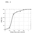
- Methanol removal by absorption into water was studied in the wet corona reactor. An initial concentration equal to 200 ppm of methanol was considered. Methanol is the most soluble among the organic compounds of interest, as Table II shows.
- the value of the critical water flow rate for absorbing methanol was calculated from the model to be Q w-crit about 0.2 ml/min, in good agreement with the experimental results shown in Fig. 2 .
- the DRE is almost complete (about 99.9%), suggesting that an optimal configuration in terms of the geometry of the reactor and of the ratio between gas and liquid flow rate has been obtained for the removal of methanol.
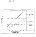
- Acetone removal by absorption into water was studied for flow rate of the water film varying from zero to about 2 ml/min.
- the initial concentration of acetone in the gas stream was 200 ppm.
- Q w-crit about 1.3 ml/min, higher than for methanol, given the lower solubility in water; experimental results, presented in Fig. 3 , show good agreement with the theoretical calculations.
- a high removal efficiency about 99% can be reached using a fairly low water flow rate (about 2 ml/min).
- substantially all soluble VOC components like methanol or acetone, are removed from the stream by water, and the only one radical OH produced by the pulsed corona discharge is used for treatment of one molecule of insoluble VOC, like dimethylsulfide.
- Molecules of insoluble VOCs are non-polar; this is a reason of their very low solubility. After the interaction of OH radical with the molecule of insoluble VOC, this molecule transforms into a new molecule or radical, which is polar and more soluble. Then this more soluble substance is removed by the water stream of the scrubber. As a result not more than 50 eV per molecule of VOC is spent, and this system is applicable for the waste stream with higher level of contamination (about 200 ppm of insoluble VOC and any reasonable level of soluble VOC).
- the gas flow rate was 1 SLM, and water flow rate was 1.5 ml/min.
- the radicals being dissolved in the water produce acidic solutions (pH ⁇ 7). Additionally, ozone molecules from the corona discharge also dissolve in the pulsed corona water flow to make it more acidic. As a result, the corona device is built from the materials that are stable to acidic solution: stainless steel, plastics, glass, carbon materials, and the like.
- the particular plant has the wastewater that is of such quality that it can be used in spray systems and does not produce considerable amount of VOCs during spraying, this wastewater can be used in the corona discharge apparatus.
- RTO regenerative thermal oxidizers
Landscapes
- Chemical & Material Sciences (AREA)
- Engineering & Computer Science (AREA)
- Chemical Kinetics & Catalysis (AREA)
- Oil, Petroleum & Natural Gas (AREA)
- Health & Medical Sciences (AREA)
- Analytical Chemistry (AREA)
- General Chemical & Material Sciences (AREA)
- Environmental & Geological Engineering (AREA)
- Biomedical Technology (AREA)
- General Health & Medical Sciences (AREA)
- Toxicology (AREA)
- Organic Chemistry (AREA)
- Treating Waste Gases (AREA)
- Physical Or Chemical Processes And Apparatus (AREA)
Claims (14)
- Procédé de réduction de composés organiques volatiles (COV) dans un courant de gaz d'échappement, qui comprend :le passage d'un courant de gaz d'échappement à travers une chambre à effet couronne pulsé en présence de gouttelettes d'eau pulvérisées ou d'un film d'eau en écoulement pour former un ou plusieurs produits d'oxydation qui se dissolvent dans les gouttelettes d'eau pulvérisées ou le film d'eau en écoulement pour ainsi fournir un courant d'effluent aqueux et un courant d'effluent gazeux,dans lequel(a) la fréquence dudit effet couronne pulsé est d'environ 0,01 à environ 2 kHz,(b) le rapport entre le débit de pulvérisation d'eau ou d'écoulement et le flux du gaz d'échappement est d'environ 0,2 à environ 2 millilitres/minute pour un litre standard par minute de flux de gaz d'échappement, et(c) une dépense d'au plus 50 eV par molécule de COV est utilisée, ledit procédé fournissant une efficacité de destruction et d'élimination d'environ 90 pour cent ou plus, pour ainsi réduire lesdits COV.
- procédé selon la revendication 1, dans lequel la fréquence dudit effet couronne puisé est d'environ 0,1 à environ 1 kHz.
- Procédé selon la revendication 1, dans lequel ledit courant de gaz d'échappement contient environ 60 à environ 6000 ppm de COV.
- Procédé selon la revendication 1, dans lequel ledit courant de gaz d'échappement est celui produit par un procédé choisi dans le groupe constitué par la fabrication du papier, le nettoyage ou le placage des métaux, la fabrication des peintures, la fabrication des plastiques, le raffinage du pétrole et la fabrication des colorants.
- Procédé selon la revendication 1, utilisé pour réduire les COV provenant d'un courant de gaz d'échappement issu d'un procédé choisi dans le groupe constitué par la fabrication du papier, le nettoyage ou le placage des métaux, la fabrication des peintures, la fabrication des plastiques, le raffinage du pétrole et la fabrication des colorants, et dans lequel le courant de gaz d'échappement contient environ 60 à environ 6000 ppm de COV.
- Procédé selon la revendication 5, dans lequel ledit procédé est mené à une température de courant d'échappement d'environ 40 °C à environ 65 °C.
- Procédé selon la revendication 5, dans lequel ledit courant d'échappement contient environ 200 à environ 4200 ppm de COV.
- Procédé selon la revendication 5, dans lequel ledit courant d'échappement est produit dans un procédé de fabrication de papier.
- Procédé selon la revendication 1, utilisé pour réduire les COV provenant d'un courant de gaz d'échappement à une température d'environ 40 °C à environ 65 °C produit dans un procédé de fabrication de papier, qui contient environ 200 à environ 4200 ppm de COV, ledit procédé fournissant une efficacité de destruction et d'élimination d'environ 90 pour cent ou plus, pour ainsi réduite lesdits COV.
- Procédé selon la revendication 9, dans lequel ledit courant d'échappement contient d'environ 300 à environ 3000 ppm de COV.
- Procédé selon la revendication 9, dans lequel ladite efficacité d'élimination est d'environ 99 pour cent ou plus.
- Procédé selon la revendication 9, dans lequel ledit procédé de fabrication du papier est la production de pâte brune ou de panneaux de grandes particules orientées.
- Procédé selon la revendication 9, comprenant l'étape supplémentaire de mélange du courant d'effluent aqueux contenant les COV oxydés avec un autre courant d'eau usée.
- Procédé selon la revendication 9, dans lequel l'eau de ladite eau pulvérisée provient des eaux usées dudit procédé de fabrication de papier.
Applications Claiming Priority (3)
| Application Number | Priority Date | Filing Date | Title |
|---|---|---|---|
| US36723102P | 2002-03-25 | 2002-03-25 | |
| US367231P | 2002-03-25 | ||
| PCT/US2003/009089 WO2003080234A1 (fr) | 2002-03-25 | 2003-03-24 | Procede de reduction de composes organiques volatiles (cov) dans des gaz d'echappement par effet couronne a impulsions humides |
Publications (3)
| Publication Number | Publication Date |
|---|---|
| EP1497023A1 EP1497023A1 (fr) | 2005-01-19 |
| EP1497023A4 EP1497023A4 (fr) | 2005-11-23 |
| EP1497023B1 true EP1497023B1 (fr) | 2009-09-16 |
Family
ID=28454842
Family Applications (1)
| Application Number | Title | Priority Date | Filing Date |
|---|---|---|---|
| EP03745184A Expired - Lifetime EP1497023B1 (fr) | 2002-03-25 | 2003-03-24 | Procede de reduction de composes organiques volatiles (cov) dans des gaz d'echappement par effet couronne a impulsions humides |
Country Status (7)
| Country | Link |
|---|---|
| US (1) | US20060039844A1 (fr) |
| EP (1) | EP1497023B1 (fr) |
| AT (1) | ATE442899T1 (fr) |
| AU (1) | AU2003256189A1 (fr) |
| DE (1) | DE60329285D1 (fr) |
| ES (1) | ES2333420T3 (fr) |
| WO (1) | WO2003080234A1 (fr) |
Families Citing this family (9)
| Publication number | Priority date | Publication date | Assignee | Title |
|---|---|---|---|---|
| JP4111229B2 (ja) * | 2006-05-19 | 2008-07-02 | ダイキン工業株式会社 | 放電装置及び空気浄化装置 |
| US8952612B1 (en) | 2006-09-15 | 2015-02-10 | Imaging Systems Technology, Inc. | Microdischarge display with fluorescent conversion material |
| US8142727B2 (en) * | 2008-12-09 | 2012-03-27 | Eisenmann Corporation | Valveless regenerative thermal oxidizer for treating closed loop dryer |
| NL2003259C2 (en) * | 2009-07-22 | 2011-01-25 | Univ Delft Tech | Method for the removal of a gaseous fluid and arrangement therefore. |
| KR101321113B1 (ko) | 2011-08-29 | 2013-10-23 | 한국기계연구원 | 유해성 가스 처리용 와이어-실린더형 플라즈마 반응기 |
| KR20190039445A (ko) * | 2016-09-02 | 2019-04-11 | 솜니오 글로벌 홀딩스, 엘엘씨 | 자유 라디칼 발생 장치 및 그 제조 방법 |
| CN109663431B (zh) * | 2019-01-18 | 2024-04-12 | 华南理工大学 | 一种具有脱硫除尘功能的VOCs综合治理系统 |
| CN112058194B (zh) * | 2019-12-23 | 2023-05-30 | 沈阳农业大学 | 液相脉冲放电等离子体处理反应装置及处理方法 |
| GB2593786B (en) | 2020-07-07 | 2023-01-25 | Daphne Tech Sa | Apparatus and method for electron irradiation scrubbing |
Family Cites Families (9)
| Publication number | Priority date | Publication date | Assignee | Title |
|---|---|---|---|---|
| US4181675A (en) * | 1978-09-19 | 1980-01-01 | Monsanto Company | Process for methanol production |
| US4695358A (en) * | 1985-11-08 | 1987-09-22 | Florida State University | Method of removing SO2, NOX and particles from gas mixtures using streamer corona |
| US5120771A (en) * | 1989-09-13 | 1992-06-09 | Hickory Springs Manufacturing Co. | Process for the production of polyurethane foam |
| US5637198A (en) * | 1990-07-19 | 1997-06-10 | Thermo Power Corporation | Volatile organic compound and chlorinated volatile organic compound reduction methods and high efficiency apparatus |
| US5549795A (en) * | 1994-08-25 | 1996-08-27 | Hughes Aircraft Company | Corona source for producing corona discharge and fluid waste treatment with corona discharge |
| US5695619A (en) * | 1995-05-25 | 1997-12-09 | Hughes Aircraft | Gaseous pollutant destruction method using self-resonant corona discharge |
| US5861123A (en) * | 1996-04-26 | 1999-01-19 | Ceco Filters, Inc. | Ultraviolet light irradiated ebullating mass transfer system |
| US7045099B2 (en) * | 2000-02-18 | 2006-05-16 | LK Luftqualität AG | Method for the treatment of air of at least one room by air ionization |
| US6905577B1 (en) * | 2000-07-24 | 2005-06-14 | Ozomax Inc. | Method for oxidation of volatile organic compounds contained in gaseous effluents and device thereof |
-
2003
- 2003-03-24 AT AT03745184T patent/ATE442899T1/de not_active IP Right Cessation
- 2003-03-24 ES ES03745184T patent/ES2333420T3/es not_active Expired - Lifetime
- 2003-03-24 US US10/531,129 patent/US20060039844A1/en not_active Abandoned
- 2003-03-24 EP EP03745184A patent/EP1497023B1/fr not_active Expired - Lifetime
- 2003-03-24 DE DE60329285T patent/DE60329285D1/de not_active Expired - Lifetime
- 2003-03-24 WO PCT/US2003/009089 patent/WO2003080234A1/fr not_active Ceased
- 2003-03-24 AU AU2003256189A patent/AU2003256189A1/en not_active Abandoned
Also Published As
| Publication number | Publication date |
|---|---|
| US20060039844A1 (en) | 2006-02-23 |
| DE60329285D1 (de) | 2009-10-29 |
| WO2003080234A1 (fr) | 2003-10-02 |
| EP1497023A4 (fr) | 2005-11-23 |
| AU2003256189A1 (en) | 2003-10-08 |
| ES2333420T3 (es) | 2010-02-22 |
| EP1497023A1 (fr) | 2005-01-19 |
| ATE442899T1 (de) | 2009-10-15 |
Similar Documents
| Publication | Publication Date | Title |
|---|---|---|
| Mok et al. | Decomposition of volatile organic compounds and nitric oxide by nonthermal plasma discharge processes | |
| US6524538B2 (en) | Method and apparatus for plasma treatment of gas | |
| Ighigeanu et al. | SO2 and NOx removal by electron beam and electrical discharge induced non-thermal plasmas | |
| Hu et al. | Transformations and destruction of nitrogen oxides—NO, NO2 and N2O—in a pulsed corona discharge reactor☆ | |
| US6139694A (en) | Method and apparatus utilizing ethanol in non-thermal plasma treatment of effluent gas | |
| CN101066791A (zh) | 三相交流滑动弧非平衡等离子体污水处理装置 | |
| Radoiu et al. | Emission control of SO2 and NOx by irradiation methods | |
| US6576573B2 (en) | Atmospheric pressure plasma enhanced abatement of semiconductor process effluent species | |
| US7521026B2 (en) | Field-enhanced electrodes for additive-injection non-thermal plasma (NTP) processor | |
| EP1497023B1 (fr) | Procede de reduction de composes organiques volatiles (cov) dans des gaz d'echappement par effet couronne a impulsions humides | |
| JP2002151295A (ja) | 放電発生装置 | |
| US7063819B2 (en) | Nonthermal plasma processor utilizing additive-gas injection and/or gas extraction | |
| Hu et al. | The destruction of N2O in a pulsed corona discharge reactor | |
| US5340450A (en) | Removal of organic materials from a gas | |
| Moon et al. | SO/sub 2/and CO gas removal and discharge characteristics of a nonthermal plasma reactor in a crossed DC magnetic field | |
| Mizuno | Recent progress and applications of non-thermal plasma | |
| Guan et al. | Degradation of toluene with negative DC corona plasma enhanced by microdischarge | |
| Brandenburg et al. | Plasma-based depollution of exhausts: principles, state of the art and future prospects | |
| Li et al. | Decomposition of toluene by using a streamer discharge reactor combined with catalysts | |
| Yan et al. | Evaluation of NOx removal by corona induced non-thermal plasmas | |
| Harada et al. | A novel design of electrodes system for gas treatment integrating ceramic filter and SPCP (surface corona discharge induced plasma chemical process) method | |
| Sobacchi et al. | Pulsed corona plasma technology for treating VOC emissions from pulp mills | |
| Litter | Thermal and non-thermal plasma for destruction of pollutants | |
| Tak et al. | Pulsed corona plasma pilot plant for VOC abatement in industrial streams as mobile and educational laboratory | |
| Fridman et al. | Pulsed corona plasma technology for treating VOC emissions from pulp mills |
Legal Events
| Date | Code | Title | Description |
|---|---|---|---|
| PUAI | Public reference made under article 153(3) epc to a published international application that has entered the european phase |
Free format text: ORIGINAL CODE: 0009012 |
|
| 17P | Request for examination filed |
Effective date: 20041022 |
|
| AK | Designated contracting states |
Kind code of ref document: A1 Designated state(s): AT BE BG CH CY CZ DE DK EE ES FI FR GB GR HU IE IT LI LU MC NL PT RO SE SI SK TR |
|
| AX | Request for extension of the european patent |
Extension state: AL LT LV MK |
|
| RIN1 | Information on inventor provided before grant (corrected) |
Inventor name: FRIDMAN, ALEXANDER Inventor name: KENNEDY, LAWRENCE Inventor name: GUTSOL, ALEXANDER Inventor name: SAVELIEV, ALEXEI |
|
| RIC1 | Information provided on ipc code assigned before grant |
Ipc: 7B 01D 53/72 B Ipc: 7B 01D 53/44 B Ipc: 7B 01J 19/08 A Ipc: 7B 01D 53/32 B Ipc: 7B 01D 53/48 B |
|
| A4 | Supplementary search report drawn up and despatched |
Effective date: 20051010 |
|
| GRAP | Despatch of communication of intention to grant a patent |
Free format text: ORIGINAL CODE: EPIDOSNIGR1 |
|
| GRAS | Grant fee paid |
Free format text: ORIGINAL CODE: EPIDOSNIGR3 |
|
| GRAA | (expected) grant |
Free format text: ORIGINAL CODE: 0009210 |
|
| AK | Designated contracting states |
Kind code of ref document: B1 Designated state(s): AT BE BG CH CY CZ DE DK EE ES FI FR GB GR HU IE IT LI LU MC NL PT RO SE SI SK TR |
|
| REG | Reference to a national code |
Ref country code: GB Ref legal event code: FG4D |
|
| REG | Reference to a national code |
Ref country code: CH Ref legal event code: EP |
|
| REG | Reference to a national code |
Ref country code: IE Ref legal event code: FG4D |
|
| REF | Corresponds to: |
Ref document number: 60329285 Country of ref document: DE Date of ref document: 20091029 Kind code of ref document: P |
|
| PG25 | Lapsed in a contracting state [announced via postgrant information from national office to epo] |
Ref country code: SE Free format text: LAPSE BECAUSE OF FAILURE TO SUBMIT A TRANSLATION OF THE DESCRIPTION OR TO PAY THE FEE WITHIN THE PRESCRIBED TIME-LIMIT Effective date: 20090916 Ref country code: FI Free format text: LAPSE BECAUSE OF FAILURE TO SUBMIT A TRANSLATION OF THE DESCRIPTION OR TO PAY THE FEE WITHIN THE PRESCRIBED TIME-LIMIT Effective date: 20090916 |
|
| REG | Reference to a national code |
Ref country code: ES Ref legal event code: FG2A Ref document number: 2333420 Country of ref document: ES Kind code of ref document: T3 |
|
| PG25 | Lapsed in a contracting state [announced via postgrant information from national office to epo] |
Ref country code: SI Free format text: LAPSE BECAUSE OF FAILURE TO SUBMIT A TRANSLATION OF THE DESCRIPTION OR TO PAY THE FEE WITHIN THE PRESCRIBED TIME-LIMIT Effective date: 20090916 Ref country code: NL Free format text: LAPSE BECAUSE OF FAILURE TO SUBMIT A TRANSLATION OF THE DESCRIPTION OR TO PAY THE FEE WITHIN THE PRESCRIBED TIME-LIMIT Effective date: 20090916 |
|
| NLV1 | Nl: lapsed or annulled due to failure to fulfill the requirements of art. 29p and 29m of the patents act | ||
| PG25 | Lapsed in a contracting state [announced via postgrant information from national office to epo] |
Ref country code: CY Free format text: LAPSE BECAUSE OF FAILURE TO SUBMIT A TRANSLATION OF THE DESCRIPTION OR TO PAY THE FEE WITHIN THE PRESCRIBED TIME-LIMIT Effective date: 20090916 |
|
| PG25 | Lapsed in a contracting state [announced via postgrant information from national office to epo] |
Ref country code: CZ Free format text: LAPSE BECAUSE OF FAILURE TO SUBMIT A TRANSLATION OF THE DESCRIPTION OR TO PAY THE FEE WITHIN THE PRESCRIBED TIME-LIMIT Effective date: 20090916 Ref country code: EE Free format text: LAPSE BECAUSE OF FAILURE TO SUBMIT A TRANSLATION OF THE DESCRIPTION OR TO PAY THE FEE WITHIN THE PRESCRIBED TIME-LIMIT Effective date: 20090916 Ref country code: RO Free format text: LAPSE BECAUSE OF FAILURE TO SUBMIT A TRANSLATION OF THE DESCRIPTION OR TO PAY THE FEE WITHIN THE PRESCRIBED TIME-LIMIT Effective date: 20090916 Ref country code: PT Free format text: LAPSE BECAUSE OF FAILURE TO SUBMIT A TRANSLATION OF THE DESCRIPTION OR TO PAY THE FEE WITHIN THE PRESCRIBED TIME-LIMIT Effective date: 20100118 |
|
| PGFP | Annual fee paid to national office [announced via postgrant information from national office to epo] |
Ref country code: ES Payment date: 20100326 Year of fee payment: 8 Ref country code: IE Payment date: 20100325 Year of fee payment: 8 |
|
| PG25 | Lapsed in a contracting state [announced via postgrant information from national office to epo] |
Ref country code: SK Free format text: LAPSE BECAUSE OF FAILURE TO SUBMIT A TRANSLATION OF THE DESCRIPTION OR TO PAY THE FEE WITHIN THE PRESCRIBED TIME-LIMIT Effective date: 20090916 |
|
| PGFP | Annual fee paid to national office [announced via postgrant information from national office to epo] |
Ref country code: FR Payment date: 20100406 Year of fee payment: 8 Ref country code: IT Payment date: 20100325 Year of fee payment: 8 |
|
| PG25 | Lapsed in a contracting state [announced via postgrant information from national office to epo] |
Ref country code: BE Free format text: LAPSE BECAUSE OF FAILURE TO SUBMIT A TRANSLATION OF THE DESCRIPTION OR TO PAY THE FEE WITHIN THE PRESCRIBED TIME-LIMIT Effective date: 20090916 Ref country code: AT Free format text: LAPSE BECAUSE OF FAILURE TO SUBMIT A TRANSLATION OF THE DESCRIPTION OR TO PAY THE FEE WITHIN THE PRESCRIBED TIME-LIMIT Effective date: 20090916 |
|
| PGFP | Annual fee paid to national office [announced via postgrant information from national office to epo] |
Ref country code: GB Payment date: 20100326 Year of fee payment: 8 |
|
| PLBE | No opposition filed within time limit |
Free format text: ORIGINAL CODE: 0009261 |
|
| STAA | Information on the status of an ep patent application or granted ep patent |
Free format text: STATUS: NO OPPOSITION FILED WITHIN TIME LIMIT |
|
| PG25 | Lapsed in a contracting state [announced via postgrant information from national office to epo] |
Ref country code: DK Free format text: LAPSE BECAUSE OF FAILURE TO SUBMIT A TRANSLATION OF THE DESCRIPTION OR TO PAY THE FEE WITHIN THE PRESCRIBED TIME-LIMIT Effective date: 20090916 |
|
| 26N | No opposition filed |
Effective date: 20100617 |
|
| PGFP | Annual fee paid to national office [announced via postgrant information from national office to epo] |
Ref country code: DE Payment date: 20100329 Year of fee payment: 8 |
|
| PG25 | Lapsed in a contracting state [announced via postgrant information from national office to epo] |
Ref country code: GR Free format text: LAPSE BECAUSE OF FAILURE TO SUBMIT A TRANSLATION OF THE DESCRIPTION OR TO PAY THE FEE WITHIN THE PRESCRIBED TIME-LIMIT Effective date: 20091217 Ref country code: MC Free format text: LAPSE BECAUSE OF NON-PAYMENT OF DUE FEES Effective date: 20100331 |
|
| REG | Reference to a national code |
Ref country code: CH Ref legal event code: PL |
|
| PG25 | Lapsed in a contracting state [announced via postgrant information from national office to epo] |
Ref country code: CH Free format text: LAPSE BECAUSE OF NON-PAYMENT OF DUE FEES Effective date: 20100331 Ref country code: LI Free format text: LAPSE BECAUSE OF NON-PAYMENT OF DUE FEES Effective date: 20100331 |
|
| GBPC | Gb: european patent ceased through non-payment of renewal fee |
Effective date: 20110324 |
|
| REG | Reference to a national code |
Ref country code: FR Ref legal event code: ST Effective date: 20111130 |
|
| REG | Reference to a national code |
Ref country code: IE Ref legal event code: MM4A |
|
| PG25 | Lapsed in a contracting state [announced via postgrant information from national office to epo] |
Ref country code: FR Free format text: LAPSE BECAUSE OF NON-PAYMENT OF DUE FEES Effective date: 20110331 Ref country code: IE Free format text: LAPSE BECAUSE OF NON-PAYMENT OF DUE FEES Effective date: 20110324 Ref country code: DE Free format text: LAPSE BECAUSE OF NON-PAYMENT OF DUE FEES Effective date: 20111001 |
|
| REG | Reference to a national code |
Ref country code: DE Ref legal event code: R119 Ref document number: 60329285 Country of ref document: DE Effective date: 20111001 |
|
| PG25 | Lapsed in a contracting state [announced via postgrant information from national office to epo] |
Ref country code: IT Free format text: LAPSE BECAUSE OF NON-PAYMENT OF DUE FEES Effective date: 20110324 Ref country code: GB Free format text: LAPSE BECAUSE OF NON-PAYMENT OF DUE FEES Effective date: 20110324 |
|
| REG | Reference to a national code |
Ref country code: ES Ref legal event code: FD2A Effective date: 20120509 |
|
| PG25 | Lapsed in a contracting state [announced via postgrant information from national office to epo] |
Ref country code: ES Free format text: LAPSE BECAUSE OF NON-PAYMENT OF DUE FEES Effective date: 20110325 |
|
| PG25 | Lapsed in a contracting state [announced via postgrant information from national office to epo] |
Ref country code: LU Free format text: LAPSE BECAUSE OF NON-PAYMENT OF DUE FEES Effective date: 20100324 Ref country code: BG Free format text: LAPSE BECAUSE OF FAILURE TO SUBMIT A TRANSLATION OF THE DESCRIPTION OR TO PAY THE FEE WITHIN THE PRESCRIBED TIME-LIMIT Effective date: 20090916 Ref country code: HU Free format text: LAPSE BECAUSE OF FAILURE TO SUBMIT A TRANSLATION OF THE DESCRIPTION OR TO PAY THE FEE WITHIN THE PRESCRIBED TIME-LIMIT Effective date: 20100317 |
|
| PG25 | Lapsed in a contracting state [announced via postgrant information from national office to epo] |
Ref country code: TR Free format text: LAPSE BECAUSE OF FAILURE TO SUBMIT A TRANSLATION OF THE DESCRIPTION OR TO PAY THE FEE WITHIN THE PRESCRIBED TIME-LIMIT Effective date: 20090916 |